Creating 3D Isometric view of various structural elements in AutoCAD
QUESTION NO -01
ANSWER :
AIM: CREATE A 3D ISOMETRIC VIEW OF THE BUILDING WITH THE PLAN AND ELEVATION GIVEN.
INTRODUCTION: IN THIS CHALLENGE WE HAVE TO DRAW THE 3D MODELLING OG GIVEN FURNITURE WITH THE USE OF AUTOCAD 3D
START THIS DRAWING FIRST OF ALL WE HAVE TO DO SOME SETTINGS ACCORDING TO THE DRAWING -
SOFTWARE SETTINGS
DRAWING-LINK:
https://web.autocad.com/acad/me/sid/shares/drawings/0587b620-831b-45fc-9b2e-9ed2a6329129/editor
SETTINGS - OPEN AUTOCAD
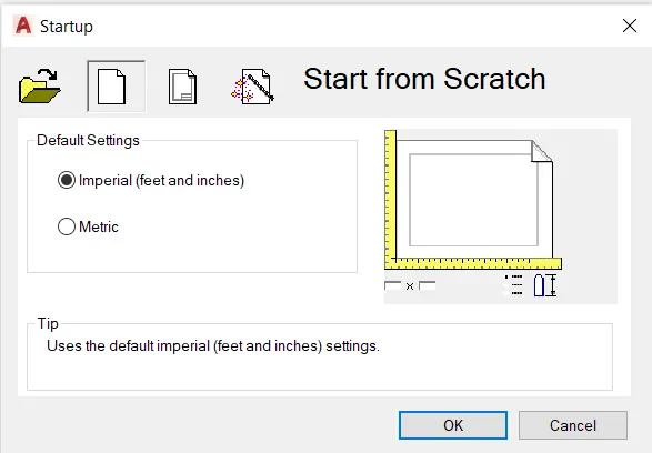
- SET DEFAULT SETTINGS - IMPERIAL UNIT (FEET AND INCHES )
- SELECT A TEMPLATE - ACCORDING TO DRAWINGS
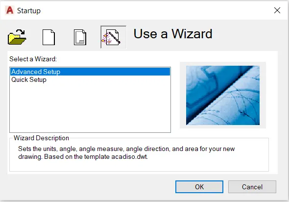
- SELECT A WIZARD - ADVANCED SETUP
- UNITS - DECIMAL
- ANGLE - DECIMAL DEGREES
- ANGLE MEASURE - ACCORDING TO THE PLAN
- ANGLE DIRECTION - COUNTER-CLOCKWISE
- AREA - ACCORDING TO THE PLAN
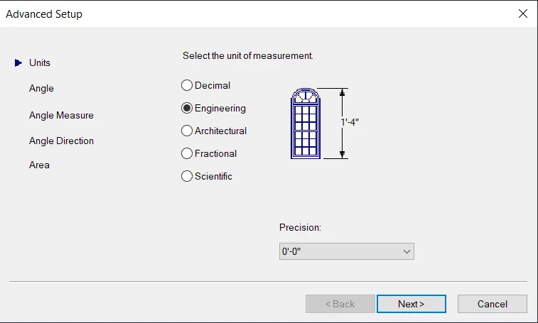
After this enter "D" for the dimension unit and set primary unit ARCHITECTURAL set precision 0'-0"
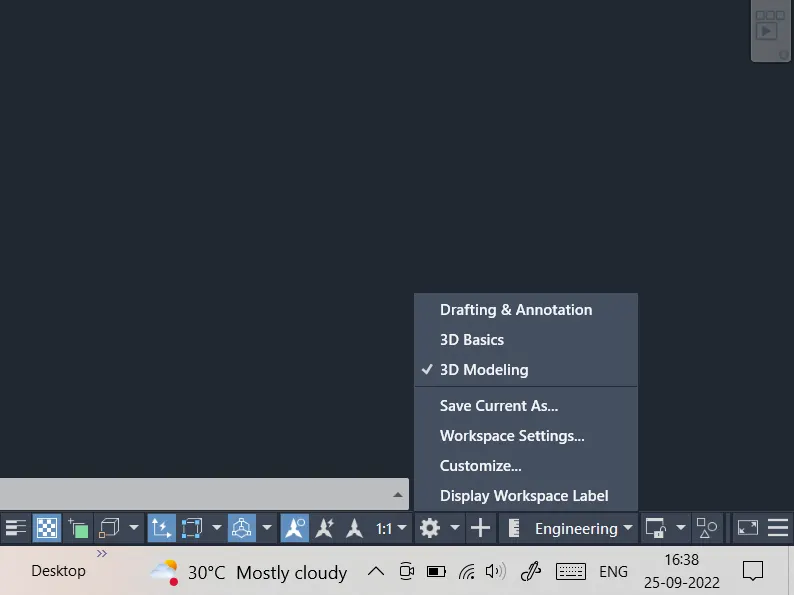
GO TO WORKSPACE SWITCHING - SELECT 3D MODELLING
MODES -
- GRID ON BY F7 'CONTROL+G'
- USE ORTHO MODE FOR STRAIGHT 90-DEGREE ACCORDING TO NEED(F8)
- ON POLAR TRACKING (F10) SET ANGLE (15,30,45)
- OBJET SNAP TRACKING (F11)
- OBJECT SNAP (F3)
- TRANPARANCY ON WHEN YOU NEED
OTHER DATA:
PROCEDURE: TO DRAW THE LAYOUT PLAN WE FOLLOW THE FOLLOWING STEPS: -
STEP-1
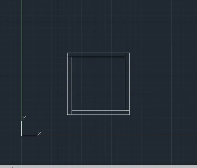
- To create the plan of the drawing. we take the line command
- take a line and draw the rectangle 10'x10'
- Tale offset of 9" and take offset both sides of the rectangle
STEP-2
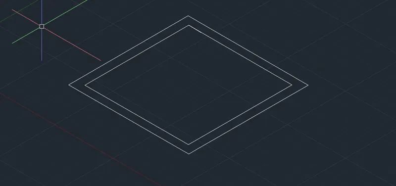
Go to isometric view
STEP-3
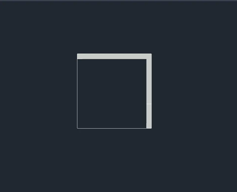
- After creating This go to the trim command and trim unwanted lines
- Now we get this.
- With the help of offset command take offset of 3'2"
- Noe again take offset 3' for window.
STEP-4
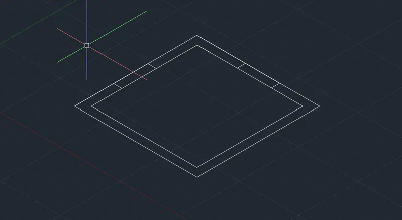
- Now we get this after offsetting and trim command.
- Now start to use the presspull command.
STEP-5
- With the help of presspull command pull the wall 4"
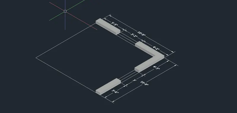
STEP-6
- Again take press pull command and take pull this 10' upward direction.
- pull all the given wall 10'
- Also pull the window portion 3' from the bottom 4" distance.
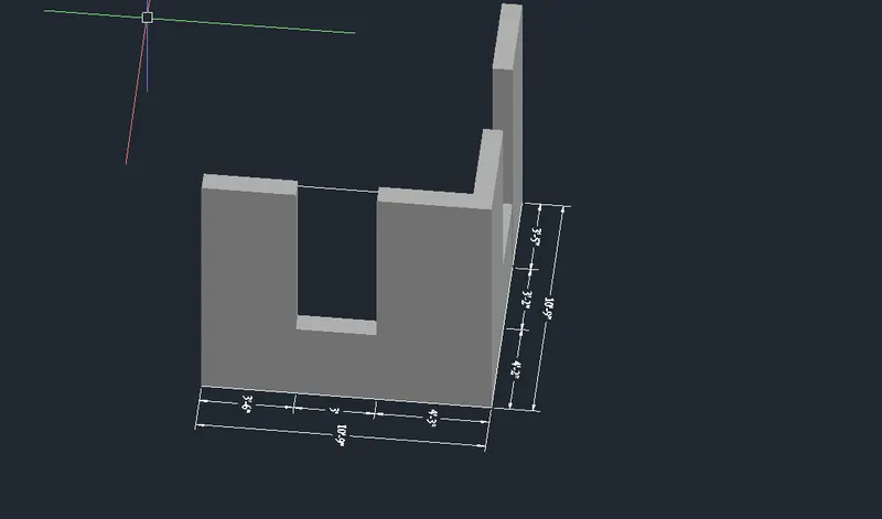
STEP-7
HIDDEN VIEW OF THE DRAWING:
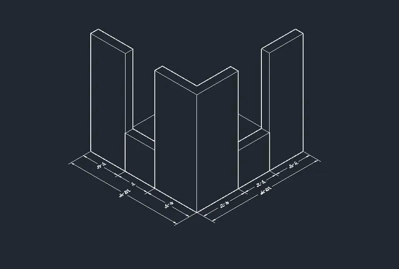
STEP-8
- Take copy command and copy the down wall of the window and paste it upper of the window.
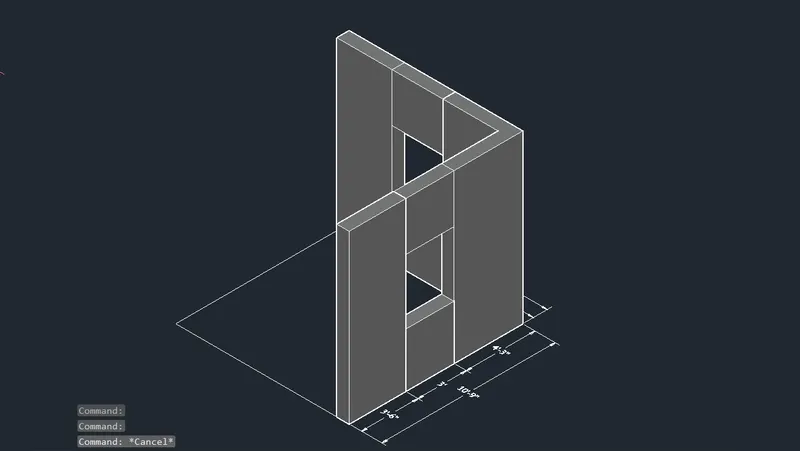
PLAN:
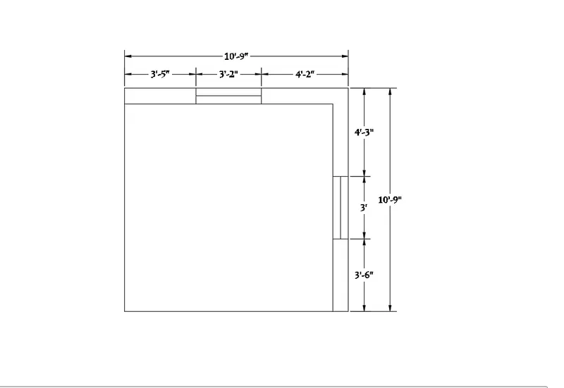
STEP-9
- use union command to conncet all portions .
ELEVATION B:
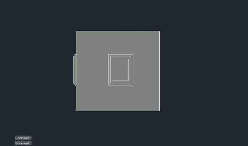
STEP-10
ELEVATION A:
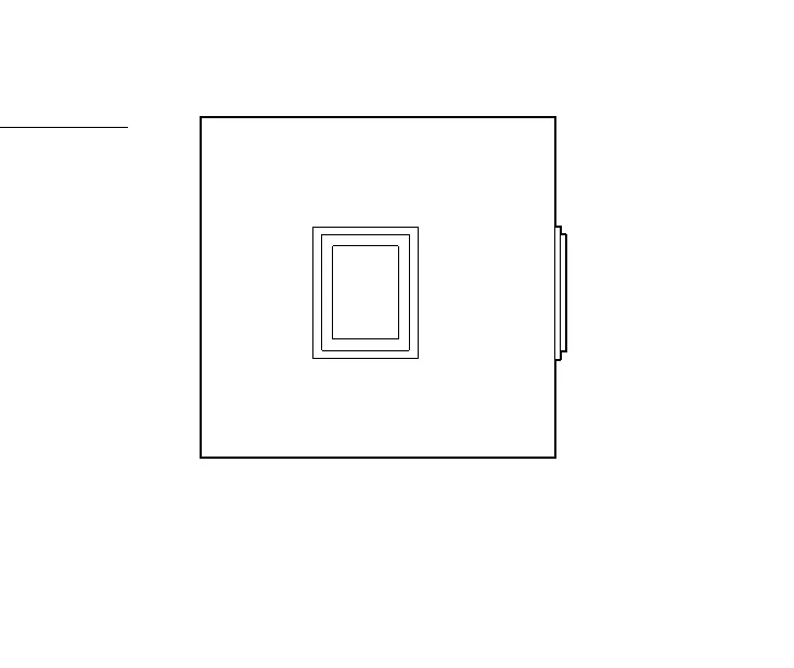
STEP-11
ISOWMETRIC VIEWS:
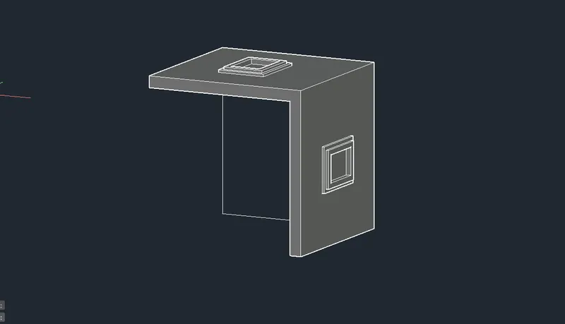
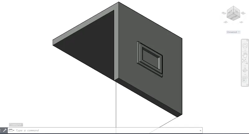
RESULT: THE GIVEN 3D DRAWING OF THE WALL WITH WINDOW ARE COMPLETED WITH THE GIVEN FIGURE.AFTER MAKING THE DRAWING FINAL DRAWING SCREENSHOTS ARE ATTACHED WITH THE RESULTANT DRAWING. THE LINK TO THE DRAWING OF AUTOCAD IS ALSO ATTACHED FOR REFERENCE.
AUTOCADE DRAWING FILE LINK:
https://web.autocad.com/acad/me/sid/shares/drawings/0587b620-831b-45fc-9b2e-9ed2a6329129/editor
https://web.autocad.com/acad/me/sid/shares/drawings/0587b620-831b-45fc-9b2e-9ed2a6329129/editor
RESULTANT DRAWING:
QUESTION NO -02
ANSWER :
AIM: CREATE THE 3D VIEW OF THE BUILDING FACADE AS GIVEN IN THE PLAN AND ELEVATION . ALSO SEE THE DETAILS OF THE WINDOW .
INTRODUCTION: IN THIS CHALLENGE WE HAVE TO DRAW THE 3D MODELLING OG GIVEN FURNITURE WITH THE USE OF AUTOCAD 3D
START THIS DRAWING FIRST OF ALL WE HAVE TO DO SOME SETTINGS ACCORDING TO THE DRAWING -
SOFTWARE SETTINGS
DRAWING-LINK:
https://web.autocad.com/acad/me/sid/shares/drawings/07658602-d8b8-4b18-a371-8a227b51ab9c/editor
SETTINGS - OPEN AUTOCAD
- SET DEFAULT SETTINGS - IMPERIAL UNIT (FEET AND INCHES )
- SELECT A TEMPLATE - ACCORDING TO DRAWINGS
- SELECT A WIZARD - ADVANCED SETUP
- UNITS - DECIMAL
- ANGLE - DECIMAL DEGREES
- ANGLE MEASURE - ACCORDING TO THE PLAN
- ANGLE DIRECTION - COUNTER-CLOCKWISE
- AREA - ACCORDING TO THE PLAN
After this enter "D" for the dimension unit and set primary unit ARCHITECTURAL set precision 0'-0"
GO TO WORKSPACE SWITCHING - SELECT 3D MODELLING
MODES -
- GRID ON BY F7 'CONTROL+G'
- USE ORTHO MODE FOR STRAIGHT 90-DEGREE ACCORDING TO NEED(F8)
- ON POLAR TRACKING (F10) SET ANGLE (15,30,45)
- OBJET SNAP TRACKING (F11)
- OBJECT SNAP (F3)
- TRANPARANCY ON WHEN YOU NEED
PROCEDURE: TO DRAW THE LAYOUT PLAN WE FOLLOW THE FOLLOWING STEPS: -
STEP-1
- To draw the building fadace take line command and this draw the plan
- take line command put 10'9" lin and bottom side 6'9" and take offset
- Take midpoint of bottom line and take offset 1.5' for window.
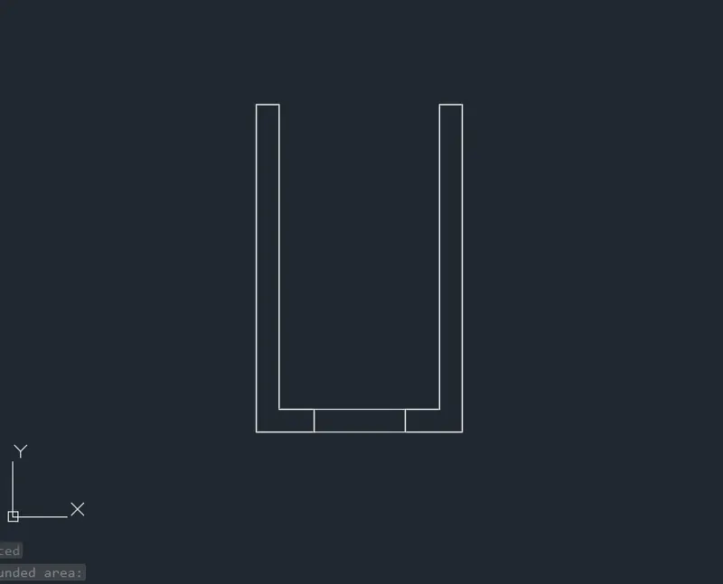
STEP-2
use prespull command and press this building with the segment.
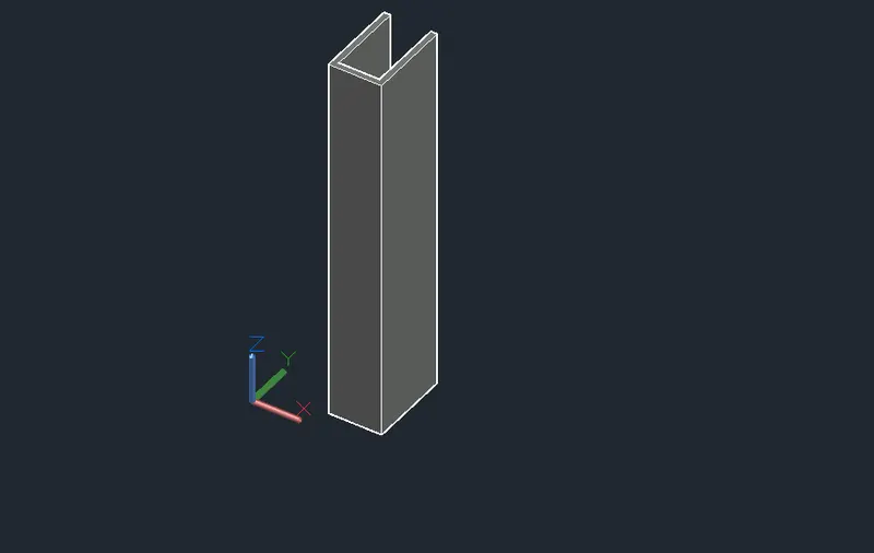
STEP-3
- Take line command and take diffrent segment for window.
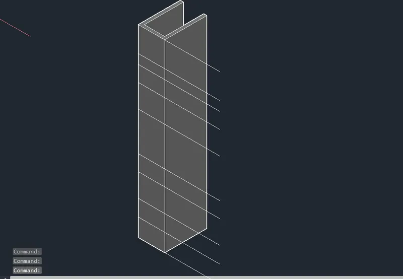
STEP-4
WINDOW CREATION:
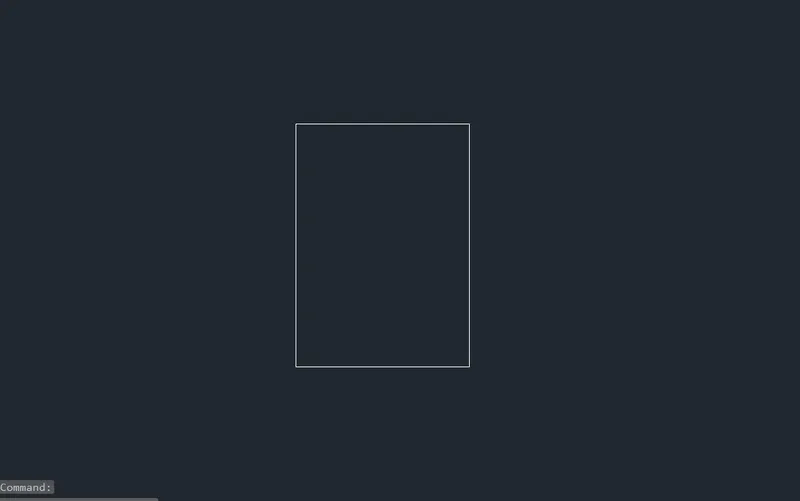
- Go to front view and take rec command draw the rectangle of 4'2" x 3'
- take offset of 2" internal side
- again take offset 3"
STEP-5
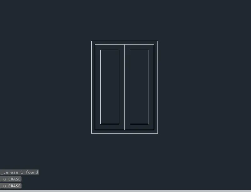
USE PRESSPULL
- take presspull command and pull the side of the window .
STEP-6
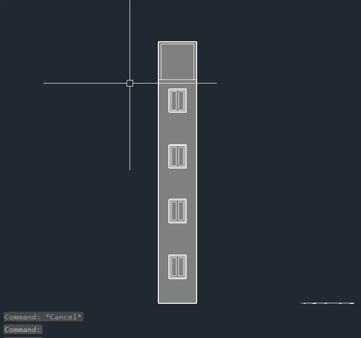
FRONT VIEW:
- Go to copy command and copy the window and put it with the help of diffrent segment of line.
STEP-7
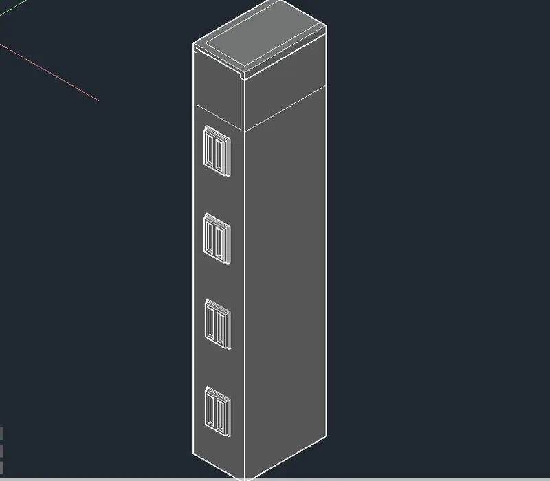
ISOMETRIC VIEW:
PLAN:
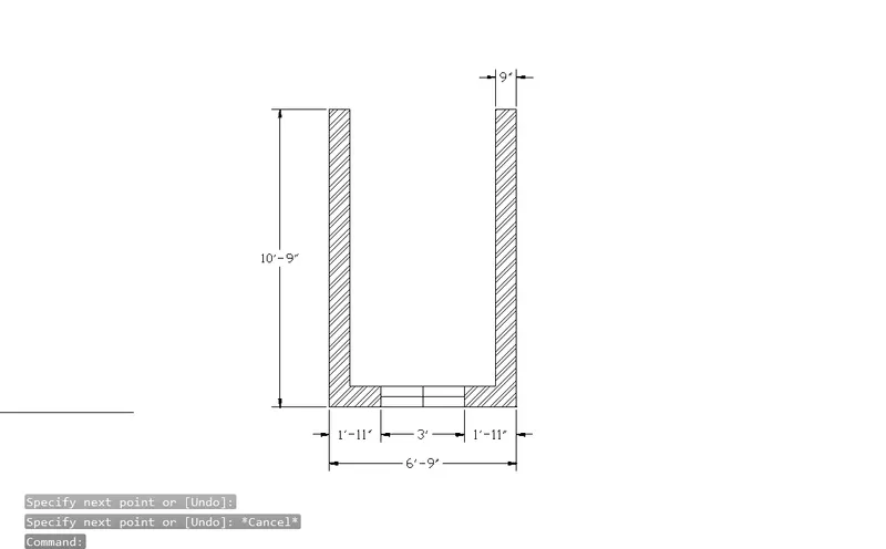
STEP-5
RESULT: THE GIVEN DRAWINGS ARE COMPLETED WITH THE GIVEN FIGURE.AFTER MAKING THE DRAWING FINAL DRAWING SCREENSHOTS ARE ATTACHED WITH THE RESULTANT DRAWING. THE LINK TO THE DRAWING OF AUTOCAD IS ALSO ATTACHED FOR REFERENCE.
AUTOCADE DRAWING FILE LINK:
https://web.autocad.com/acad/me/sid/shares/drawings/07658602-d8b8-4b18-a371-8a227b51ab9c/editor
https://web.autocad.com/acad/me/sid/shares/drawings/07658602-d8b8-4b18-a371-8a227b51ab9c/editor
RESULTANT DRAWING:
QUESTION NO -03
ANSWER :
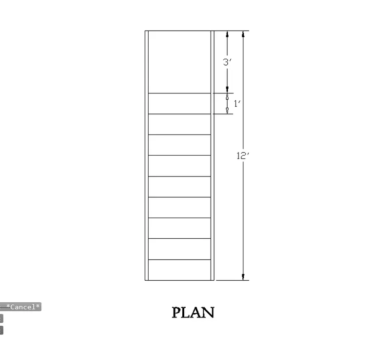
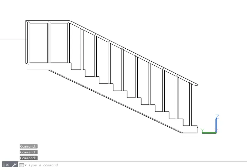
AIM: CREATE THE ISOMETRIC 3D VIEW OF A STAIR WITH RAILING AS SHOWN IN THE PLAN AND ELEVATION. ASSUME THE SIZE OF THE BALUSTRADES AND THE HANDRAILS.
INTRODUCTION: IN THIS CHALLENGE WE HAVE TO DRAW THE 3D MODELLING OG GIVEN FURNITURE WITH THE USE OF AUTOCAD 3D
START THIS DRAWING FIRST OF ALL WE HAVE TO DO SOME SETTINGS ACCORDING TO THE DRAWING -
SOFTWARE SETTINGS
DRAWING-LINK:
https://web.autocad.com/acad/me/sid/shares/drawings/cbfecd80-bdad-4c11-a6f7-c2f6d5b40bba/editor
SETTINGS - OPEN AUTOCAD
- SET DEFAULT SETTINGS - IMPERIAL UNIT (FEET AND INCHES )
- SELECT A TEMPLATE - ACCORDING TO DRAWINGS
- SELECT A WIZARD - ADVANCED SETUP
- UNITS - DECIMAL
- ANGLE - DECIMAL DEGREES
- ANGLE MEASURE - ACCORDING TO THE PLAN
- ANGLE DIRECTION - COUNTER-CLOCKWISE
- AREA - ACCORDING TO THE PLAN
After this enter "D" for the dimension unit and set primary unit ARCHITECTURAL set precision 0'-0"
GO TO WORKSPACE SWITCHING - SELECT 3D MODELLING
MODES -
- GRID ON BY F7 'CONTROL+G'
- USE ORTHO MODE FOR STRAIGHT 90-DEGREE ACCORDING TO NEED(F8)
- ON POLAR TRACKING (F10) SET ANGLE (15,30,45)
- OBJET SNAP TRACKING (F11)
- OBJECT SNAP (F3)
- TRANPARANCY ON WHEN YOU NEED
OTHER DATA:
PROCEDURE: TO DRAW THE LAYOUT PLAN WE FOLLOW THE FOLLOWING STEPS: -
STEP-1
- To draw the stair we have to draw the rectangle with the help of the line command
- Now draw the rectangle 3'x12" (TOP VIEW)
- Now take offset command and tale offset 1.5" internal side
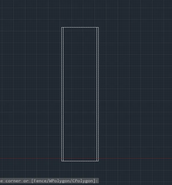
STEP-2
- Now with the help of offset set command take an offset of 3' for landing
- Again take offset 1' from the landing for a thread of the stair
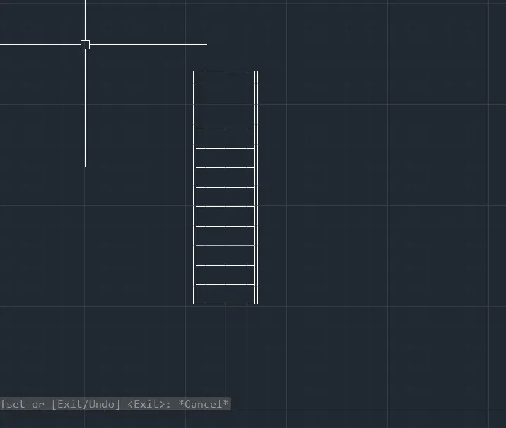
STEP-3
- Now click on the navigation wheel and move this in the isometric view.
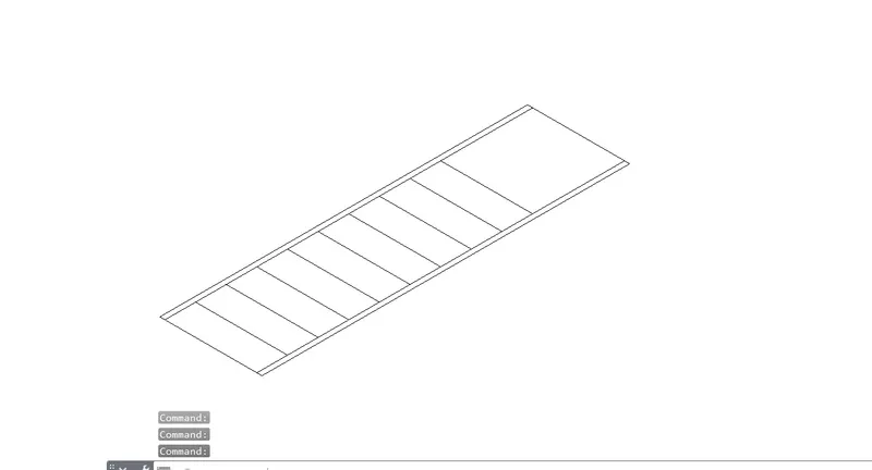
STEP-4
PRESSPUSS
- Now start to draw the 3d stair of the 2d plan
- Take the press pull command and start pulling the stairs.
- Press the stairs with the multiple of 6". (like 6", 12" ,18" ,24" .............)
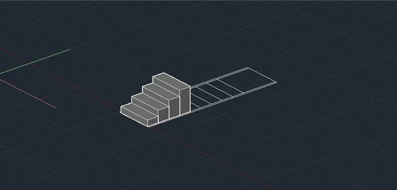
STEP-5
- After pressing the stair with the help of the press pull command we get this.
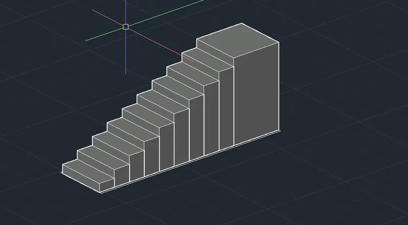
STEP-6
- with the help of line command draw the down part of the stair for removing the below portion of the stair
- Again take the press pull command and remove the below portion of the stair. with the help of the Press pull command
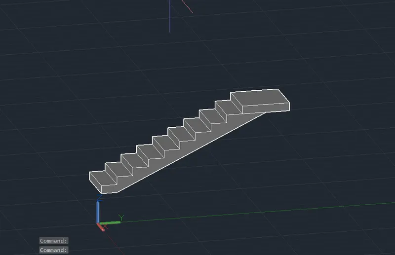
STEP-7
- Now Take line command and connect this stair's first corner to the landing corner.
- Again take line command and connect the corner and landing of the stair with the help of line command.
- Now select both lines and Take copy command to copy both lines vertically with the a distance of 3'
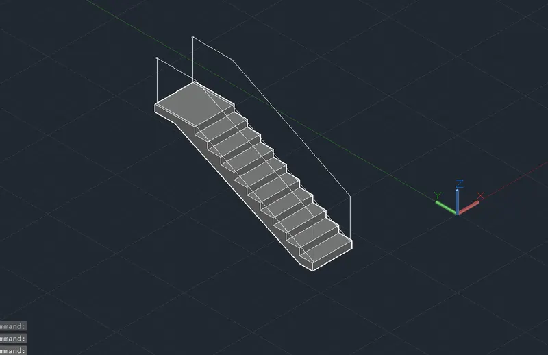
STEP-8
SWEEP-COMMAND
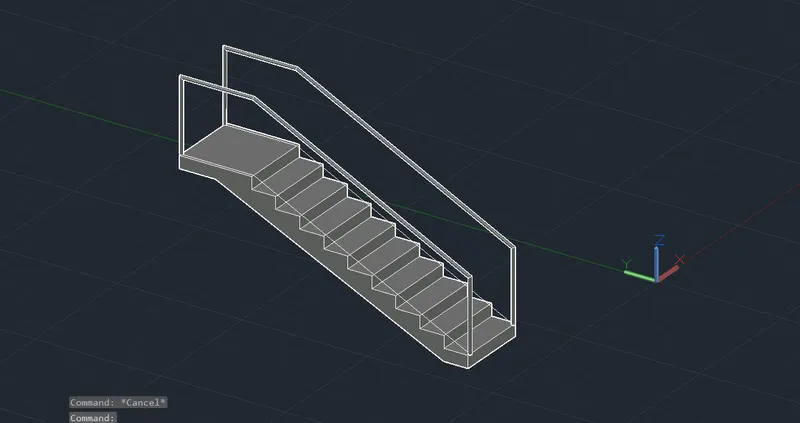
- Now we start to create the railing pipe
- To this take circle command and draw the circle in both upper corners of the line.'
- Now select the circle and go to sweep command select sweep command and click on the path of the pile.
STEP-9
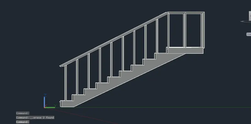
- Now We start to create the vertical pipe of the stair
- Explode the corner of the stairs and select both sides vertical pipe
- Go to array path command and put this
- Now set the distance 12" and set it correctly
STEP-10
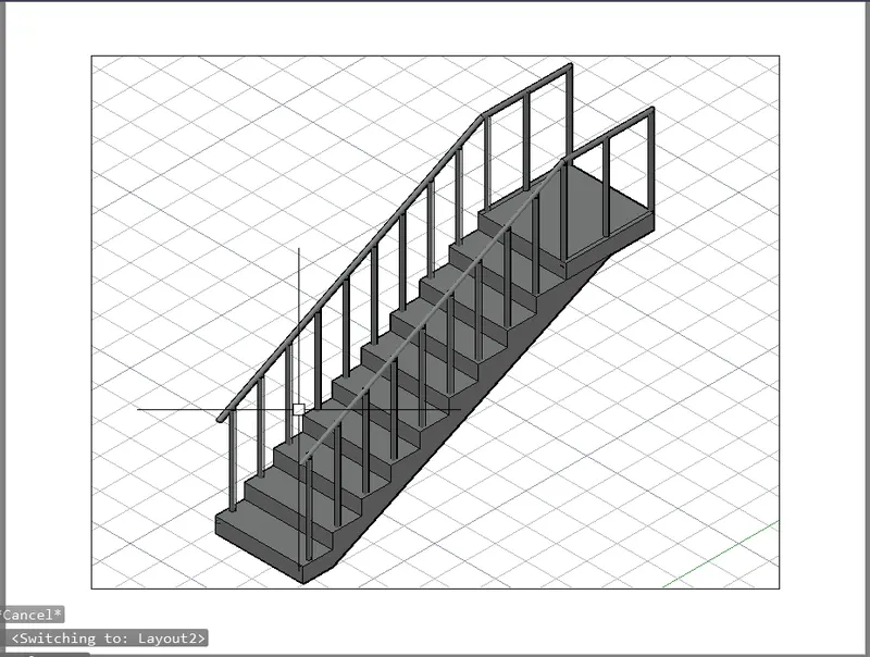
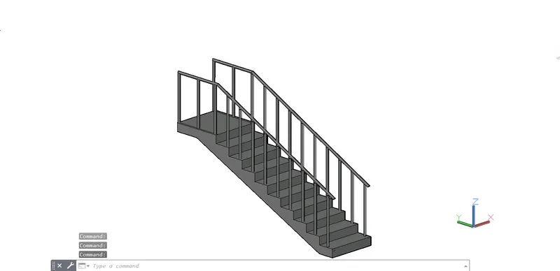
ISOMETRIC VIEW: OF THE STAIR
Now We can see the stairs with railing are completed Go to a different layout and different view.
STEP-11
PLAN OF THE STAIR:
STEP-12
SIDE ELEVATION:
RESULT: THE GIVEN DRAWINGS OF STAIR WITH RAILING ARE COMPLETED WITH THE GIVEN FIGURE.AFTER MAKING THE DRAWING FINAL DRAWING SCREENSHOTS ARE ATTACHED WITH THE RESULTANT DRAWING. THE LINK TO THE DRAWING OF AUTOCAD IS ALSO ATTACHED FOR REFERENCE.
AUTOCADE DRAWING FILE LINK:
https://web.autocad.com/acad/me/sid/shares/drawings/cbfecd80-bdad-4c11-a6f7-c2f6d5b40bba/editor
https://web.autocad.com/acad/me/sid/shares/drawings/cbfecd80-bdad-4c11-a6f7-c2f6d5b40bba/editor
RESULTANT DRAWING:
PLAN
SIDE ELEVATION
ISOMETRIC VIEW:
QUESTION NO -04
ANSWER :
AIM:
INTRODUCTION: IN THIS CHALLENGE WE HAVE TO DRAW THE 3D MODELLING OG GIVEN FURNITURE WITH THE USE OF AUTOCAD 3D
START THIS DRAWING FIRST OF ALL WE HAVE TO DO SOME SETTINGS ACCORDING TO THE DRAWING -
SOFTWARE SETTINGS
DRAWING-LINK:
https://web.autocad.com/acad/me/sid/shares/drawings/a55c40ee-e8f4-459d-a26a-f871c38fe4a8/editor
SETTINGS - OPEN AUTOCAD
- SET DEFAULT SETTINGS -METRIC (mm )
- SELECT A TEMPLATE - ACCORDING TO DRAWINGS
- SELECT A WIZARD - ADVANCED SETUP
- UNITS - DECIMAL precision 0
- ANGLE - DECIMAL DEGREES
- ANGLE MEASURE - ACCORDING TO THE PLAN
- ANGLE DIRECTION - COUNTER-CLOCKWISE
- AREA - ACCORDING TO THE PLAN
After this enter "D" for the dimension unit and set primary unit ARCHITECTURAL set precision 0'-0"
GO TO WORKSPACE SWITCHING - SELECT 3D MODELLING
MODES -
- GRID ON BY F7 'CONTROL+G'
- USE ORTHO MODE FOR STRAIGHT 90-DEGREE ACCORDING TO NEED(F8)
- ON POLAR TRACKING (F10) SET ANGLE (15,30,45)
- OBJET SNAP TRACKING (F11)
- OBJECT SNAP (F3)
- TRANPARANCY ON WHEN YOU NEED
OTHER DATA:
PROCEDURE: TO DRAW THE LAYOUT PLAN WE FOLLOW THE FOLLOWING STEPS: -
STEP-1
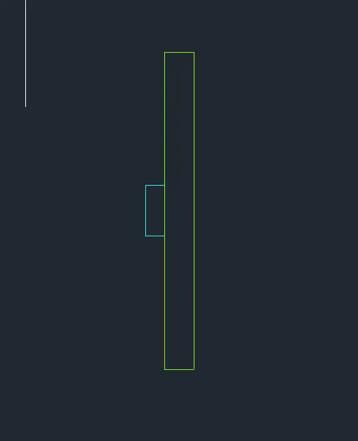
- To Draw the wall footing take line command on 2d face and draw the 2d plan of the given drawing.
- take line command and draw the rectangle with 700mmx 5150mm
- take first side center of the line and draw the chajja portion. dimenttion 4500 mmx950.
STEP-2
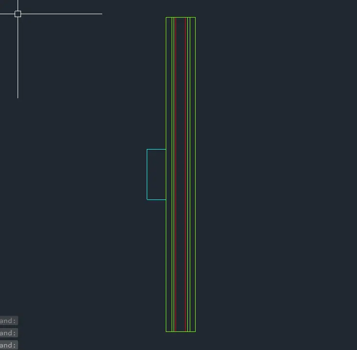
- Now Take center line of the rectangle. and take offset 50 mm both side
- Again Take offset 50mm for the footings.
STEP-3
- Go to isometric view and start with the presspull command to pull the inner object of the rectangle.(5150mm)
- Again take presspull command and take upward 1100 mm
- Again take presspull for bottom footing 700 mm
- again take 300 pull the last footing design.
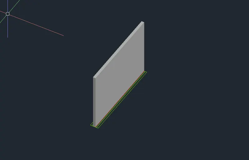
STEP-4
- With help of the presspull command pull all the given object
- To draw the chajja of the object take the sweep command.
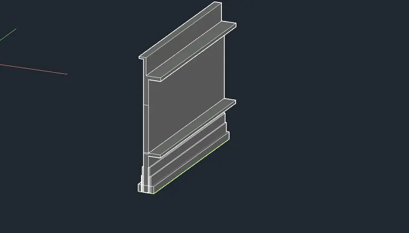
STEP-5
REALISTIC VIEW:
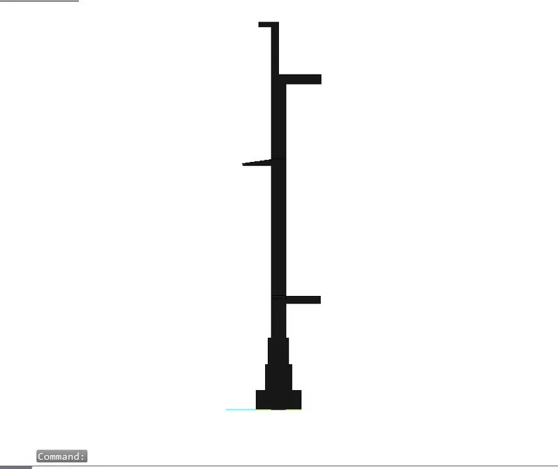
STEP-6
SECTION VIEW OF WALL FOOTING:
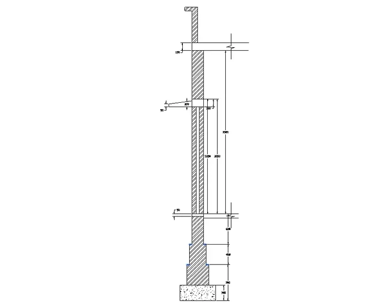
STEP-7
PLAN OF WALL FOOTING:
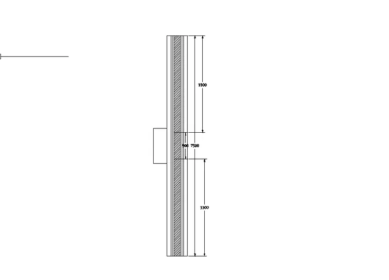
STEP-8
ISOMETRIC VIEW OF WALL FOOTING:
RESULT: THE GIVEN DRAWINGS IF WALL FOOTINGS ARE COMPLETED WITH THE GIVEN FIGURE.AFTER MAKING THE DRAWING FINAL DRAWING SCREENSHOTS ARE ATTACHED WITH THE RESULTANT DRAWING. THE LINK TO THE DRAWING OF AUTOCAD IS ALSO ATTACHED FOR REFERENCE.
AUTOCADE DRAWING FILE LINK:
https://web.autocad.com/acad/me/sid/shares/drawings/a55c40ee-e8f4-459d-a26a-f871c38fe4a8/editor
https://web.autocad.com/acad/me/sid/shares/drawings/a55c40ee-e8f4-459d-a26a-f871c38fe4a8/editor
RESULTANT DRAWING: