Creating 3D Isometric view of various structural elements in AutoCAD
QUESTION-1:
Create a 3D isometric View of the building with plan and elevatio given.
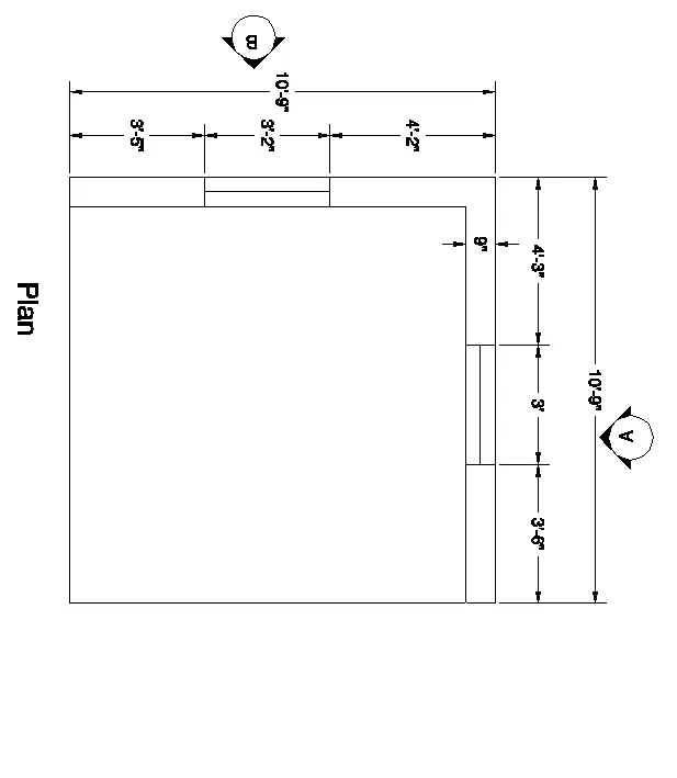
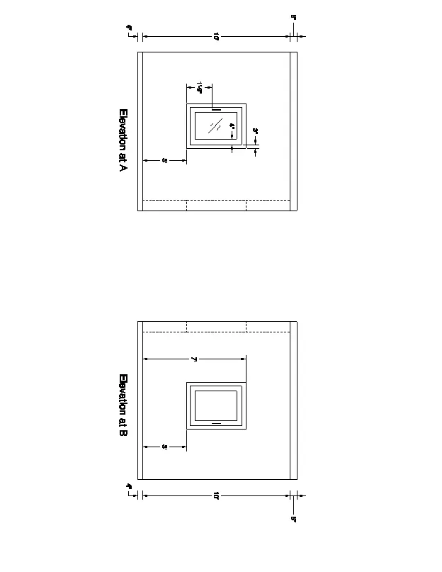
ANSWER:
AIM: To create a 3D isometric view of the given building with plan and elevation.
INTRODUCTION:
- An isometric drawing is a 3D representation of an object,room building or design on a 2d surface.
- One of the defining characteristics of an isometric drawing compared to other types of 3d representation is that the final image is not distorted.
- This is due to the fact that the foreshortening of the axes is equal.
- In an isometric drawing the object appears as if it is being viewd from abve from one corner with the axes being set out from this corner point.
- Isometric drawings begain with one vertical line along which two points are defined.
- Any lines set out from these points should be constructed at an angle of 30 degrees.
COMMANDS USED:
- Line.
- Rectangle.
- UCS
- Dimlinear.
- Region
- Extrude.
- Box
- Subtract.
- Units
- Dimstyle.
- 3D face command.
- 3D orbit command.
- Hide command
- Expolde
- Move command.
- Copy command.
- Dist command.
- Solidedit coomand.
- Union command.
- Boundary command.
- 3D miror command.
- 3D rotate command.
- Erase command.
- Plan command.
PROCEDURE:
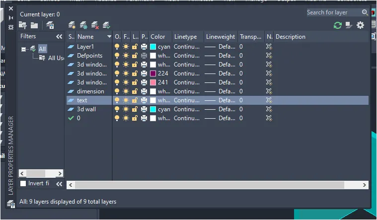
STEP-1: Creating Layers
- Open Layer properties and crete new layers by clickingon new layer or right click on any layer and select new layer to create new layer.
- Layers are created as follows.
STEP-2: Creating plan layers.
- Change the current layer to 3d wall
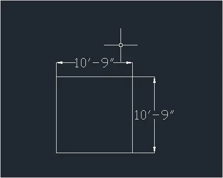
- Create a rectangle of dimensions 10'9"*10'9" at any point on the screen.
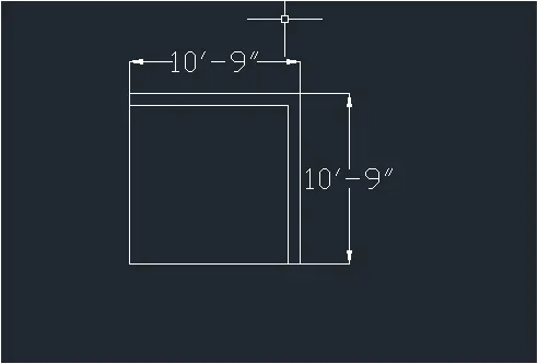
- Offset the rectangle to inside to distnace of 9" and as wall thickness.
- Delet the left and bottom lines ane extend them to the edges as shown in figure.
- Change the current layer to 3D window frame.
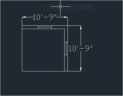
- Draw the window witn dimensions 3'2" at top and 3' on right side shown in figure.
STEP-3: Creating 3D View.
- Change the view to 3d by clicking on home buttion of view cube.
- Set UCS as world.
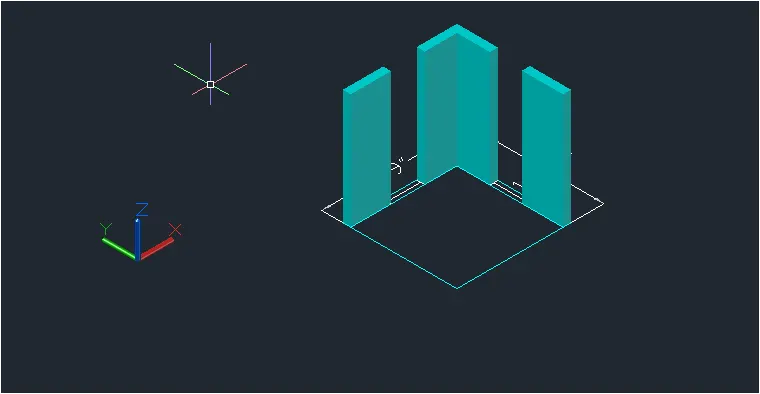
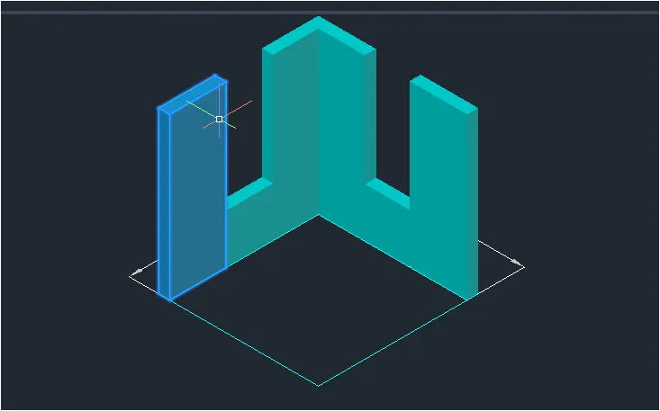
- Create the boundaries for the walls using 'BO' command.
- Extrude the bounderies creted to total height of 10'10".
- Select all the wall and use group command to group then together.
STEP-3(a):
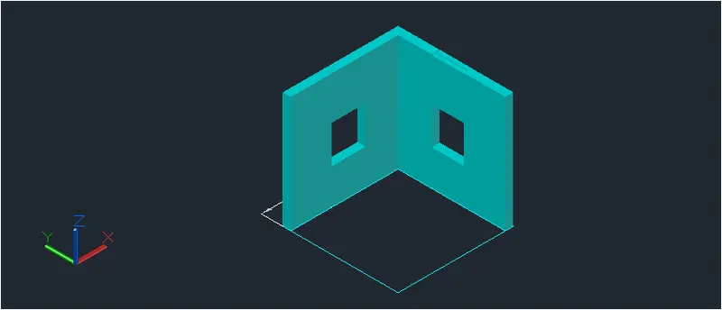
- Draw rectangle at both windows and change them to bounderies using boundary command.
- Extrude both rectangles drawn to height of 3'4" as shown in the figure.
- Draw rectangles at top of both window openings and change them to boundaries using boundary command.
STEP-4: Creating Elevation Windows.
WINDOW AT ElEVATION A.
A)Change the current layer to 3d window frame.
- Type ucs and click on face and select the face having 3' wide window.
- Draw a recatngle of dimension @3'4'.
- Offset the recatngle to inside to distnace of 3"
- Offset the offset recatngle to inside to distance of 4"
- Start the boundary command and click on pick points
- Click inside the window frame area and press enter.
B) Change the current layer to 3D window mulion
- Start the boundary command and click on pick points.
- Click inside the window mulion area and press enter.
C) Change the current layer to 3d window glass.
- Start the bounadry command and click on pick points.
- Click inside the window glass area and press enter.
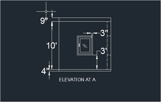
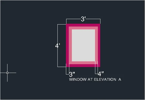
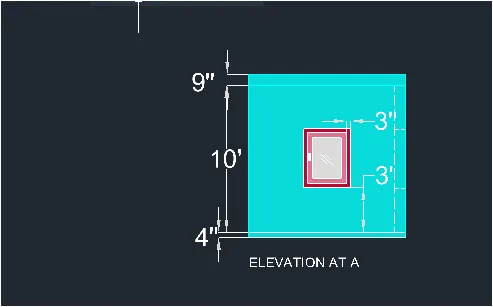
- All the layers are extrude to give window projection look as shown in figure.
WINDOW AT ELEVATION B.
- Type UCS and click on face and select the face having 3'2" wide window.
- Draw a reactngle of dimesion @3'2",4'.
- Offset the rectangle to inside to distance of 3".
- Offset the offset recatngle to inside to distance of 4"
- Start the boundary command and click on pick points
- Click inside the window frame area and press enter.
B) Change the current layer to 3D window mulion
- Start the boundary command and click on pick points.
- Click inside the window mulion area and press enter.
C) Change the current layer to 3d window glass.
- Start the bounadry command and click on pick points.
- Click inside the window glass area and press enter.
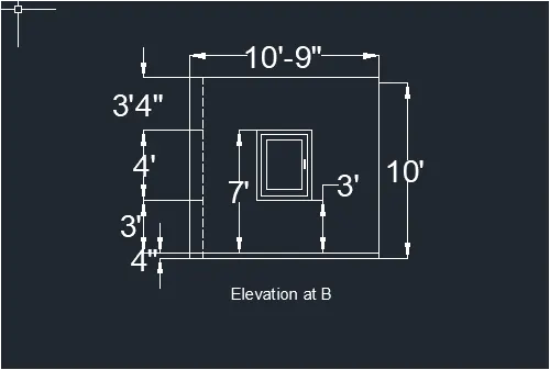
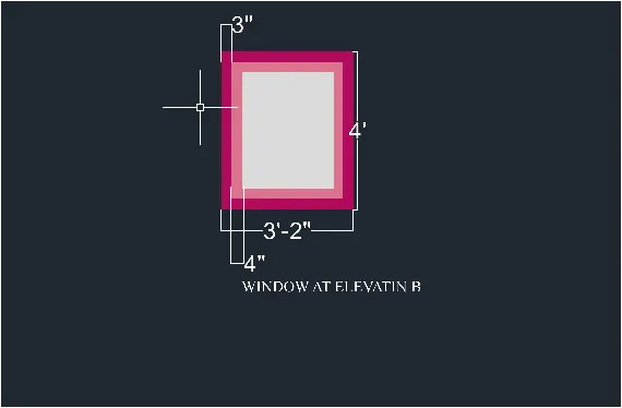
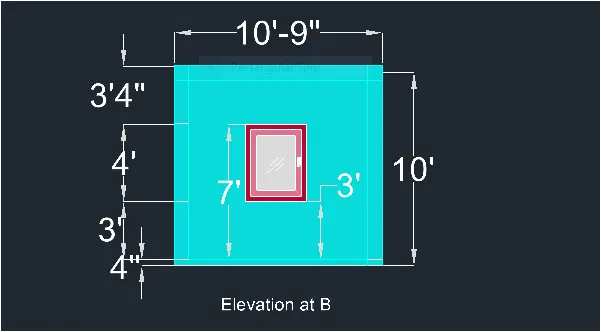
- All the layers are extrude to give window projection look as shown in fig.
STEP-5: Creating Views.
- Click on home buttion of the view cube and zoom for better view.
- Go to visuvilise tab and click on new view
- Set view name as view1
- Click on current l view and press ok.
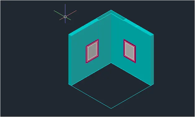
- Click on the NE ISOMETRIC view of the view cube and zoom for better view.
- Go to visuvilise tab and click on new view
- Set view name as view2
- Click on cuurent view and press ok.
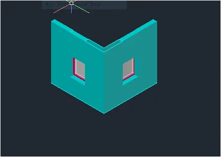
RESULT:
- Initially all the layers necessary are created with respective line types and line weights.
- Then plan view is drawn as shown in step2 then from the step-3 the 3d view is created with respective layers assigned.
- The UCS view is changed sccordingly to make changes to the 3d view and 3d dimensions..
- Boundary command is used for creteing aling the bounderoes and extruding the after the view are created for showing result.
- The result consist of different views of the 3D modek such as sw isometric view,NE isometric view right side view Windows.
- All dimensions are in Feet and inches.
- Text and dimensions are added with respective layers.
SW ISOMETRIC VIEW
NE ISOMETRIC VIEW
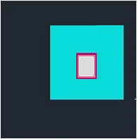
WINDOW AT ELEVATION
RIGHT SIDE VIEW
QUESTION-2:
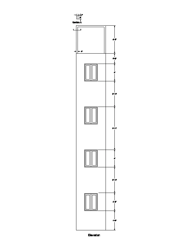
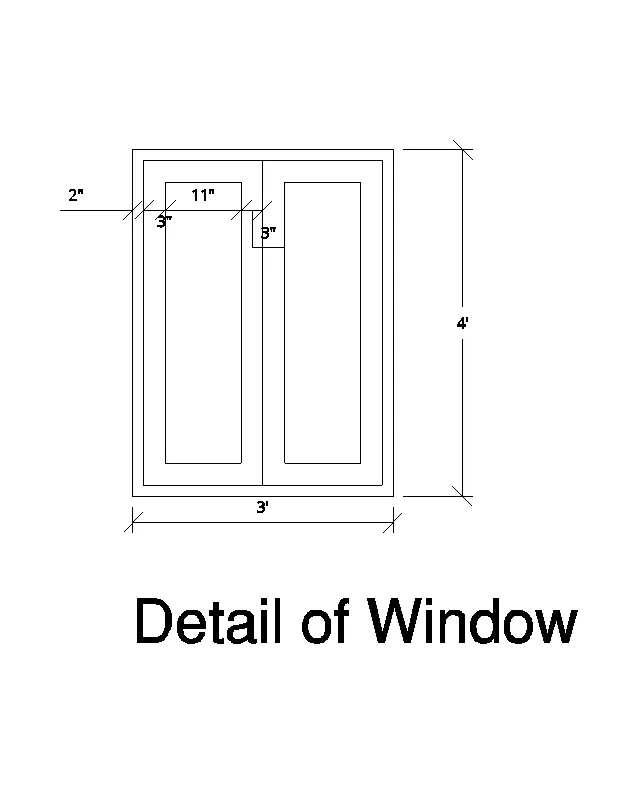
Create the 3D view of the building Fceade as given in the plan and elevation also see the details of the plan and window.
ANSWER:
AIM: To draw the 3d building Facade as given in the plan and elevation.
INTRODUCTION:
- A plan view of wall and two elevation views one is of a window details and second is of floorlevell elevation are given and they are to be converted into a 3D model
- One window opening on front side is given with detials regarding the frame dimensions two mullion dimensions.
- The height of floor is given as 9'11" four floor building with similar dimension is made in 3d view.
- Height of window from the floor level of each floor is gien as 4'6".
PROCEDURE:
- OPEN AUTOCAD
- In startup settings start from scrach select imperical ( feet and inches).
- Change snap and grid spacing to 1'
- Change majior line every grid line to 10.
- Turan off adaptive grid.
- Type un in command box and press enter.
- change units type to ENGINEERING and precision to 0'-0.0" and insertion scale to inches.
- change the workspace setting autocad from drafting and annotation to 3d modeling.
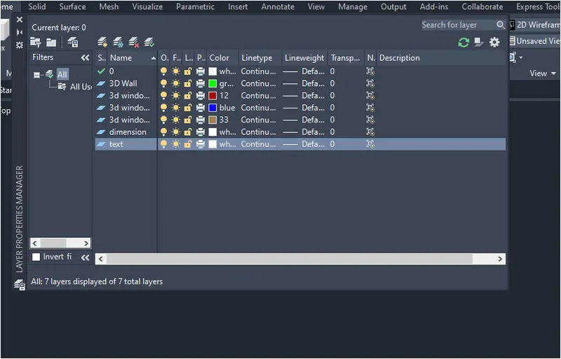
STEP-1: Creating lyers
- Open Layers propertites and crete new layers by clicking on new layer or right click on any layer and select new layr to crete new layer.
- Layer are created as follows.
STEP-2: Creating 2D Plan view.
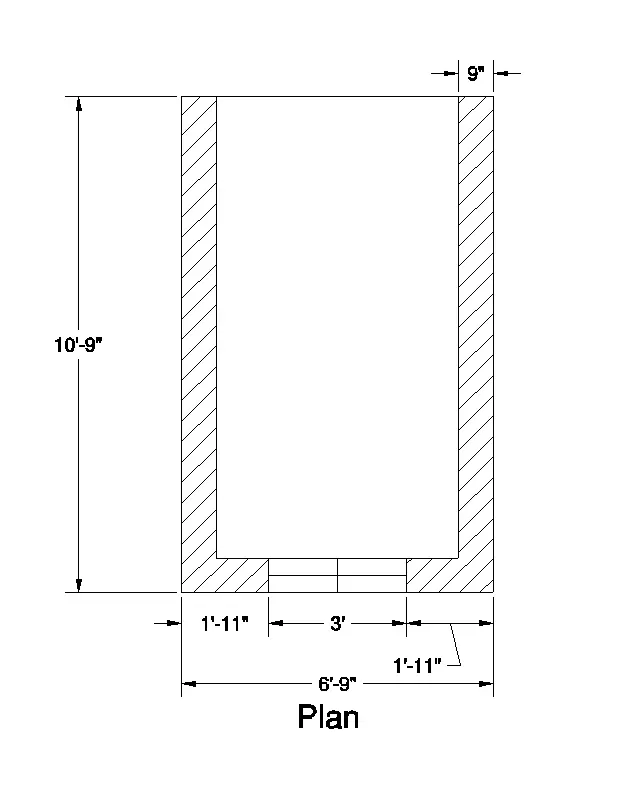
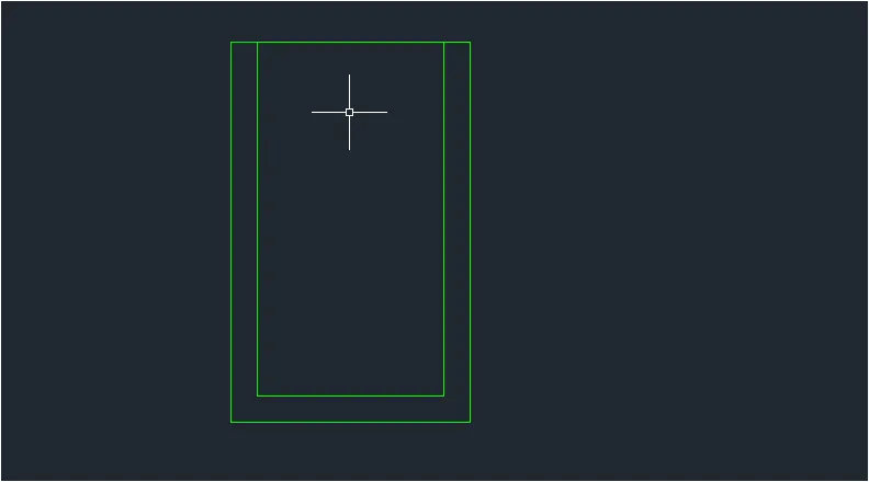
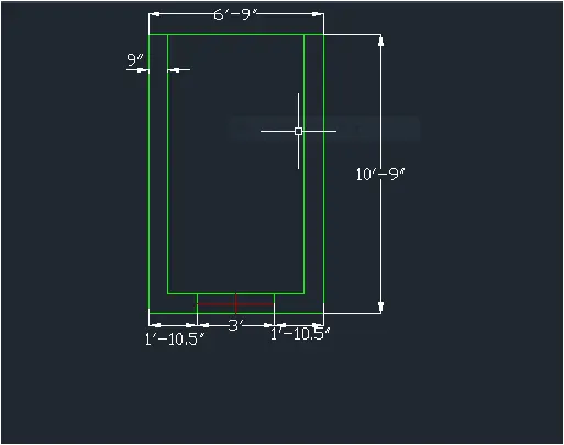
- Create a recatngle of dimensions 6'9"*10'9" at any point on the screen.
- Offset the recatngle to inside to distance of 9" as wall thickness.
- Explode the rectangles drawn
- Delet the top line and extend them to the edges.
STEP-2(a)-
- Change the current layer 3D Window frame
- Create the window opening of dimensions 3' wide as shown in figure.
- Add dimensions are drawn using dimension layer.
STEP-3: Creating 3D view
- Change the view to 3d by clicking on home button of view cube.
- Set UCS as world
- Set the view style control as REALISTIC.
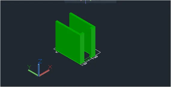
- Create the boundaries for the walls using "BO' command
- Extrude the boundaries cretaed to total height of 10'10"
- Select all the wall and use group command to group then together.
- Delete the window lines.
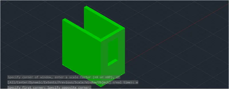
- Create a boundry region over the window lines.
- Extrude the boundary to a height of 4'6".
- Draw a rectangle on top of the window opening using rectangle command.
- Chanhe the rectangle into a region.
- Extrude the region to distance of 1'3" to below and then window openin is creted as shown in figure.
STEP-4 : Creating Elevation Windows
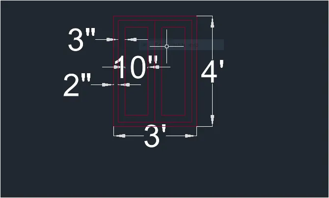
4' WIDE WINDOW.
- Change the current layer to 3D window frame.
- Type UCS and click on face and select the face having 3' wide window.
- Draw a recatngle of dimension @3'4'
- Offset the rectangle to inside to distance of 2"
- Offset the offset recatngle to inside to distance of 3"
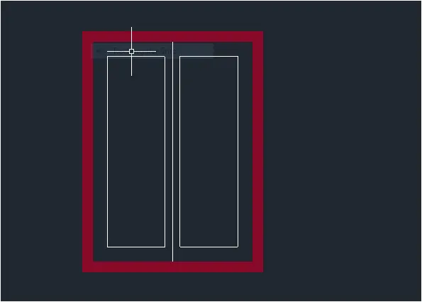
- Draw center line connecting midpoints
- Offset the lines to both sides to a diatnce of 3"
- Trim all the unnecessary edges.
- Start the boundary command and click on pick points.
- Click inside the window frame area and press enter.
- Start SUBTRACT command.
- Slect the bigger region and then select the smaller regions to subtract them.
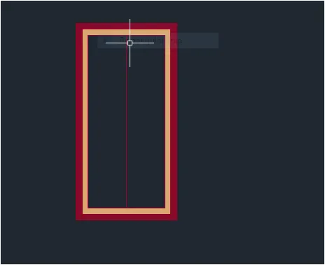
- Change the current layr to 3D window Mulion.
- Start the boundary command and click on pick points.
- Click inside the window mulion area and press enter.
- Start SUBTRACT command.
- Select the bigger region and then select the smaller glass region to subtract it.
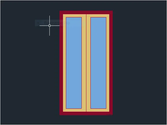
- Change the current layer to 3d window glass
- Start the boundary command and click on pick points.
- Click inside the window glass area and press enter.
- All the layers are extrude to give windoe projection look as shown in figure.
STEP-5 Creating Elevation View.
- The window creted in step-4 are placed at its positions.
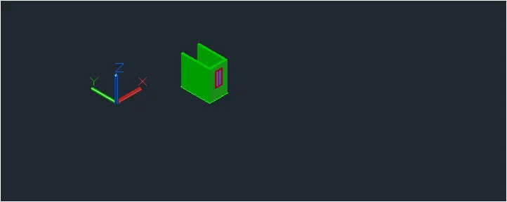
- Group all the items to crete the elevation view.
- Copy the block having 4' height window and place it 3 times as shown in figure.
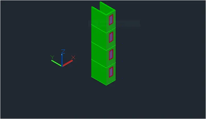
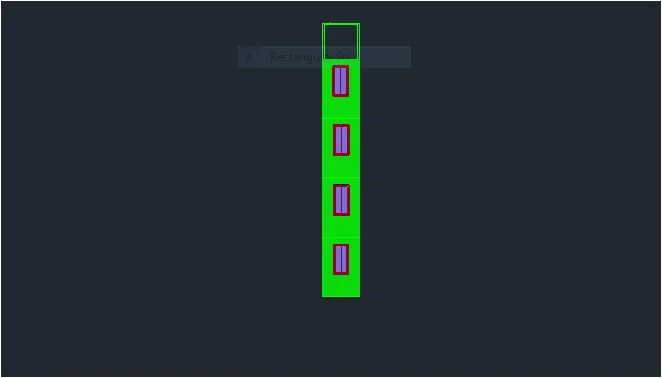
- Create the top part of the drawing using 4" wall with height 6'5" from top.
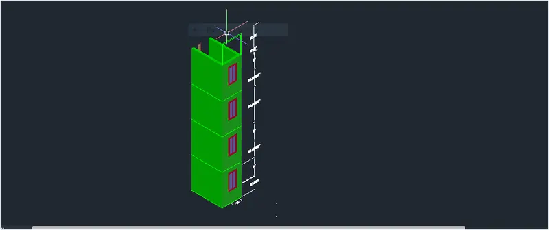
RESULT:
- Intially all the layers neceassary are created with respective line types and line weights.
- Then plan view is drawn as shown in step2 then from the step-3 the 3d view is created with respective layers assigned.
- The UCS view is changed sccordingly to make changes to the 3d view and 3d dimensions..
- Boundary command is used for creteing aling the bounderoes and extruding the after the view are created for showing result.
- The result consist of different views of the 3D modek such as sw isometric view,NE isometric view right side view Windows.
- All dimensions are in Feet and inches.
- Text and dimensions are added with respective layers.
1. VIEW1 ( SW ISOMETRIC VIEW).
2. VIEW2 ( FRONT VIEW).
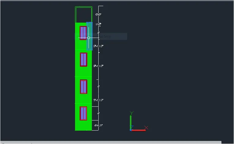
3. VIEW3 ( TOP VIEW).
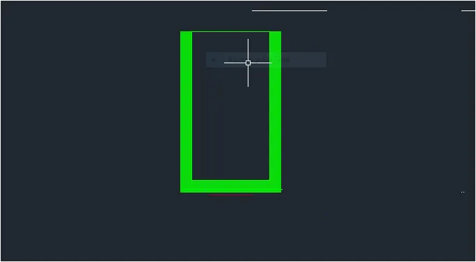
4. VIEW4-RIGHT SIDE VIEW
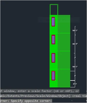
5. Windows
QUESTION-3:
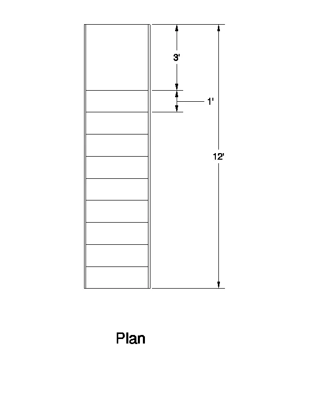
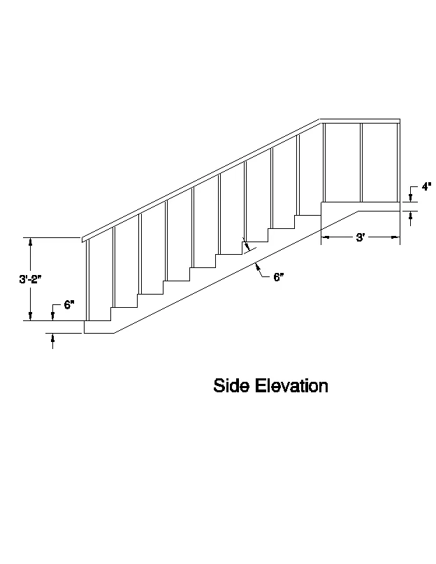
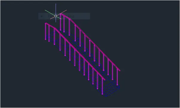
Create the isometric 3d view of a stair with railing as shown in the plan and elevation Assume the size of the balustrades aand the hand rails.
ANSWER:
AIM: To draw the 3d view of a stair with railing as shown in the plan and elevation.
INTRODUCTION:
- A plan view and elevation view of stair case are given and they are to be converted into a 3d model.
- Plan view consists of number of stairs in the staircase and their horizontal dimensions of stair case .
- Elevation view consist of staircase side view and vertical dimensions of staircase and stair case components such height of hand rails and their spacing in the landing.
- Thickness of stiar slab is given as the box some other components of the stiar told to be assumed the assume dimensions are as follows.
- Dimensions of vertical rails is 1" diameter.
- Dimensions of hand rails is 2" diameter.
PROCEDURE:
- OPEN AUTOCAD
- In startup settings start from scrach select imperical (FEET AND INCHES).
- Change snap and grid spacing to 1'
- Change majior line every grid line to 10.
- Turan off adaptive grid.
- Type un in command box and press enter.
- change units type to ENGINEERING and precision to 0'-0.0" and insertion scale to inches.
- change the workspace setting autocad from drafting and annotation to 3d modeling.
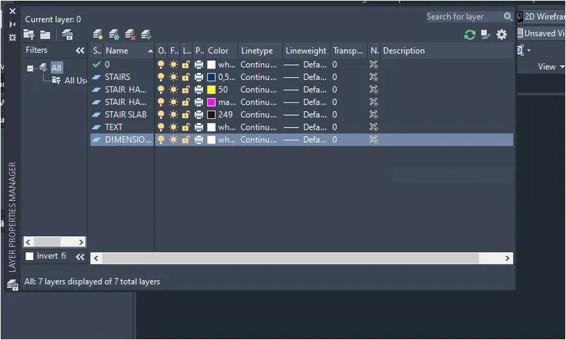
STEP-1: Creating lyers
- Open Layers propertites and crete new layers by clicking on new layer or right click on any layer and select new layr to crete new layer.
- Layer are created as follows.
STEP-2: Creating 2D Plan View of staircase.
- Change the curent layer to stiars.
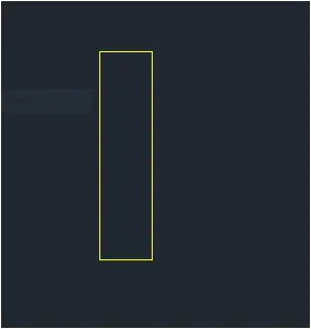
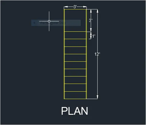
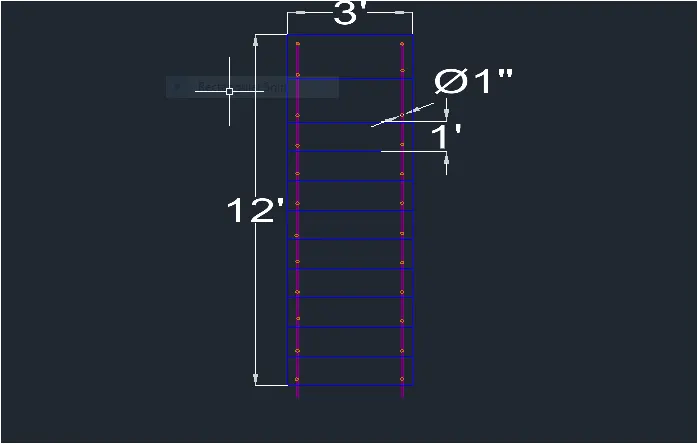
- Draw a rectangle of dimensions 3'*12'.
- Expolde the rectangle.
- Offset the side edges to inside to a distance of 1"
- Offset the bottom edge to upside 12 tiimes to a disatnce of 1' as shown in figure.
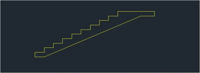
Step-3: CREATING SIDE VIEW.
- Change the view 3d by clicking on home button of view cube and change the view to right side view.
- Set UCS as Right.
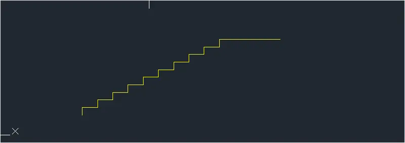
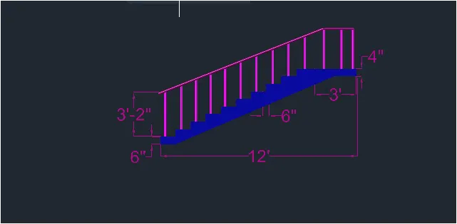
- Start line command and draw a vertical line of length 6"
- Draw a horizontal line of length 1'
- Repeat the same process for 12 times to draw 12 steps.
- After reaching 12 steps draw a landing of length of 3'.
- Draw a line of 1' at the bootom step.
- Draw a line of 6" at the top right edge of landing.
- Draw a line of 1'6" backwards.
- Draw a slab joining the lines.
STEP-4: CREATING 3D VIEW.
- Change the view to 3d by clicking on home button of view cube.
- Set UCS as world.
- Set the view style control as REalistic.
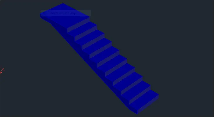
- Create a region from the side view of the stairs.
- Extrude the side to a distance of 3' as shown in figure.
STEP-5: HAND RAILS:
- Change the current layer to stair handrails.
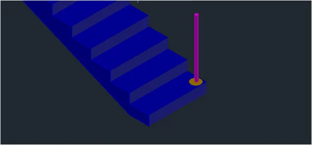
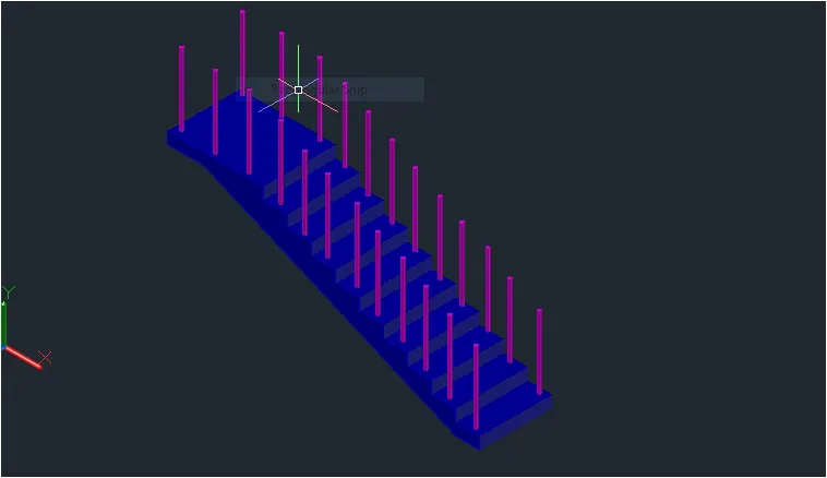
- Draw circle of diameter 1" with 2" offset from the top right edges of the first thread of staircase.
- Change the circle onto a region.
- Extrude the region to aheight of 3'as shown in figure.
- Change the current layer to stair handrails stand.
- Draw a handrail stand at the bottom with diamension 2" and extrude as shown in figure.
- Using copy command copy all hand rail components on all stairs with same offset as shown in figure.
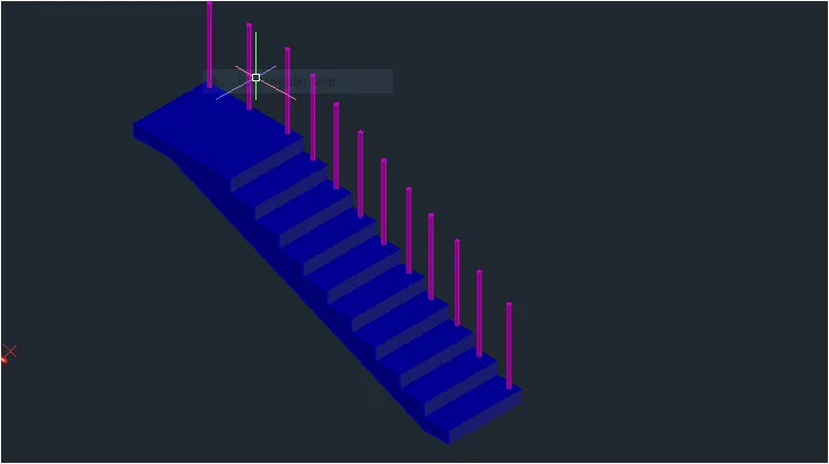
- Copy the same to the other side as shown in figure.
- Change the current layer to stair handrails.
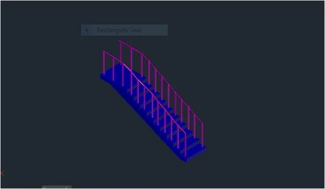
- Draw a polyline connecting all the top edges of hand rails.
- Change the UCS to front.
- Draw a circle of daimeter 2" on top of the first hand rail.
- Create a region of the circle drawn
- Start sweep command.
- Select the circle as object to sweep
- Select the circle as object to sweep.
- Select the polyline drawn as path of sweep as shown in figure.
- Copy the same to the other side.
RESULT:
- Intially all the layers neceassary are created with respective line types and line weights.
- Then plan view is drawn as shown in step2 then from the step-3 the 3d view is created with respective layers assigned.
- The UCS view is changed sccordingly to make changes to the 3d view and 3d dimensions..
- Boundary command is used for creteing aling the bounderoes and extruding the after the view are created for showing result.
- The result consist of different views of the 3D modek such as sw isometric view,NE isometric view right side view Windows.
- All dimensions are in Feet and inches.
- Text and dimensions are added with respective layers.
1- VIEW1( TOP VIEW).
2- VIEW2( RIGHT SIDE VIEW)
3-VIEW3(SW ISOMETRIC VIEW)
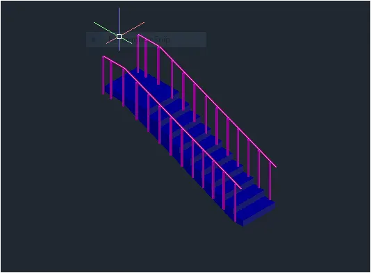
4-VIEW4( FRONT VIEW).
QUESTION-4:
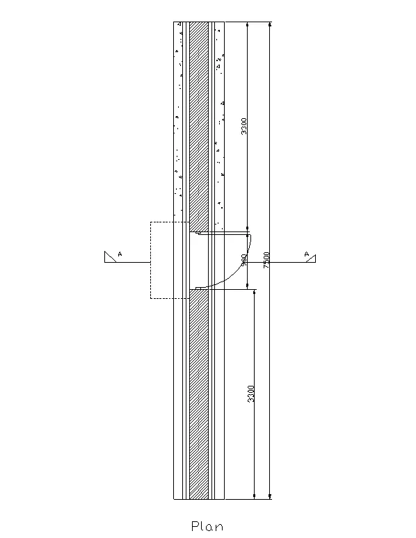
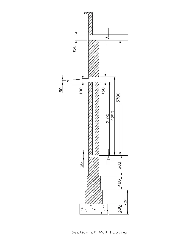
Create the 3d view of a wall with spread footing create the door opening only. Assume the size of the parpet and the details.Also create a renedered view of the model with materials as of your choice.
ANSWER:
AIM: To draw the 3d view of a wall with spread footing as shown in the plan and elevation.
INTRODUCTION:
- A plan view elavtion view of a wall with spread footing under it are given and they are to be converted into a 3d model.
- Spread footing is a typpe of footing which goes all along the length of the wall in a building.
- It Is used as shallow footing type.
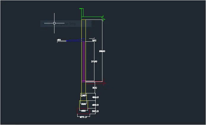
- Plan view consists of vertical diamensions of different levels of footing height of 230mm thickness wall.
- Some other components of the footing are told to be assumed. the assume dimensions are as follows.
- Thickness of wall is assumed as 230mm.
- Thickness of level 1 of footing is same as wall thickness i.e 230mm.
- Coping thikness of level 2 is offset of 50mm than the thickness of wall.
- Thickness of level 3 is offset of 50mm than the thickness of level 2
- Thickness of level 4 is offset of 120 mm than the thickness of level 3.
PROCEDURE:
- OPEN AUTOCAD
- In startup settings start from scrach select imperical ( feet and inches).
- Change snap and grid spacing to 1'
- Change majior line every grid line to 10.
- Turan off adaptive grid.
- Type un in command box and press enter.
- change units type to decimal and precision to 0.0and insertion scale to inches.
- change the workspace setting autocad from drafting and annotation to 3d modeling.
STEP-1: Creating lyers
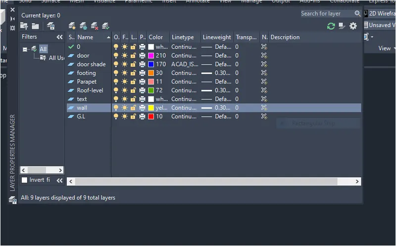
- Open Layers propertites and crete new layers by clicking on new layer or right click on any layer and select new layr to crete new layer.
- Layer are created as follows.
STEP-2: CREATING 2D PLAN VIEW OF WALL WITH SPREAD FOOTING.
- Change the current layer to wall.
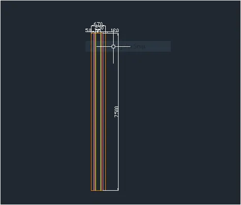
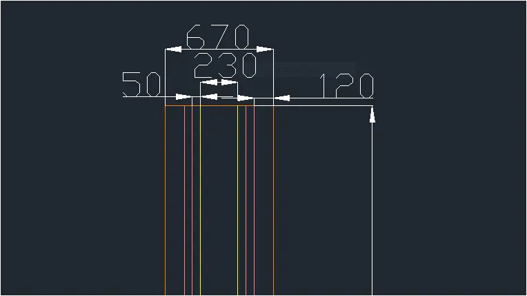
- Draw a rectangle of dimesions 670* 7500
- Offset the offset reactngle inside to distance of 50 mm twice.
- Expolde all the offset reactngle.
- Delet the top and bottom edges of the exploded reactngles.
- Extend all the recatngle to top and bottom edges of outer rectangle.
- AT the end select the nidividual lines and change their layers respectivily
STEP-2: Creating Door Block
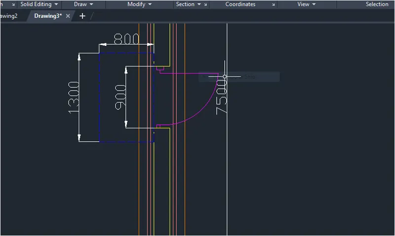
- Draw a reactngle of dimensions 50 *100mm
- Draw another rectangle with dimensions of 50*50mm
- Draw a line of length 850mm from the edge.
- Draw an arc line of the door swing.
- Convert the door into block
- EDit the block and add flip parameters.
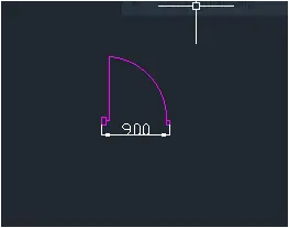
- Create the door opening of 900mm at the middle.
- Add the door block by rotating the door.
- Add the door shade using respective layer
STEP-3: Creating Elevation View
- Click on the front view of the view cube and zoom for better view.
- Change the UCS to front.
- Change the current layer to G.L
- Draw a line of certal length
- Offset the line to bottom 25mm
- Offset the line to bottom 265mm
- Offset the last offset line bottom to diatnce of 100mm
- Change the current layer to wall
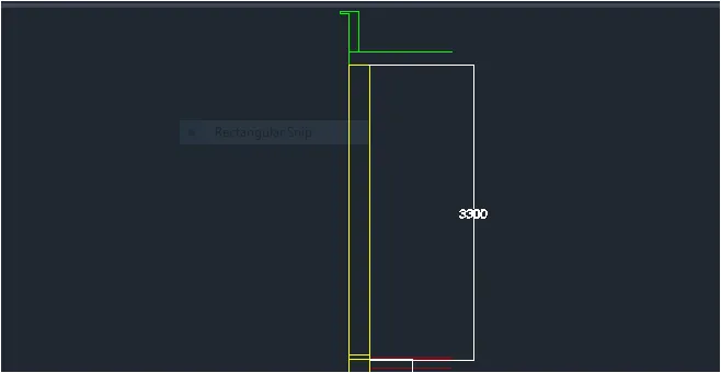
- Draw a rectangle of dimensions230* 3300 from the top left edge of ground level
- Change the current layer to roof level.
- Draw roof of thickness 150mm as shown in figure.
- Draw a parapet wall of height 600 mm as shown in figure.
STEP-4: FOOTING LAYERS
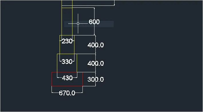
- Draw a reactngle of dimension 230* 600mm, below the floor level as shown in figure.
- Draw a rectangle of dimesion 330*400 below the first level as shown in figure.
- Draw a recatngle of dimaesion430*400mm below the second level as shown in figure.
- Change the current layer to footing.
- Draw a reactngle of dimensions 670* 300mm below the thhird level as shown in figure.
- Trim the unnecessary edges.
DOOR:-
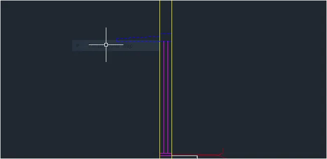
- Change the current layer to door.
- Draw a line along the length of the door of 230mm at the ground level.
- Offset the line to below the ground level.
- Offset the line to distance of 2100 to above.
- Change the cuurent layer to door shade
- Draw the door shade as shown in figure.
- The end result of this step is follows.
STEP-4 CREATING 3D VIEW OF SECTION:
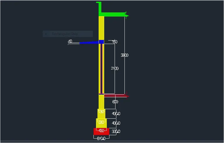
- For creating the 3d view initially boundaries are creted.
- Each boundary is created with its respectivily layer as current layer as shown in the following figure.
EXTRUDING:
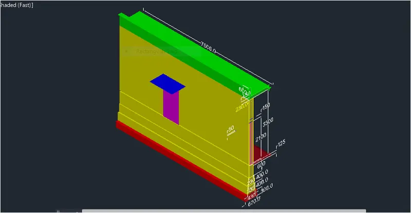
- The created boundaries are to be extrude to a distance of 7500mm.
- Select the bounadaries by changing their respective current layer.
- Door opening is added by drawing a recatngle at the door location from the plan view.
- Then from the extruded part the door region is subtracted from the wall suing subtract command.
- Similarly door shade is created with the opening above.
- After door shade remaning layer is extruded as shown in figure.
RESULT:
- Intially all the layers neceassary are created with respective line types and line weights.
- Then plan view is drawn as shown in step2 then from the step-3 the 3d view is created with respective layers assigned.
- The UCS view is changed sccordingly to make changes to the 3d view and 3d dimensions..
- Boundary command is used for creteing aling the bounderoes and extruding the after the view are created for showing result.
- The result consist of different views of the 3D modek such as sw isometric view,NE isometric view right side view Windows.
- All dimensions are in Feet and inches.
- Text and dimensions are added with respective layers.
1.- VIEW1( SW ISOMETRIC VIEW)
2- VIEW2( RIGHT SIDE VIEW)
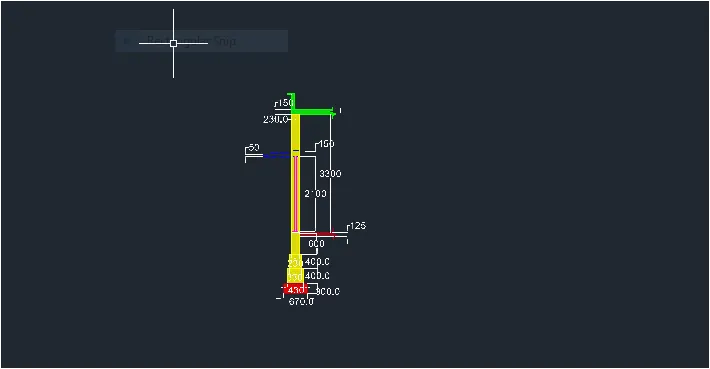
3- CAM1 VIEW
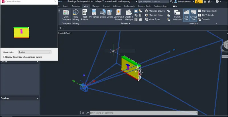
RENDERING:
- Renadering is done by adding materials 3d view.
- Material Browser is used to insert the materials in drawing.
- Material libraries is as per following.
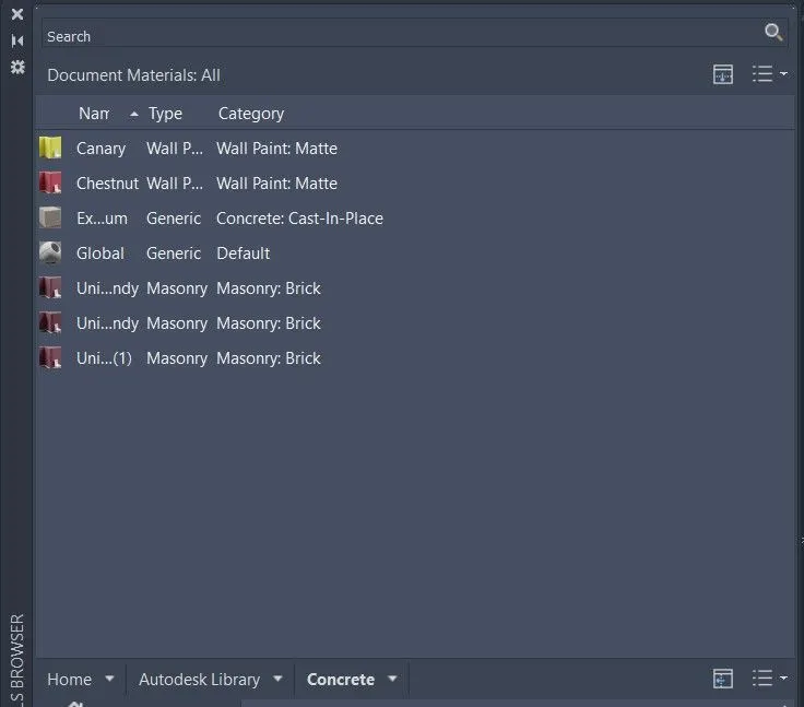
RESULTS FOR RENDERING:-
- Results of rendered drawing is as per following.
RIGHT FRONT VIEW:
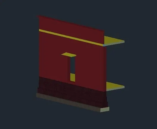
2-LEFT-BOTTOM VIEW
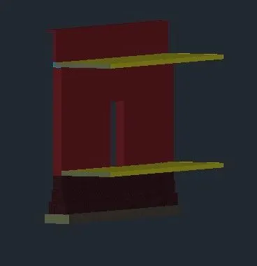
FRONT ELEVATION VIEW
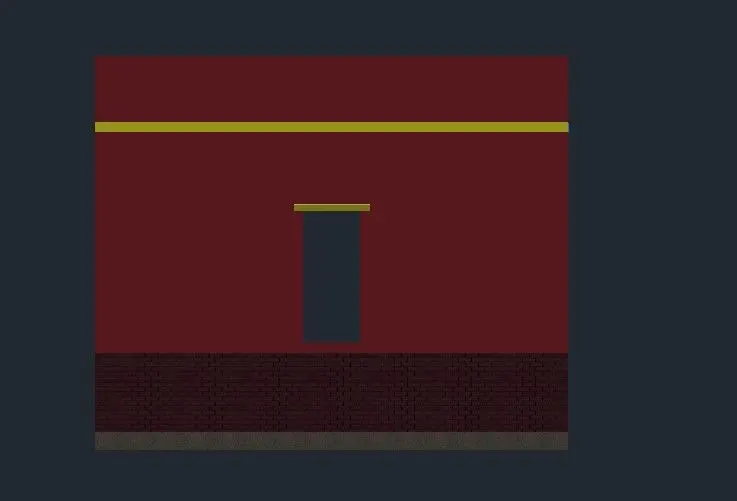
SIDE ELEVATION VIEW