Creating 3D Isometric view of various structural elements in AutoCAD
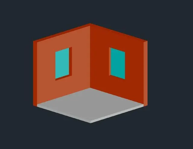
1.) AIM: To create a 3D Isometric View of the building with plan and elevation given.
PROCEDURE:
- Open autocad and the set the maximum and minimum limit.
- Draw a rectangle using the rectangle command according to the question.
- Draw the windows of the size 3' x 4' and 3'-2" x 4' and use extrude command.
- Now draw the walls using the extrude and use differnt layers.
- Finally attach the windows to the walls as shown in the given question.
- Use the 3dorbit command to see the different views of the given figure.
RESULT:
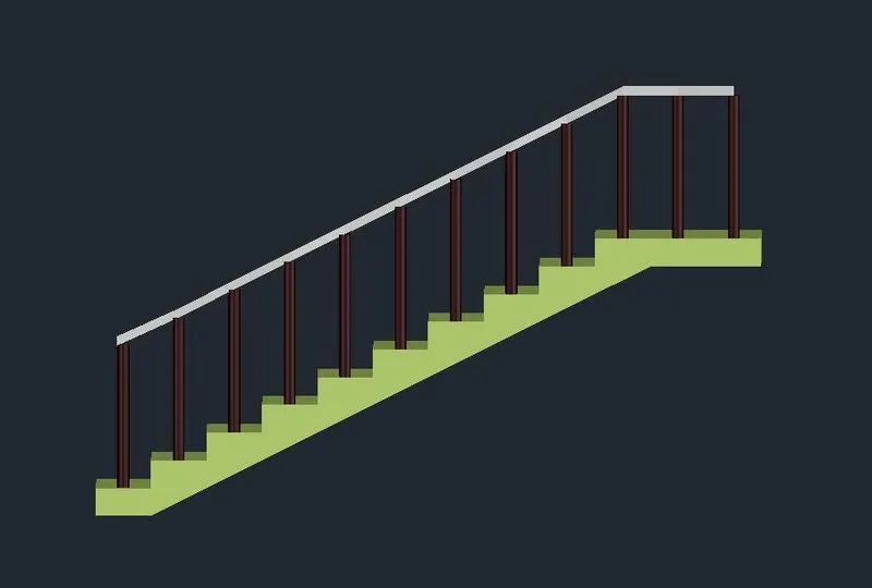
3.) AIM: To Create the ismoteric 3d view of a stair with railing as shown in the plan and elevation.
PROCEDURE:
- Open the autocad and set the maximum and minimum limit.
- Draw the stairs using line command.
- Draw the stairs with the riser of 6" and tread of 1'.
- Use the extrude command to extrude the rotated figure.
- Now draw the railing using the circle and sweep command.
- View the stairs in the side view using the 3drotate command.
RESULT: