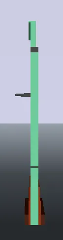
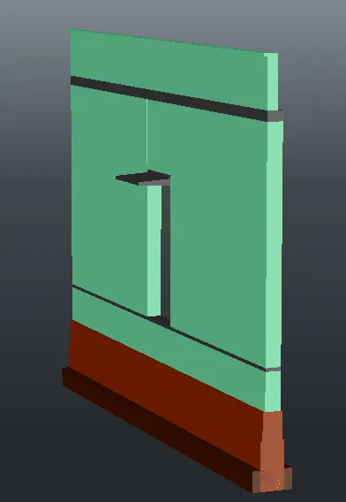
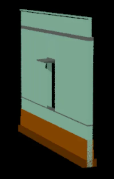
Creating 3D Isometric view of various structural elements in AutoCAD
1.
Aim
To create a 3D Isometric View of the building with plan and elevation given.
Introduction
Create the 3d isometric view of building plan and create windows
Procedure
AutoCAD is opened with Imperial setting as default.
In units of measurement Architectural is selected.
Precision is set to 0'-0.0".
First 2d plan given is drawn
Plan is created with LINE, TRIM, and OFFSET commands as per dimensions
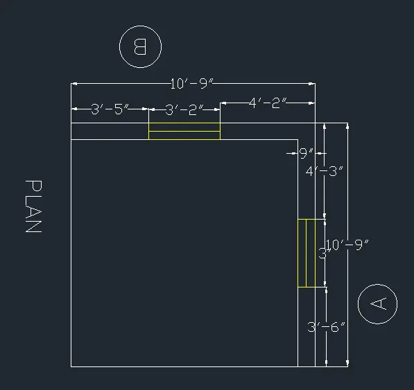
Then Top view is selected in VIEW cube
Now create a region in the wall area by command "BO" for boundary.
Go to shaded view to see the boundary
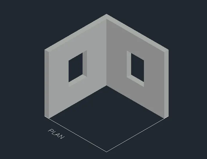
Now extrude the region , givng a height of 10'. Command "EXTRUDE"
Draw a rectangle over the window portion.
Extrude it to 3' ie to sill level
Similarly create a rectangle at the top
Then extrude it downwards at 3' distance by EXTRUDE command
Then view option is selected in Realistic
Then for the window portion
Create rectangle with length of 4' and 3'2" width
Then create inner two rectangle with 3" and 4" spacing
Then extrude the rectangles by 3" with EXTRUDE command
From layer option select layer for window with different color
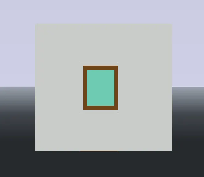
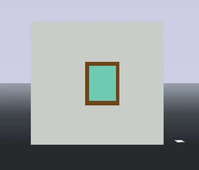
Then place the created rectangles in elevation A and elevaton B
ELEVATION A
ELEVATION B
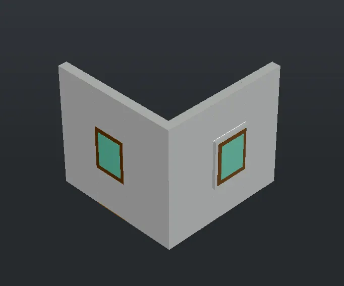
Result
Thus the 3D model of building plan and isometric view is created and window is also created
2.
Aim
To create the 3D View of the Building Façade as given in the plan and elevation
Introduction
Create the 3D View of the Building Façade as given in the plan and elevation
Window should be drawn with the help of details of window given
Procedure
AutoCAD is opened with Imperial setting as default.
In units of measurement Architectural is selected.
Precision is set to 0'-0.0".
Top view is selected in VIEW cube and plan is created with LINE, TRIM, and OFFSET commands as per dimensions
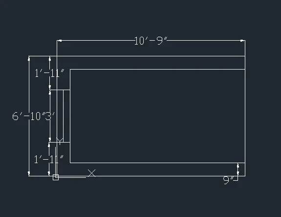
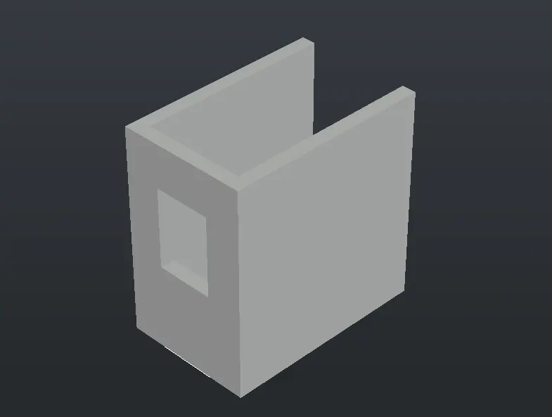
In the View cube Home icon is clicked and the BOUNDARY command and region option is selected to make walls into regions.
As the sill level height is given as 4'6" and window height as 4' ,and top height from the window is 2'5"
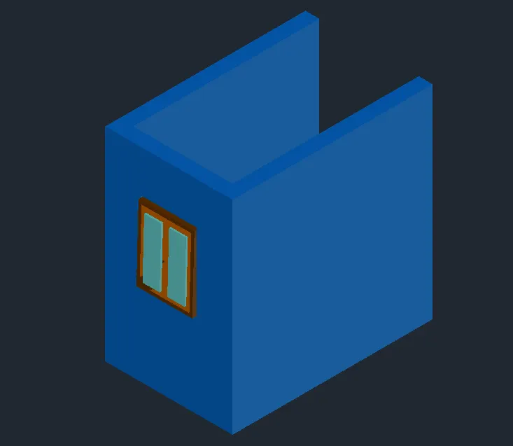
With EXTRUDE command extrude the created region giving a height of 10'-11 for wall
Create a rectangle at the bottom of the window position.
Extrude it to a height of 4'6".
Similarly create a rectangle at the top and extrude 2'-5" downwards
Create the window elevation of the plan in 2D top view
Create window with given dimensions
Then group the window elements.
Then extrude it by 3"
Place the elevation in front of the 3D image.
With 3DRotate command rotate the elevation by 270 degree
Place it in parallel to the face of building
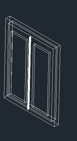
With layer properties create new layer and select colors for window
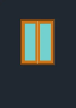
Move this window and place on the gap in 3d wall
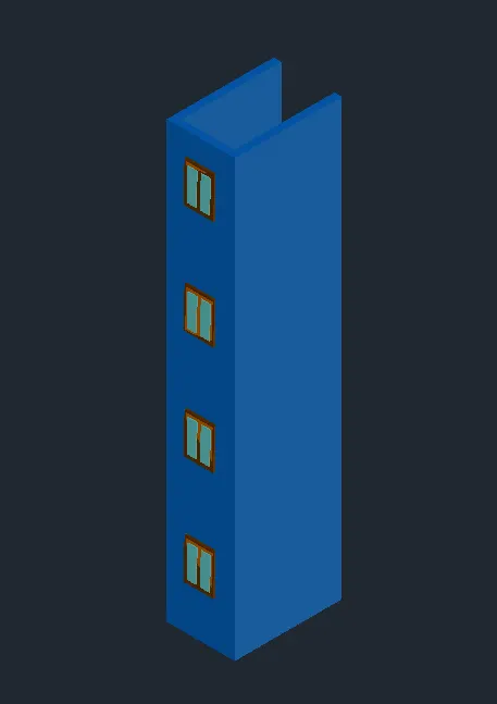
Copy all the object
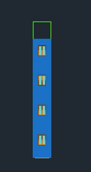
And place it on the top of the wall and create 4 floors similarly
In top view
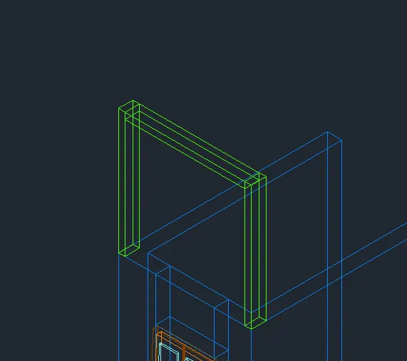
Draw a rectangle with dimensions 9" x 4".
Extrude it by 6'5"
Copy that column and place it on other end
Then create perpendicular at the top of both columns by
Creating rectangle at top and extrude downwards by 4"
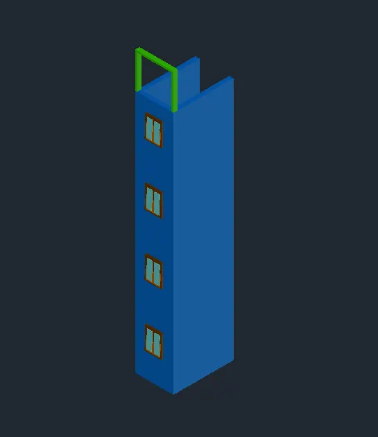
Then change the view type to realistic
Result
Thus the 3D View of the Building Façade as given in the plan and elevation is created
3.
Aim
Tp create the ismoteric 3d view of a stair with railing as shown in the plan and elevation.
Introduction
Create the ismoteric 3d view of a stair with railing as shown in the plan and elevation.
Size of balustrades and hand rails should be assumed
Procedure
AutoCAD is opened with Imperial setting as default.
In units of measurement Architectural is selected.
Precision is set to 0'-0.0"
With tread as 1' and riser as 6" , draw the steps in the top view 2d wireframe.
Landing is 3' and the waist slab is 6" thickness
And dimensions are marked
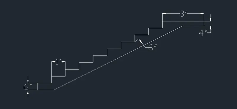
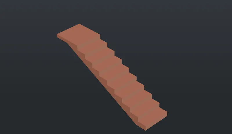
Join all these and create a region
With 3d orbit place the section in such a way that it is visible.
Extrude 3' towards the side for width of the stair
With 3d rotate -select x axis and give the value 90 degree.
For creating balustrades
Place the UCS on the tread and ceate a circle of diameter 2" at corner
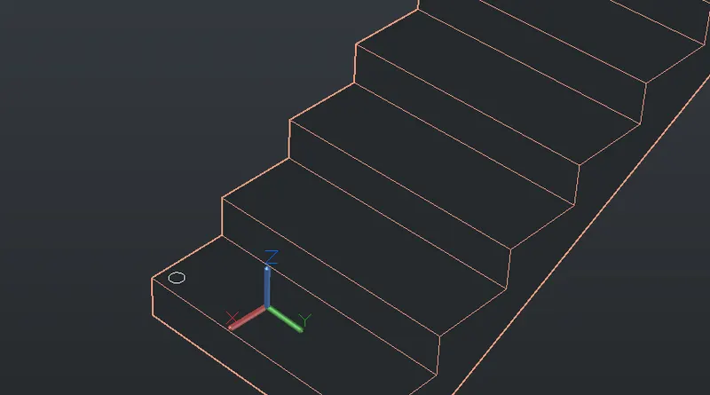
Then extrude the circle at 3'2" by EXTRUDE command
Now copy it and place it in all tread as shown in fig
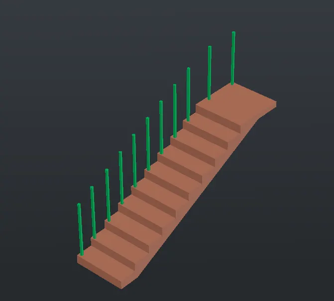
For creating handrails
At top of the staircase, create 2" circle at z-axis in top balustrade
Then, create a polyline joining the balustrades by "3DPOLY" command
Now using SWEEP command, sweep it by selecting the circle click ENTER and then select the polyline
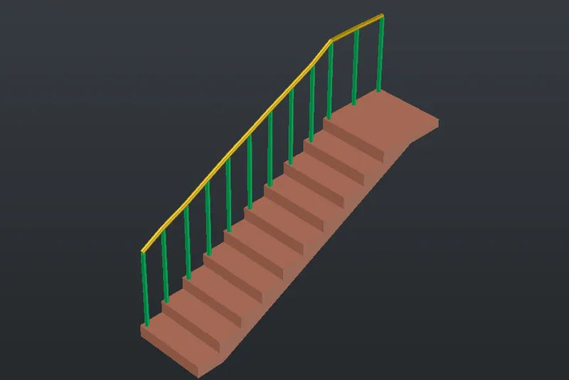
Result
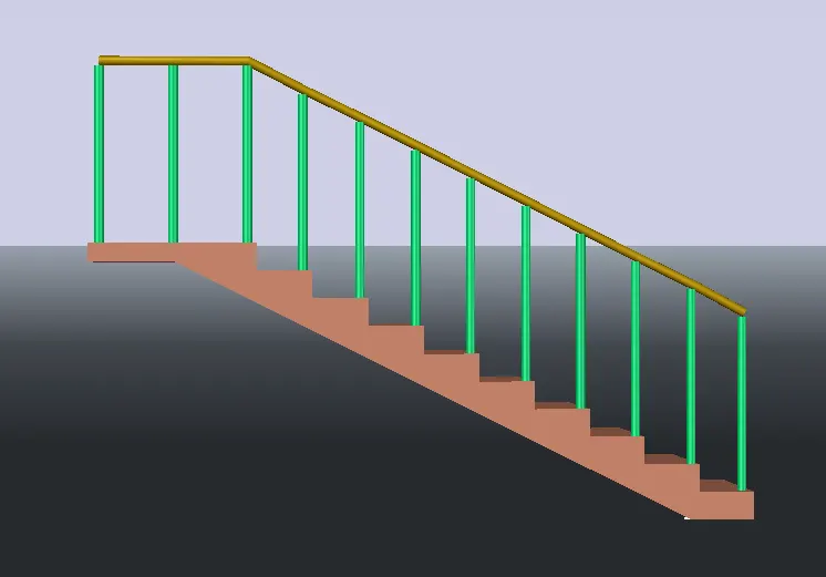
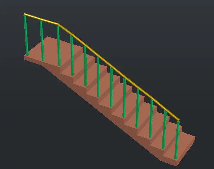
The ismoteric 3d view of a stair with balustrades and hand rails are created
4.
Aim
To create the 3D view of a Wall with spread footing
Introduction
Create the 3D view of a Wall with spread footing .
Create the Door opening only.
Assume the size of the parapet and the coping. See the plans and elevation for the details. Also, create a rendered view of
the model with materials
Procedure
AutoCAD is opened with Imperial setting as default.
In units of measurement millimeters is selected.
Precision is set to 0
With line command draw a vertical line of 7500mm and 230mm width
Draw a centre line in wall and offset 150mm on both sides so that the total width is 300mm
From the 300mm line offset 25mm on both sides then the total width becomes 350mm.
From the centre again offset 300mm on both sides , the total width is 600mm
Extend the horizontal line at both ends
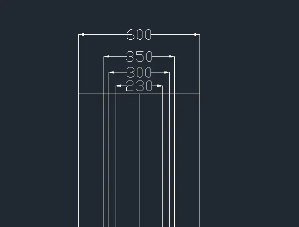
Offset 3300mmfrom both the sides for the door opening of 900mm
Create door in the opening by arc and line.
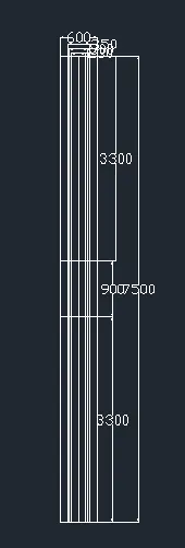
Hatch the wall , foundation with different hatches.
ANS 132 for wall , Solid for footing , AR-CONC for bottom
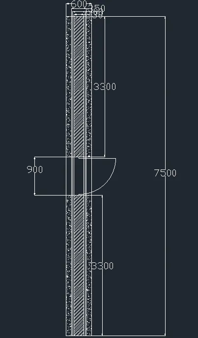
Click home icon at right corner to make into 3d
Create a rectangle profile on top of the plan
Create region by REGION command
Extrude it by 300mm.
Then draw the next rectangle
Extrude it by 700mm
The next rectangle is drawn inside
Extrude it by 1100mm from bottom
Last rectangle inside is drawn
Then extrude it by 1650mm from ground
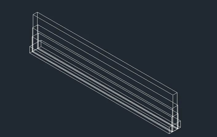
Then create rectangle at top
And extrude it by 50mm
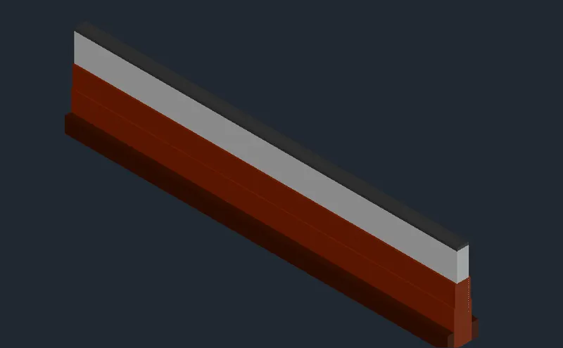
Then create rectangle at top, at both ends with dimension of 230mm x 3300mm
Now extrude it by 3300mm
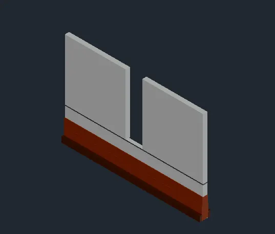
Create a rectangle profile at top at gap between wall
Move it downwards 1050mm by MOVE command
Extrude it down at a height of 150mm
Again create rectangle at gap
Extrude it down by 1050
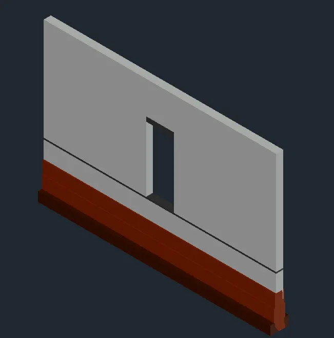
Keep the ucs on the side face.
Draw a horizontal line from bottom of the lintel , then a vertical line 50mm to top.
On the other side draw a vertical line of 100mm upwards,then join these two points of 50 and 100.
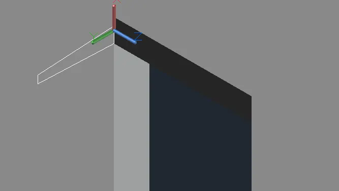
Make it as a region by REGION command
Extrude right side by 900mm
Now create rectangle at top and extrude it by 150mm top
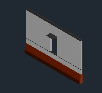
Create a rectangle of 7500mm and 150mm on top of the 3d model
Extrude it by 750mm at top
Then draw line at left edge of wall at top
Then draw a small rectangle of 60mmx40mm right corner by placing UCS icon and cganging its face
Now using SWEEP command sweep it by selecting rectangle and then the line
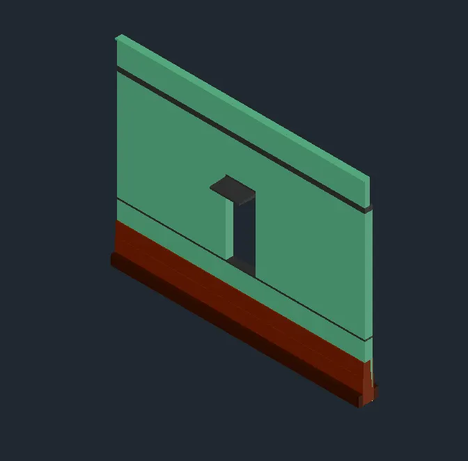
For rendered view
Render the model by RR command
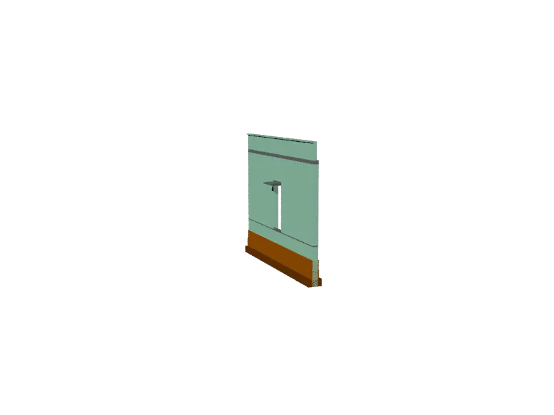
Result
The 3d model of wall with spread footing and opening is created