Creating 3D Isometric view of various structural elements in AutoCAD
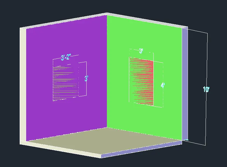
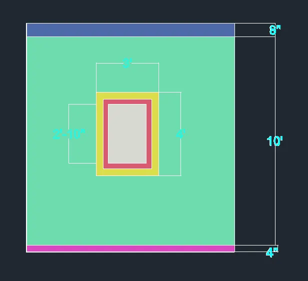
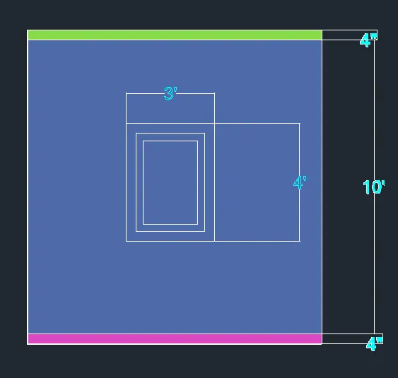
AIM:To creeat a 3D isometric view of the building with plan and elevation by using Autocad 3D modelling.
PROCEDURE:
- First open the Autocad and click on settings below and in that select 3D modelling.
- After selecting the 3D modeling set the units and limits as per the drawing requirements.
- After that go to views and select top view and draw the drawing in 2d modeling.
- After draw in 2d modeling go to conceptual view and exturde the solid objects to required height and then by using the solidedit command edit the solid object.
- The colour are given to the faces of the solid object by using the solidedit command.
- Use the 3dorbit command to view the solid object in 360 degrees.
- The solid object edges colours are given by using the solid edit command in the edge and click on colour.
- All the lines in the above drawing are drawn by using line command in the below command section.
- Trim command is used to remove unwanted objects in the above drawing.
- Dim command is used to give all the dimensions in the drawing.
- Dimensions are given to the 3d solid objects by using UCS command.
- UCS command is used to give dimensions in the z-axis direction.
- Offset command is used to creat another object with the same dimensions of the objects.
- rec command is used to draw the walls and windows.
COMMANDS USED IN THE ABOVE DRAWINGS ARE:
- line command
- extrude ommand
- solidedit command
- 3dorbit command
- trim command
- dim command
- ucs command
- offset command
- rec command
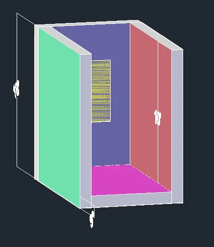
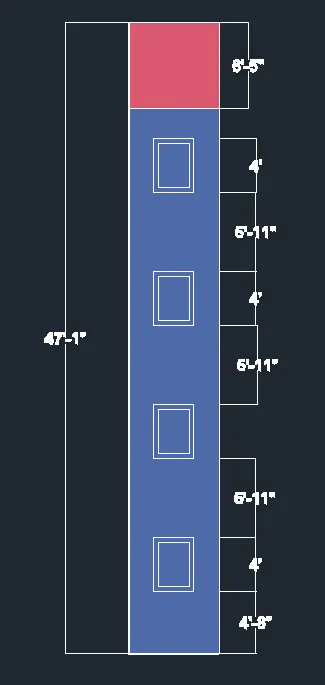
AIM:To creeat a 3D isometric view of the building with plan and elevation by using Autocad 3D modelling.
PROCEDURE:
- First open the Autocad and click on settings below and in that select 3D modelling.
- After selecting the 3D modeling set the units and limits as per the drawing requirements.
- After that go to views and select top view and draw the drawing in 2d modeling.
- After draw in 2d modeling go to conceptual view and exturde the solid objects to required height and then by using the solidedit command edit the solid object.
- The colour are given to the faces of the solid object by using the solidedit command.
- Use the 3dorbit command to view the solid object in 360 degrees.
- The solid object edges colours are given by using the solid edit command in the edge and click on colour.
- All the lines in the above drawing are drawn by using line command in the below command section.
- Trim command is used to remove unwanted objects in the above drawing.
- Dim command is used to give all the dimensions in the drawing.
- Dimensions are given to the 3d solid objects by using UCS command.
- UCS command is used to give dimensions in the z-axis direction.
- Offset command is used to creat another object with the same dimensions of the objects.
- rec command is used to draw the walls and windows.
COMMANDS USED IN THE ABOVE DRAWINGS ARE:
- line command
- extrude ommand
- solidedit command
- 3dorbit command
- trim command
- dim command
- ucs command
- offset command
- rec command
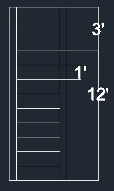
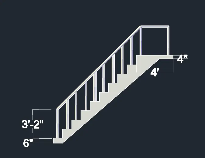
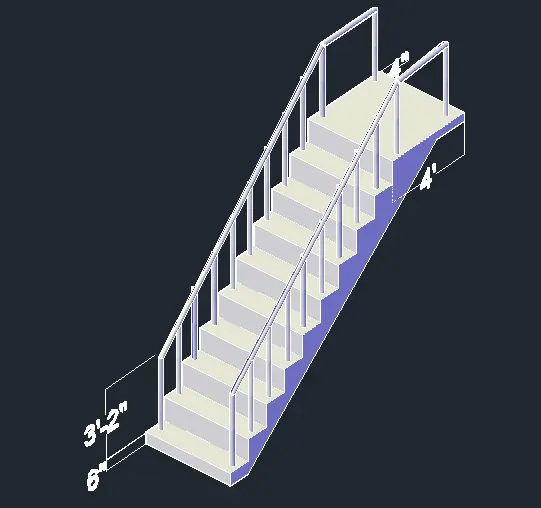
AIM:To creeat a 3D isometric view of a stair with railing by using Autocad 3D modelling.
PROCEDURE:
- First open the Autocad and click on settings below and in that select 3D modelling.
- After selecting the 3D modeling set the units and limits as per the drawing requirements.
- After that go to views and select top view and draw the drawing in 2d modeling.
- After draw in 2d modeling go to conceptual view and exturde the solid objects to required height and then by using the solidedit command edit the solid object.
- The colour are given to the faces of the solid object by using the solidedit command.
- Use the 3dorbit command to view the solid object in 360 degrees.
- The solid object edges colours are given by using the solid edit command in the edge and click on colour.
- The balustrades and hand rails are created by the cylinder command and sweep command to draw the path.
- All the lines in the above drawing are drawn by using line command in the below command section.
- Trim command is used to remove unwanted objects in the above drawing.
- Dim command is used to give all the dimensions in the drawing.
- Dimensions are given to the 3d solid objects by using UCS command.
- UCS command is used to give dimensions in the z-axis direction.
- Offset command is used to creat another object with the same dimensions of the objects.
- rec command is used to draw the walls and windows.
COMMANDS USED IN THE ABOVE DRAWINGS ARE:
- line command
- extrude ommand
- solidedit command
- 3dorbit command
- trim command
- dim command
- ucs command
- offset command
- rec command
- cylinder command
- sweep command
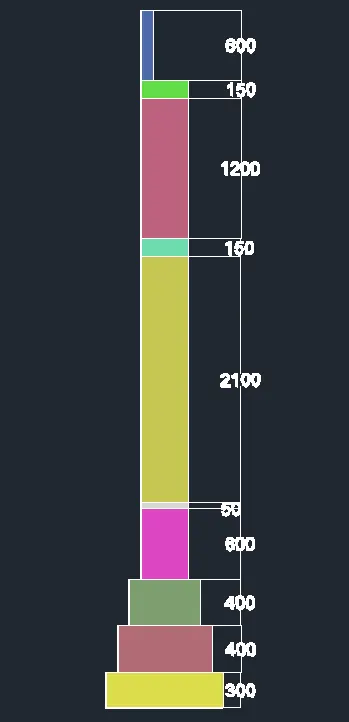
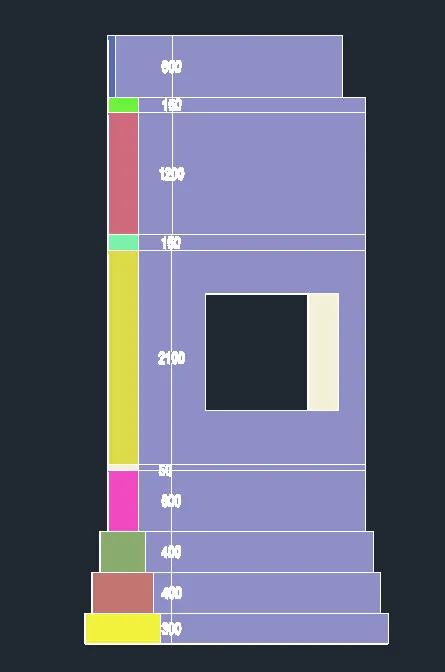
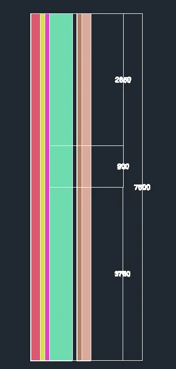
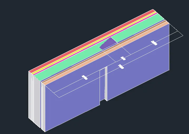
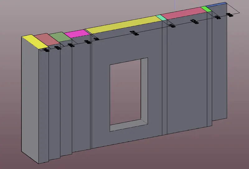
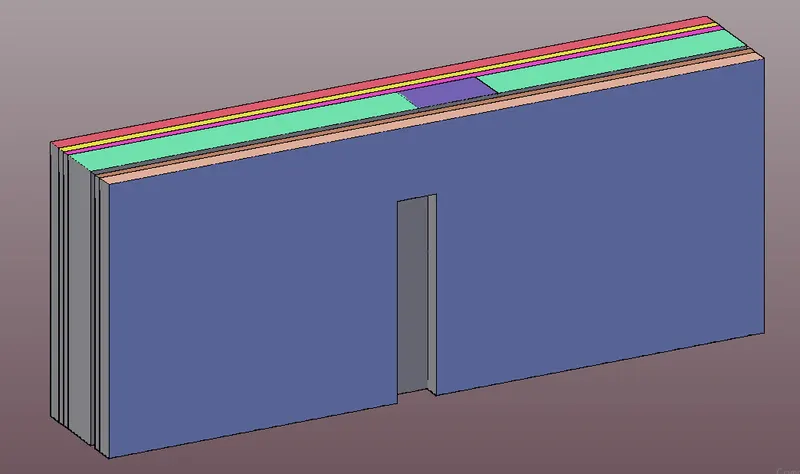
AIM:To creeat a 3D isometric view of a wall with spreading footing by using Autocad 3D modelling.
PROCEDURE:
- First open the Autocad and click on settings below and in that select 3D modelling.
- After selecting the 3D modeling set the units and limits as per the drawing requirements.
- After that go to views and select top view and draw the drawing in 2d modeling.
- After draw in 2d modeling go to conceptual view and exturde the solid objects to required height and then by using the solidedit command edit the solid object.
- The colour are given to the faces of the solid object by using the solidedit command.
- Use the 3dorbit command to view the solid object in 360 degrees.
- The solid object edges colours are given by using the solid edit command in the edge and click on colour.
- The subrtact command is used to remove one solid object from the another object.
- Also use render command to render the solid object image by giving some properties of the render.
- All the lines in the above drawing are drawn by using line command in the below command section.
- Trim command is used to remove unwanted objects in the above drawing.
- Dim command is used to give all the dimensions in the drawing.
- Dimensions are given to the 3d solid objects by using UCS command.
- UCS command is used to give dimensions in the z-axis direction.
- Offset command is used to creat another object with the same dimensions of the objects.
- rec command is used to draw the walls and windows.
COMMANDS USED IN THE ABOVE DRAWINGS ARE:
- line command
- extrude ommand
- solidedit command
- 3dorbit command
- trim command
- dim command
- ucs command
- offset command
- rec command
- substract command
- render command.