Creating 3D Isometric view of various structural elements in AutoCAD
- PROBLEM NO : 1
- AIM :
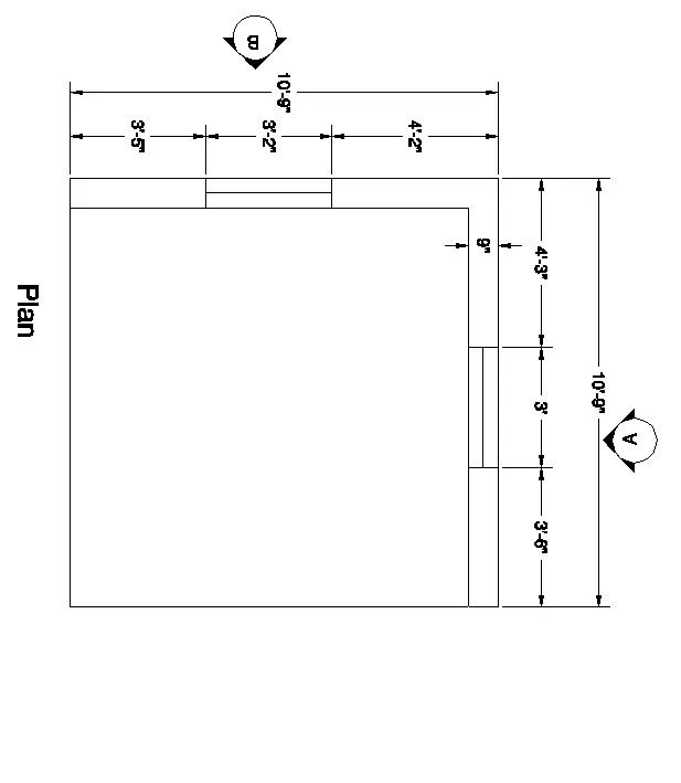
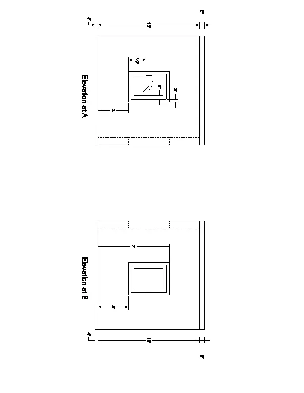
- PROCEDURE USED :
- start the autocad software in laptop
- command : QNEW
- select the imperial
- click on advance setup
- set unit : engineering precision :0',0"
- set angle : decimal degree , precision : 0
- click on next butten
- set angle measure : east
- angle direction : counter clockwise
- press : next
- set area : 40'x40'
- press : enter
- keep ortho < ON
- grid mode < OFF
- command : UN (for units )
- select the scale as engineering precision : 0'-0"
- select the scale as inches
- press : enter
- command : REC (for rectangle )
- select the start point by clicking anywhere
- click on dimension
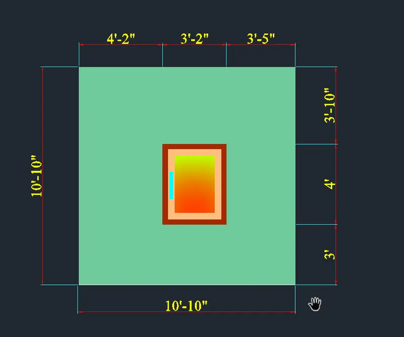
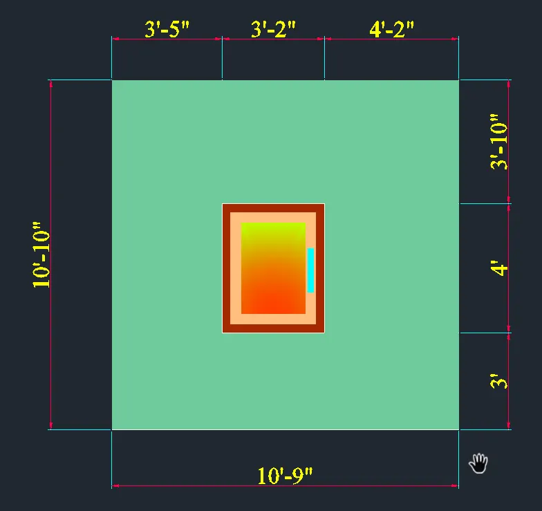
- length : 10'-9"
- width : 10'-9"
- press : enter
- command : O (for ofset )
- select the object
- distance : 9"
- press : enter
- command : X (for explode )
- select the object
- press : enter
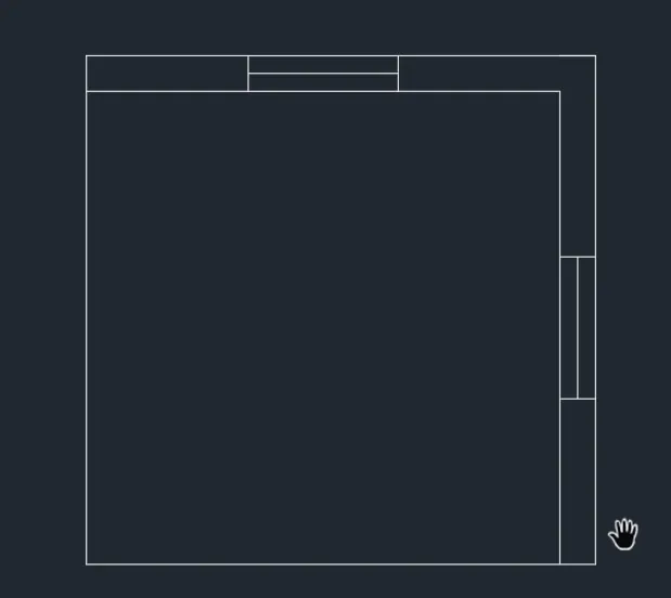
- command : TR (for triam )
- triam the extra lines
- draw the window by using lie and ofset command
- press : enter
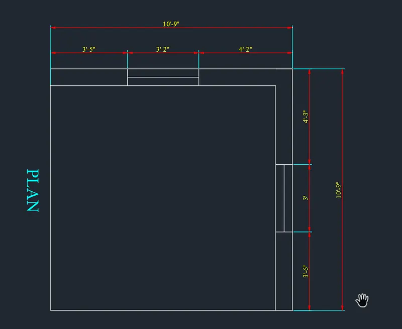
- command : DIMLIN (for dimension )
- give the dimension
- press : enter
- commad : MTEXT (for text )
- write the text
- press : enter
- go to the workspace
- slect the workspace as 3DModelling
- slect the visual style as 2D wireframe
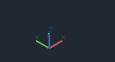
- command :UCS
- set the ucs direction as shown below
- command : BO (for boundary )
- click on pick a point
- select the internal portion of a will
- press : enter
- command : EXT (for extodue )
- give the height of extodu as 10'-10"
- press : enter
- command : SHADED
- press : enter

- go to the 2D wireframe
- command : REC (for rectangle )
- selet the start point
- and draw the rectangle for window
- command : BO (for boundary )
- slect the pick a point
- and give the region to the rectangle
- command : EXT (for extrude )
- select the object
- give the extude hight is 10'-10"
- precc enter
- command : REC (for rectangle )
- select the start point
- click on dimension
- length :3'
- width :4"
- press : enetr
- command : MOVE
- select the rectangle
- slect the base point
- specfy next point of move as @0,0,3"
- press : enter
- command : UNION
- select the solid object
- press : enter
- then ,
- command :SUBSTRACT
- select the object
- press : enter
- then select the object which can be substract
- press : enter
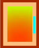
- command : H (for hatch )
- give the hatch to the window as shown in fig
- same way draw the another side of window
- move and rectangle command is used to draw the another side of window
- command : USC
- selct the proper direction
- and give the dimension to the solid object
- slect the visual style as shaded
- select the object
- go to the properties
- and change the colour of object
- as shown in fig
- then ,
- go to the REBBIN
- click on VIEW
- create a new view
- as shown in fig
- in this way 3D object is ready
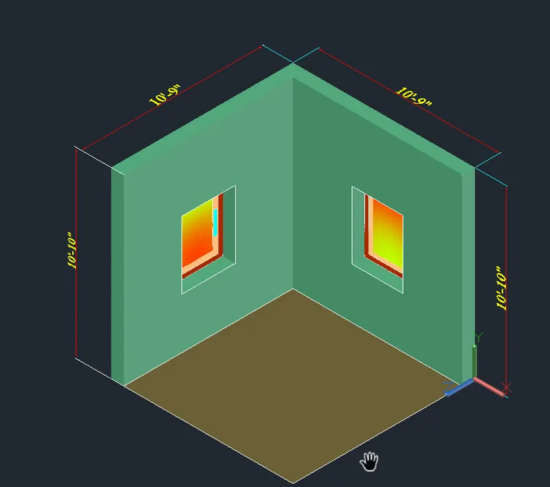
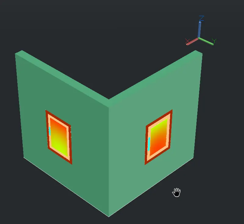
- RESULTS
- VIEW A :
- VIEW B :
- ELEVATION
- ELEVATION
- PROBLEM NO : 2
- AIM :
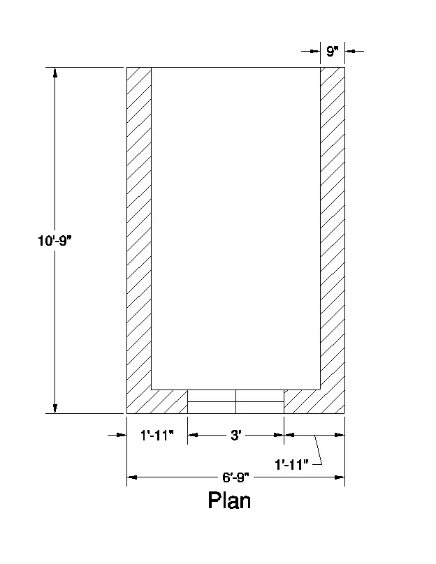
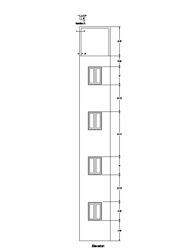
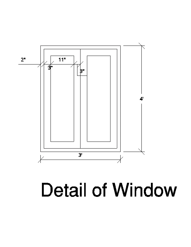
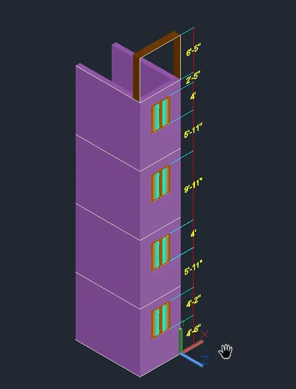
- Create the 3D View of the Building Façade as given in the plan and elevation. Also, see the detail of the window.
- PROCEDURE :
- start the autocad software in laptop
- command : QNEW
- select the imperial
- click on advance setup
- set unit : engineering precision :0',0"
- set angle : decimal degree , precision : 0
- click on next butten
- set angle measure : east
- angle direction : counter clockwise
- press : next
- set area : 40'x40'
- press : enter
- keep ortho < ON
- grid mode < OFF
- command : UN (for units )
- select the scale as engineering precision : 0'-0"
- select the scale as inches
- press : enter
- command : REC (for rectangle )
- select the start point
- click on dimension
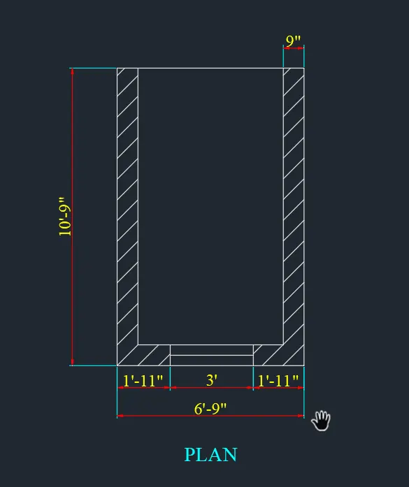
- length : 6'-9"
- width : 10'-9"
- press : enter
- command " X (for explode )
- select the object
- press : enter
- command : O (for ofset )
- give the ofset distance as 9"
- press : enter
- by using ofset command and line cimmand draw the window section
- command : DIMLIN (for dimension )
- give the dimension to the section
- press : enter
- cpmmand : MTEXT (for text )
- give the text to the plan
- press : enter
- go to the work space
- then switching iT as 3D Modelling
- then select the visual style as 2D wirefrae
- command : 3DO (foe orbit )
- move the cursur as per requrimennt
- command : UCS
- ucs direction as shown below
- command : BO(for boundary )
- slect the pick a point
- click on internal walll
- press : enter
- command : SHADED
- press : enter
- command : EXT (for extrude )
- select the object
- then give the extrude height as 9'-11"
- press : enter
- command : REC (for rectangle )
- select the corner point of window
- press : enter
- command : BO (for boundary )
- select the pick a point
- press : enter
- command : EXT (for extrude )
- select the object
- give the height is 3'
- press : enter
- usend the UNION and SUBSTRACT command to draw the full window portion
- then command :REC (for rectangle )
- select the start point
- click on DIMENSION
- length : 3'
- width : 4'
- press : enter
- command : O (for ofset )
- distance :2"
- select the rectangle and give the ofst at a distance if 2"
- by using divide command divide the inner rectangle
- command rectangle
- and draw the rectangle in between inner rectangle having size 3" x11"
- press : enter
- command " MI (for mirror )
- slect the orectangle and mirror it
- press : enter
- command : H (for hatch )
- and give the hatch to the window shown in below
- command : MOVE
- slect the object
- and placed it as per recquriment
- press : enter
- then select the object
- go to the properties
- and give the colour to the object as shown in below
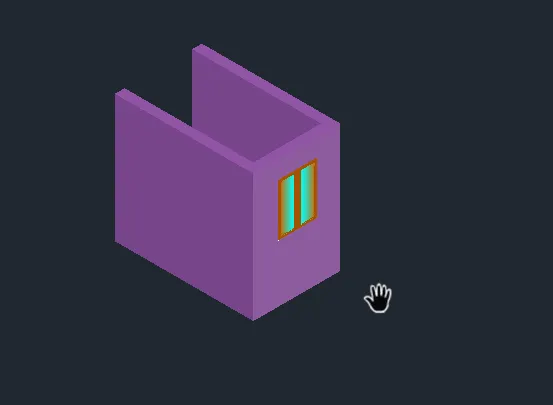
- command : 3DCOPY
- select the object
- click on MULTIPLE
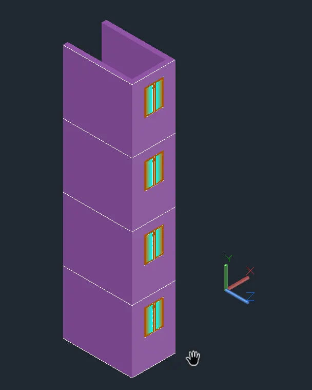
- and copy it as shown below
- used usc and line and extrude command to draw the upper portion of building
- press : enter
- command :UCS
- give the requried dimension
- command : DIMLIN (for dimension )
- give the dimension
- then usend DIMCONTINUE command for other dimension
- press :enter
- 3D object is created
- click on VIEW
- create a new view as shown in results
- press : enter
- RESULTS :
- ELEVATION :
- PROBLEM NO : 3
- AIM :
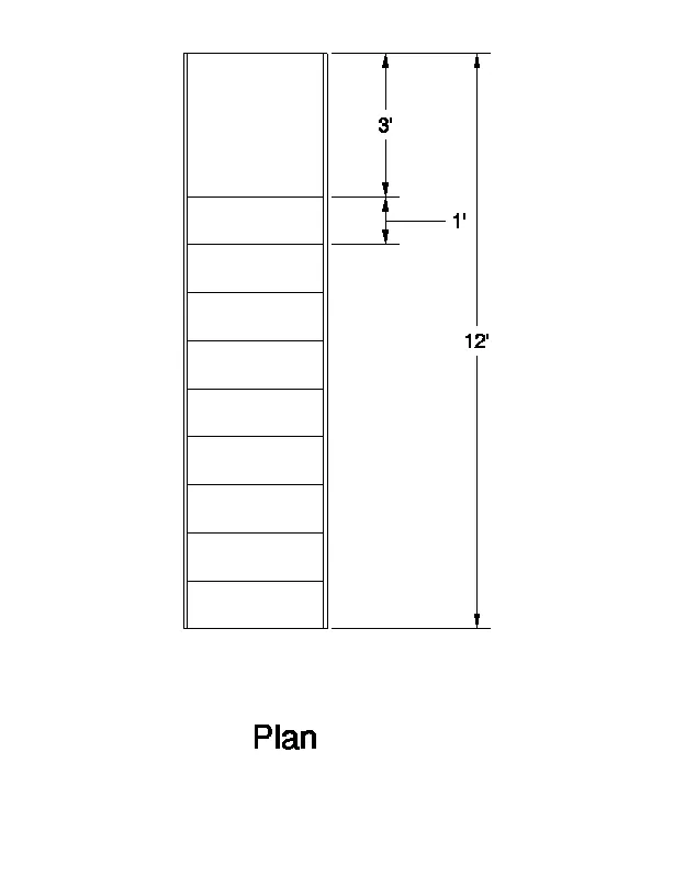
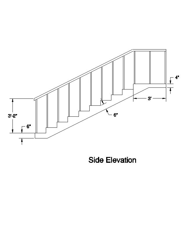
- Create the ismoteric 3d view of a stair with railing as shown in the plan and elevation. Assume the size of the balustrades and the hand rails.
- PROCEDURE :
- start the autocad software in laptop
- command : QNEW
- select the imperial
- click on advance setup
- set unit : engineering precision :0',0"
- set angle : decimal degree , precision : 0
- click on next butten
- set angle measure : east
- angle direction : counter clockwise
- press : next
- set area : 40'x40'
- press : enter
- keep ortho < ON
- grid mode < OFF
- command : UN (for units )
- select the scale as engineering precision : 0'-0"
- select the scale as inches
- press : enter
- go to the workspace
- and switch it as 3D Modelling
- select the visual style as a 2D Wireframe
- command : 3Dorbit
- then selct the ucs directaion as shown in fig
-
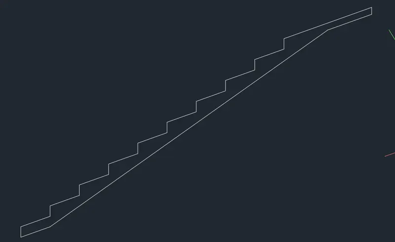
- command : L (for line )
- slect the start point anywhere
- specify next point as @ 0,0,6" enter
- specify next point as @1',0,0 enter
- specify next point @0,0,6" enter
- specify next point @1',0,0 enter
- specify next point @0,0,6" enter
- specify next point @1',0,0 enter
- specify next point @0,0,6" enter
- specify next point @1',0,0, enter
- specify next point @0,0,6" enter
- specify next point @1',0,0 enter
- specify next point @0,0,6" enter
- specify next point @1',0,0 enter
- specify next point @0,0,6" enter
- specify next point @1',0,0 enter
- specify next point @0,0,6" enter
- specify next point @1',0,0 enter
- specify next point @0,0,6" enter
- specify next pont @1',0,0 enter
- specify next point @0,0,6" enter
- specify next point @3',0,0 enter
- specify next point @0,0,-4 enter
- command : O (for ofset )
- distance : 6"
- for weist slab
- press : enter
- command : BO (for boundary )
- click on Pick a point
- slect the point
- press : enter
- command : SHADED
- PRESS :ENTER
- Command : EXT (for extrude )
- select the staircase and give the length of extrude is 3'
- press : enter
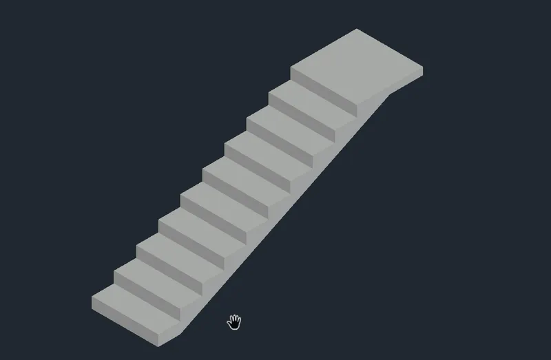
- command : C (for circle )
- for railling
- select the start point
- click on DIAMETER
- give diameter as 4"
- press enter
- command : EXT (for extrude )
- select the circle
- give the height as 3'-2"
- press : enter
- command : COPY
- selct the object
- give the base point
- click on MULTIPLE
- copy it
- command : 3DPOLYLINE
- DrAW the line for horizontal handgrill
- command : SWEEP
- And draw the horizontal handgrill
- then select the object
- go to the properties
- give the colour to the object as shown below
- click on VIEW
- create a new view as shown in below
- command DIMLIN and UCS command used for the dimension
- press : enter
- in this way 3D object is created
- RESULTS :
- VIEWS A :
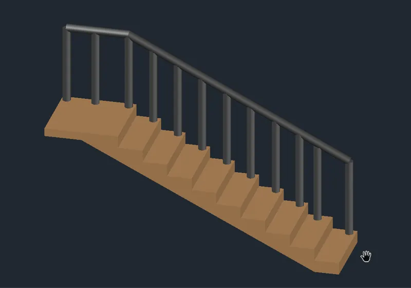
- VIEW B :
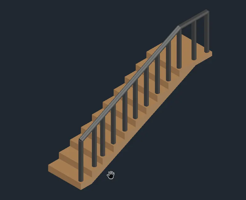
- VIEW C:
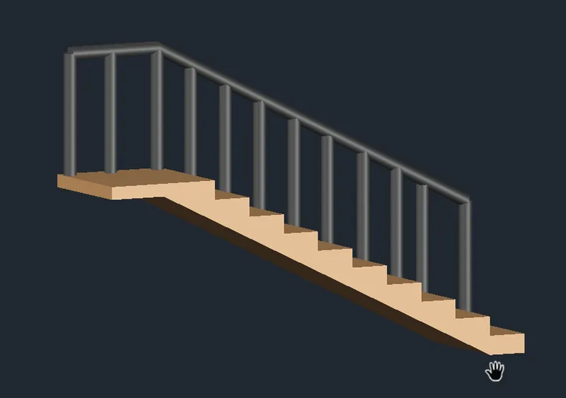
- PROBLEM NO : 4
- AIM :
-
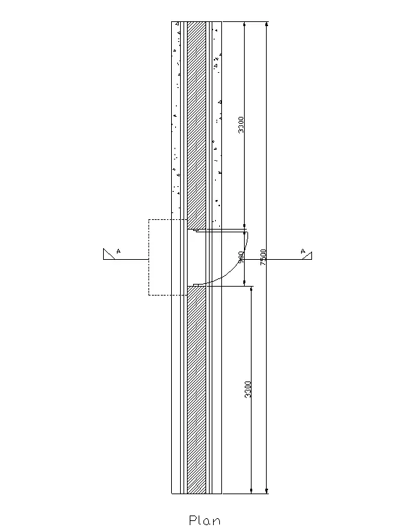
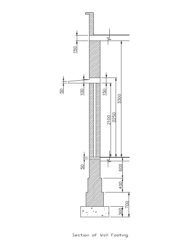
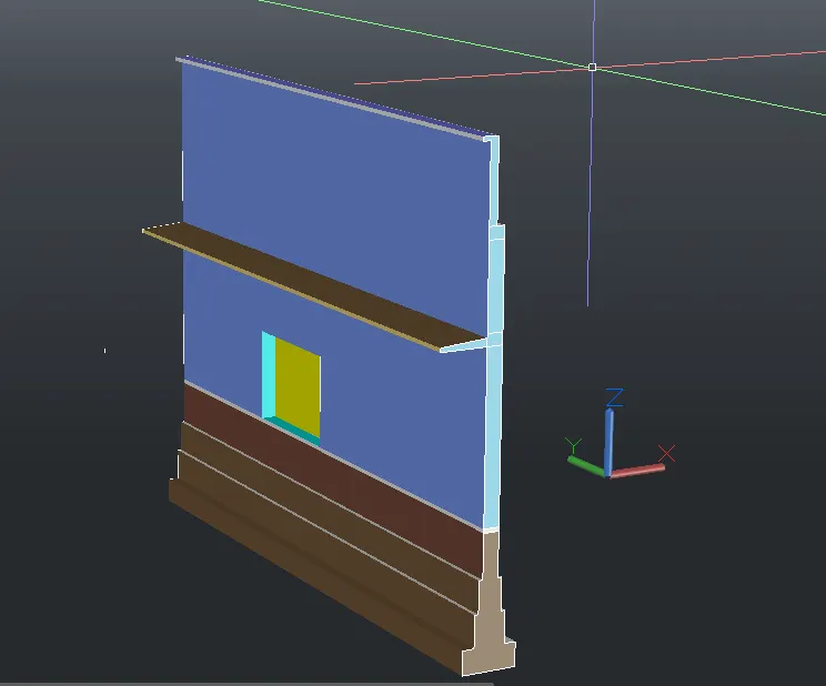
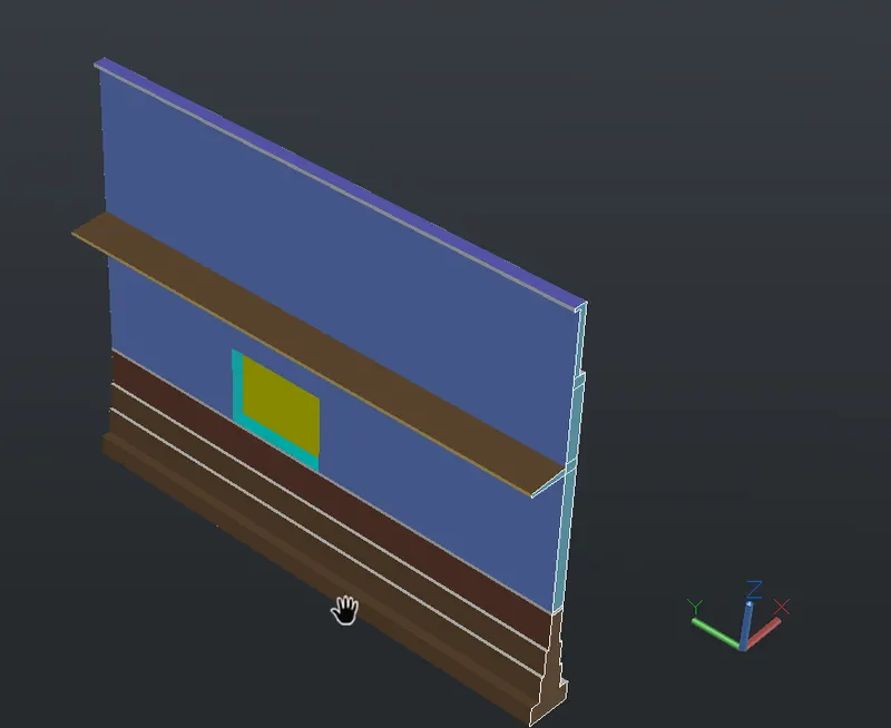
Create the 3D view of a Wall with spread footing . Create the Door opening only. Assume the size of the parpaet and the coping. See the plans and elevation for the details. Also, create a rendered view of the model with materials as of your choice.\
- PROCEDURE :
- start the autocad software in laptop
- command : QNEW
- select the imperial
- click on advance setup
- set unit : decimal precision :0
- set angle : decimal degree , precision : 0
- click on next butten
- set angle measure : east
- angle direction : counter clockwise
- press : next
- set area : 12 mx 12m
- press : enter
- keep ortho < ON
- grid mode < OFF
- command : UN (for units )
- select the scale as decimal precision : 0
- select the scale as mm
- press : enter
- command : REC (for rectangle )
- select the start point anywhere
- click on dimension
- length : 700
- width : 300
- press : enter
- command : X (for expode )
- select the object
- press : enter
- by the same procedure draw the all rectangle by using RECTANGLE AND EXPLODE command
- used LINE and OFSET command for other work
- press : enter
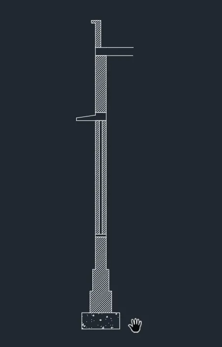
- command : H (for hatch )
- select the proper hatch patern
- and give the hatch
- press : enter
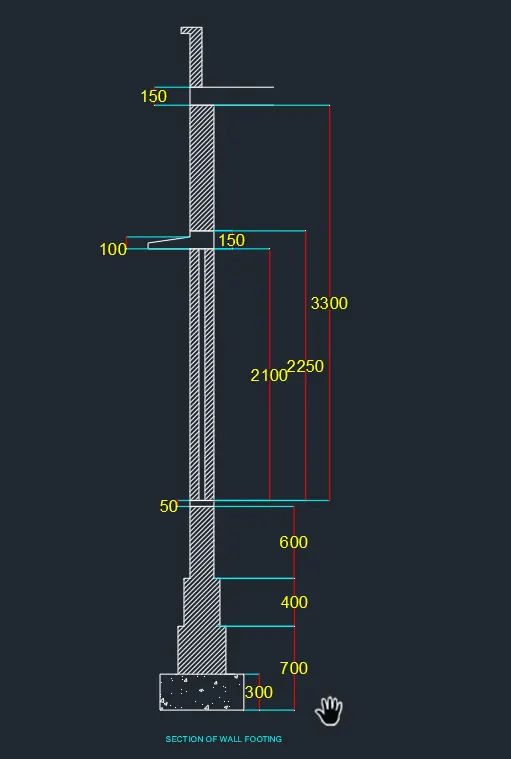
- command DIMLIN (for dimension )
- give the all dimension
- press : enter
- command : MTEXT (for text )
- write the text over plan
- go to the workspace
- then switch the 3D WORKSPACE
- slect the visual style as 2D wireframe
- command : 3DORBIT
- command : UCS
- and ucs direction shown in below
- command : BO (for boundary )
- click on pick a point
- select the object
- press : enter
- command : 3DROTARE
- rotare it as xz plan
- press : enter
- command : EXT (for extrude )
- select the object
- give the extrude heigth as 7000
- press : enter
- then draw the door portion by using UNION AND SUBSTRACT COMMAND
- then select the solid object
- go to the properties
- and give the recquried portion
- then by using UCS commnd and DIMLIN and DIMCONTINUE command
- give the dimension
- press : enter
- in this way 3D drawing is ready
- go to the VIEW option
- click on NEW VIEW
- and create a view as shown in below
- RESULTS :
- VIEW A
- VIEW B :
- COMMAND USED IN PROJECT :
- START : QNEW
- UNITS : UN
- RECTANGE : REC
- LINE : L
- TRIAM : TR
- EXPLODE : X
- BOUNDARY : BO
- FOR SHADE : SHADED
- HATCH : H
- DIMENSION : DIMLIN
- TEXT : MTEXT
- 3DORBIT
- 3DROTATE
- UCS
- 3DPOLYLINE
- SWEEP
- CIRCLE : C
- EXTRUDE : EXT
- OFSET : O