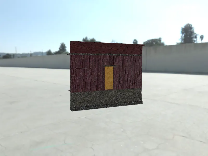
Creating 3D Isometric view of various structural elements in AutoCAD
Introduction: Autocad is a commercial Computer Aided Design(CAD), It is marked and developed as Autodesk. It was first released on december 1982. Autocad derived from a program, which was beganed in 1977 and then released in 1979 called as Interact CAD, and also called in early documents od autocad as microCAD, Auto desk cofounder was Michael Riddle.
The first version of cad was released in december 1982 and was supported on CP/M-80 computers, By march 1986 Aotocad has became most uniquitous cad program worldwide. The file format of autocad was .dwg, and its interchange file format to DXF, have become a standard. Autocad was included support for .dwf, a format developed and promoted by Autodesk, for publishing CAD date. In year 2022 the Autocad 36th major version was released and the 12th consecutive year of Autocad foe Mac.
CAD is a technology which replaces manual drawing with automated process, if you are a drafter, desingner, architect or engineer you have been used 2D or 3D CAD programs i.e., Autocad or Autocad LT software. Autocad helps you in draft construction documentation, explore ideas for design, viaualise concepts through photorealistic renderings and gives how a design performs in real world.
Autocad mailnly used by industries, architects, engineers, city planners, project managers, graphic designers and other professionals.
1. Aim: To create the 3D isometric view for the given plan and elevation in Autocad
Steps:
1.Open new file in Autocad 2023, Type UNITS, use Engineering and take inches
2.Then LIMITS, Limits of lower left corner give (0,0) and limits of upper right corner (100',100')
3. Change the settings to 3D modelling
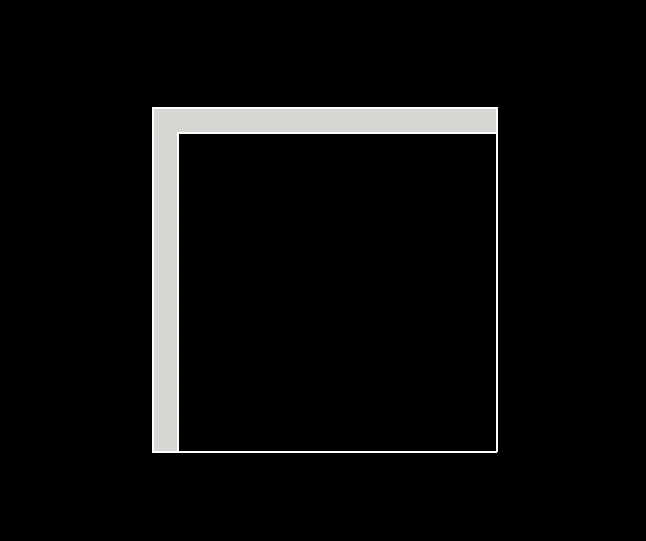
4. Set Top view and draw using line command a square of size 10'9"X10'9"
and Offset the top horizontal and left vertical line 9" in inward direction
and trim at corners
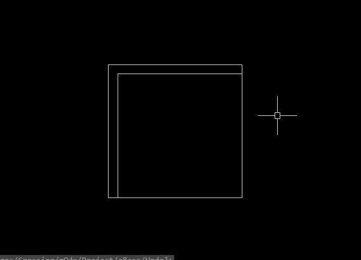
5. Offset the right line in inward by 3'6" and 3'
and offset bottom horizontal line by 3'5" and 3'5" and trim extra lines
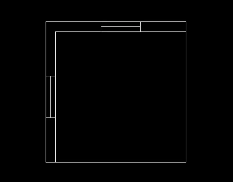
6. Create a layer as dimensions and set current layer and provide dimensions and text
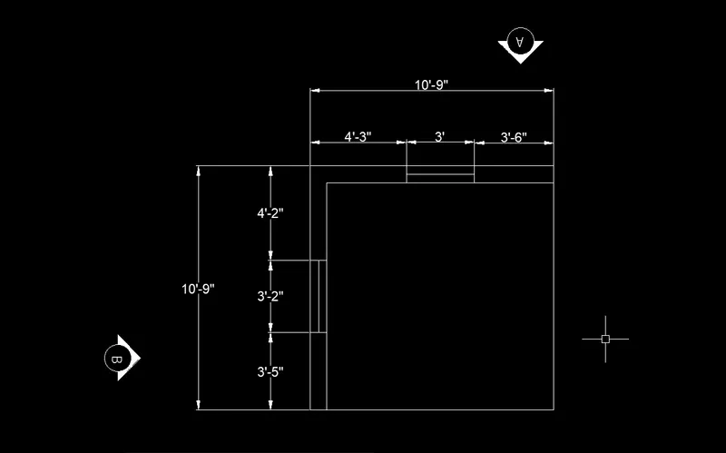
7. Change to SW isometry and hide dimension layer
delete the window lines and using Presspull extrude it by 10'10"
The using Surface extrude, extrude the right vertical and bottom horizontal bu 10'10"
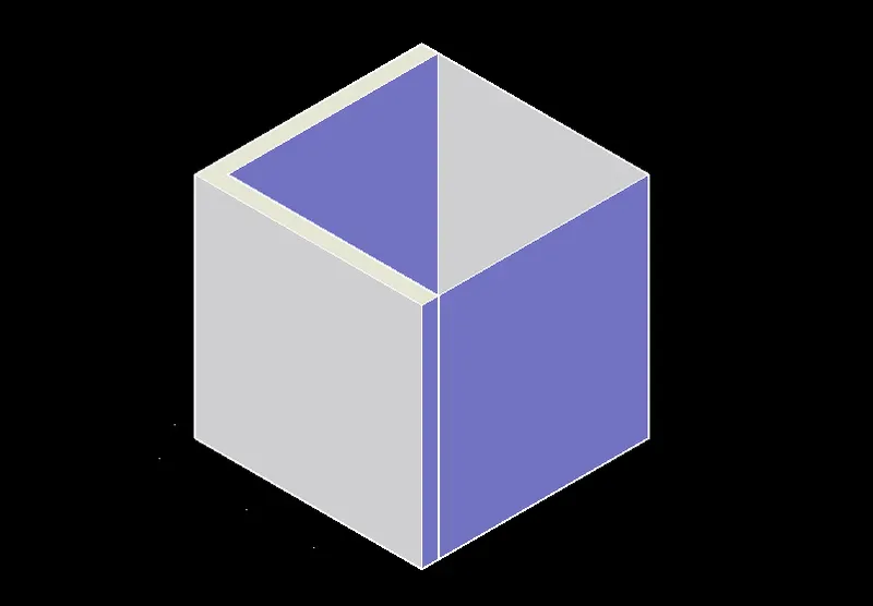
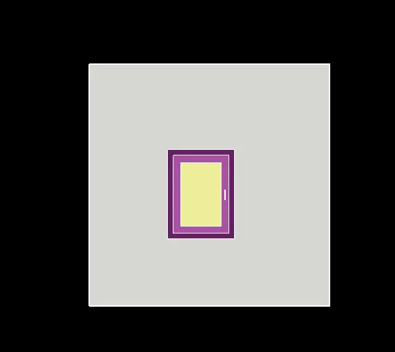
8. To create a window, set view as Left view
create a rectangle of size 3'X4' and Offset inward by 3", 4"
and place the handel at 1'9" from bottom using line command
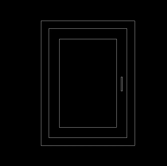
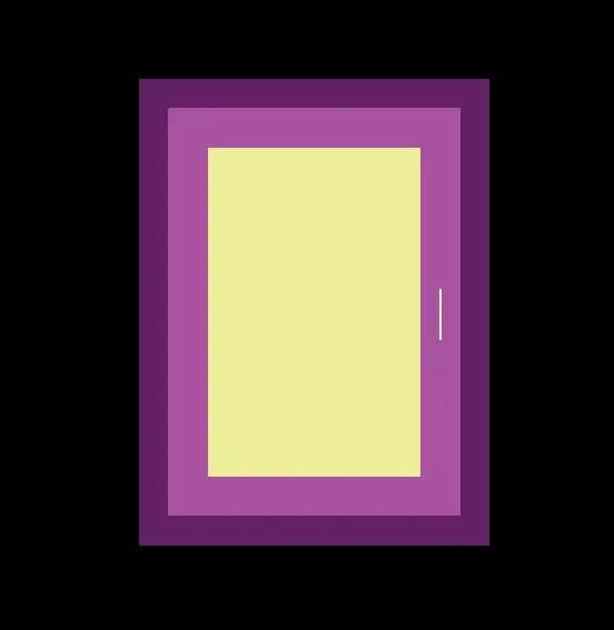
Provide the hatch by different colors and extrude it by 9" in back direction
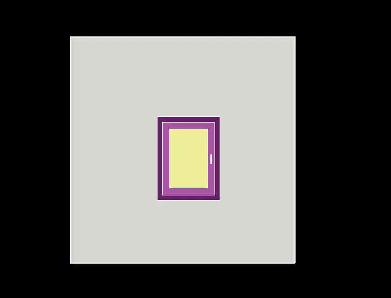
9. Elevation-B:
Keep the UCS at the bottom left corner of elevation B side on change to Left view and set
then draw rectangle by taking coordinates as (4'2",3') and opposite corner as (@3',4')
And using Presspull extrude it by 9" in back direction
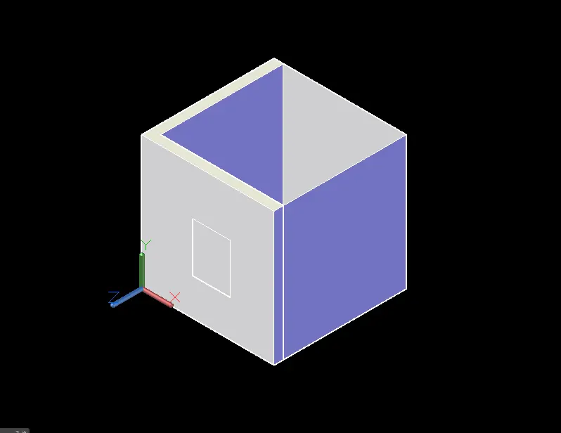
Select subtract command and remove the rectangle part
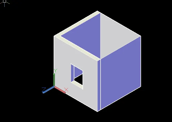
Copy the window and place it in the wall
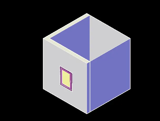
10. Elevation A:
Set view as NW isometric, Keep the UCS at the bottom left corner of elevation B side on change to Left view and set
then draw rectangle by taking coordinates as (3'6",3') and opposite corner as (@3',4')
And using Presspull extrude it by 9" in back direction
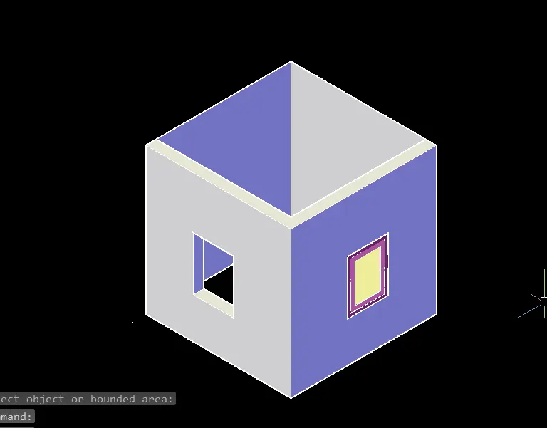
Rotate the created window to fit in elevation A and then copy it and place
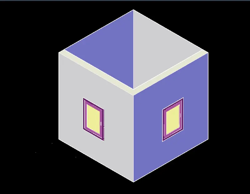
Results:
Plan
Elevation-A
Elevation -B
SW isometric view
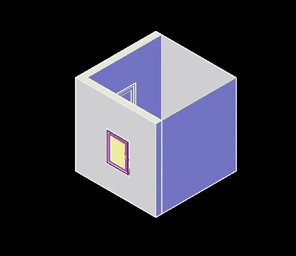
NW isometric view
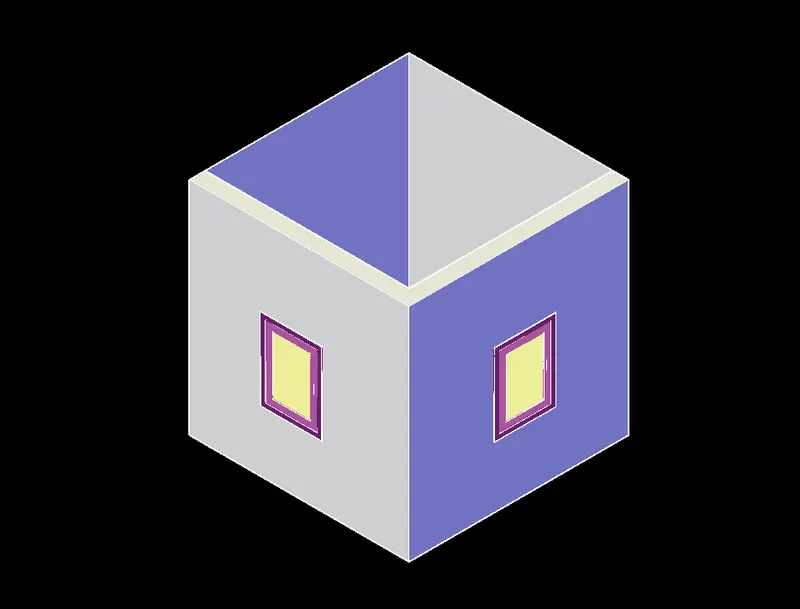
2. Aim: To create 3D view of building facade as per given plan and elevation using Autocad
Steps:
1.Open new file in Autocad 2023, Type UNITS, use Engineering and take inches
2.Then LIMITS, Limits of lower left corner give (0,0) and limits of upper right corner (100',100')
3. Change the settings to 3D modelling
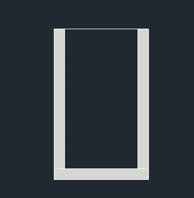
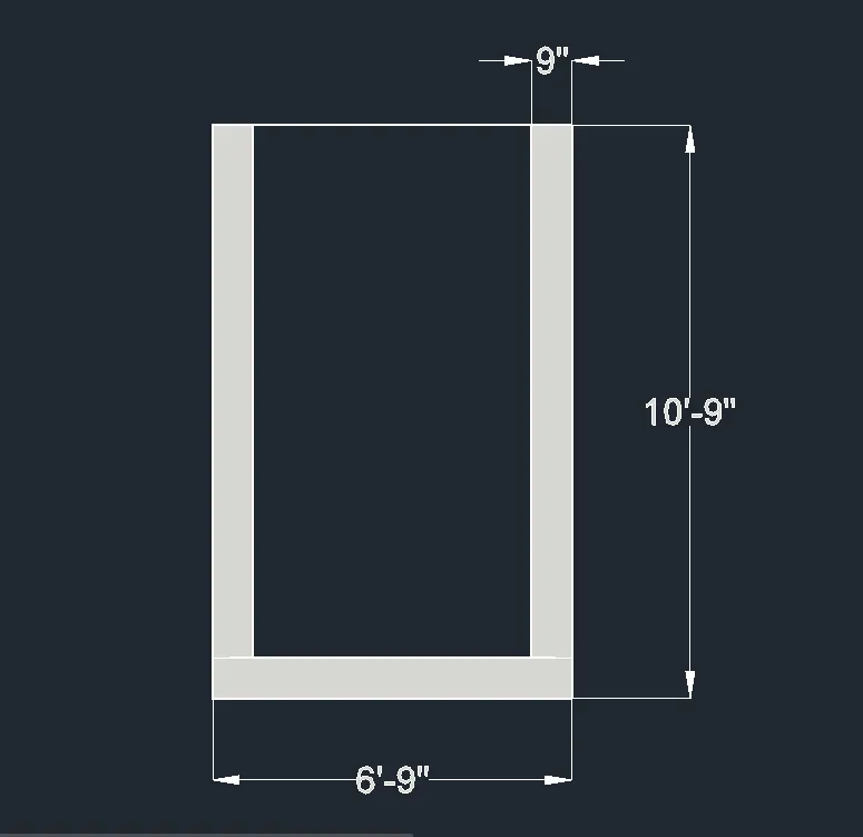
4. Set Top view and draw using line command a rectangular of size 6'9"X10'9"
and Offset it by 9" in inward direction expect the tio horizontal line and trim extra lines
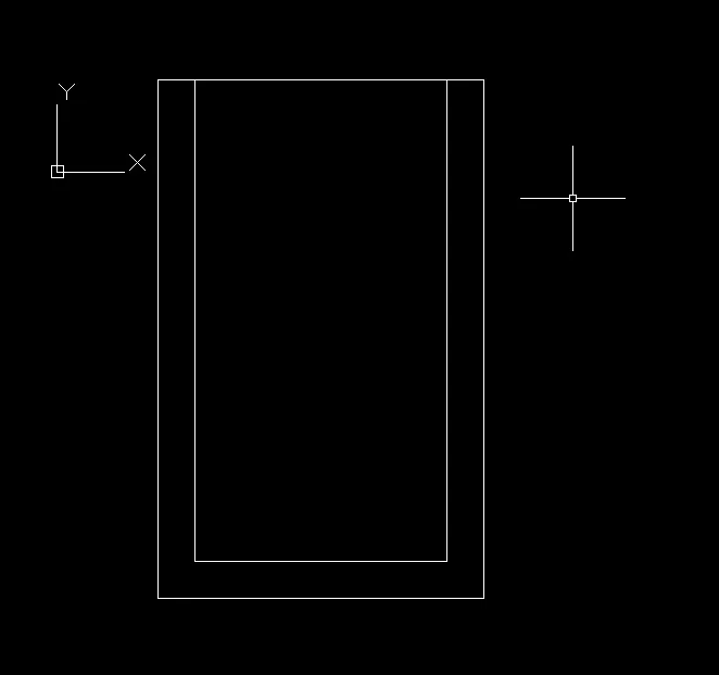
5. Set it in SW isometric view
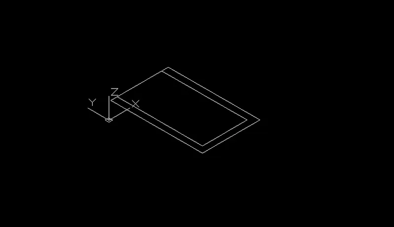
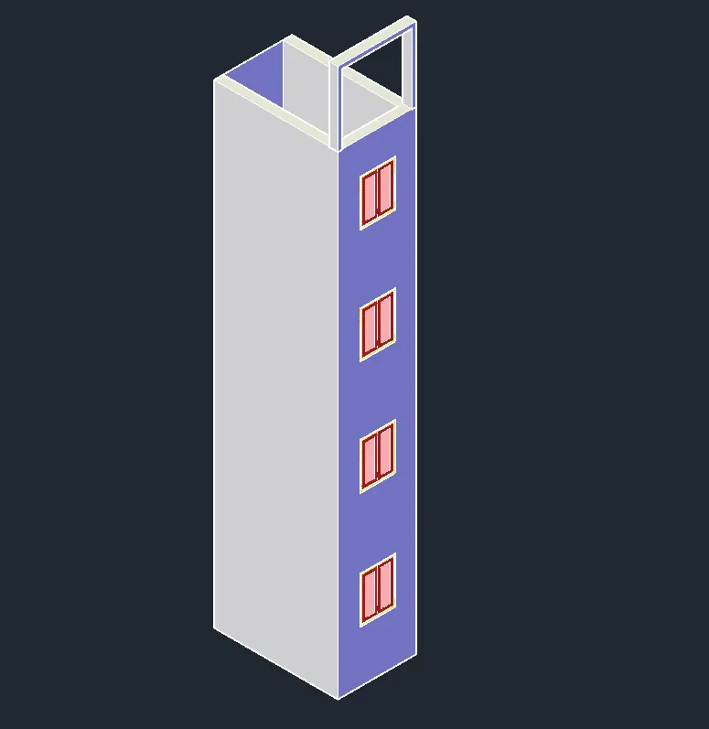
6. By using Presspull extrude it by height of 41'3"
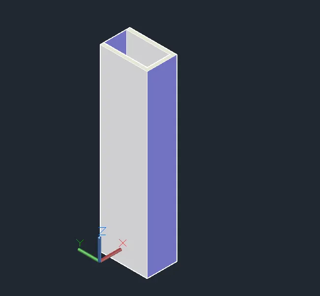
7. To create window:
Change it to Front view
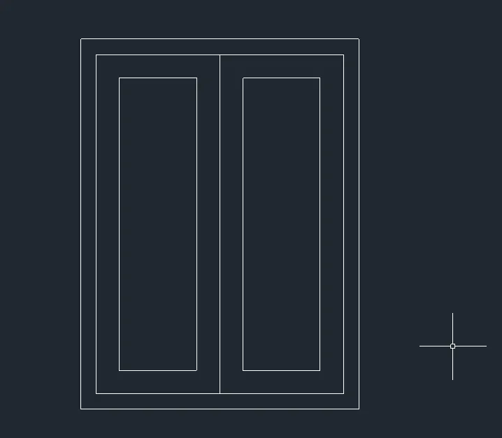
Draw a rectangle using line command by 3'X4' and offset the lines by 2"
and again offset by 3" and then by draw centre line and offset it on both sides by 3"
And Trim the extra lines at corners
Using Hatch provide colours
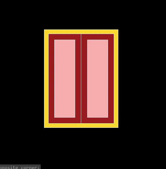
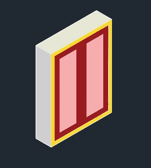
Region all the lines and Extrude it by 9"
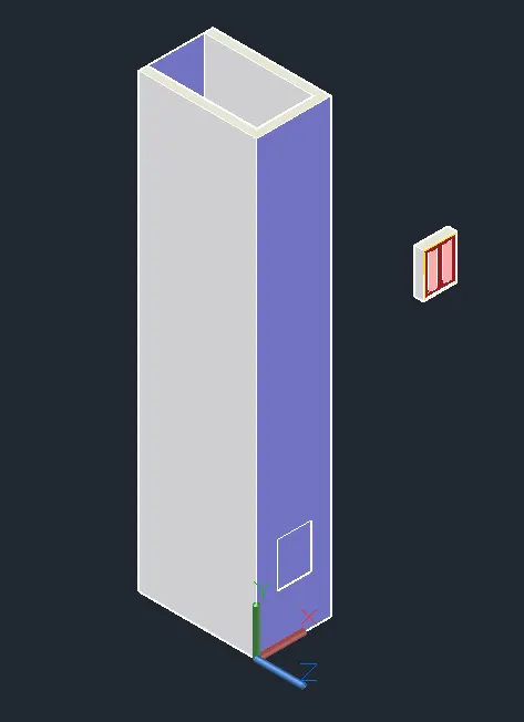
8. Now keep the UCS at the bottom left corner and draw a reference rectagle of size 3'X4'
By giving co-ordinates of rectangle as (1'11",4'6",0) and then opposie corner as (3',4',0)
And Presspull it by 9" in back direction
9. Copy the rectangle and place it in upward direction by distance between is 10'1" , 9'11" and 9'11"
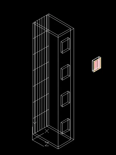
10. Using Subtract Command remove the rectangles
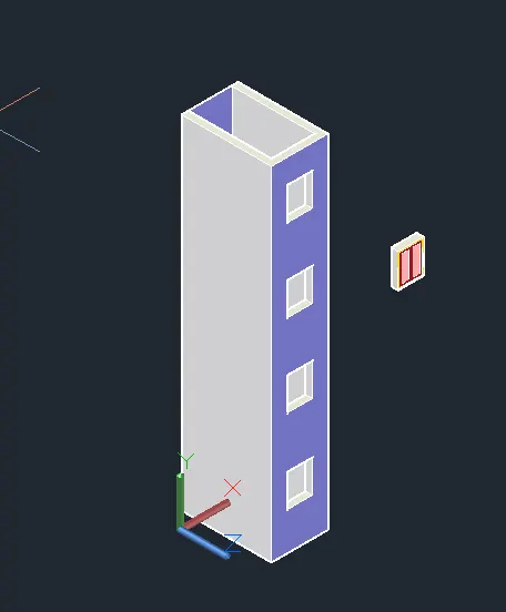
11. Copy and place the created window at the hollow portions
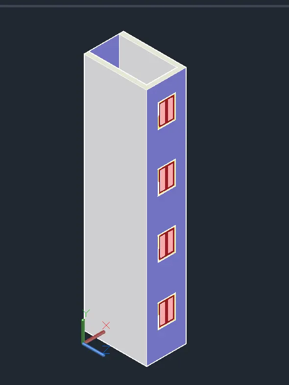
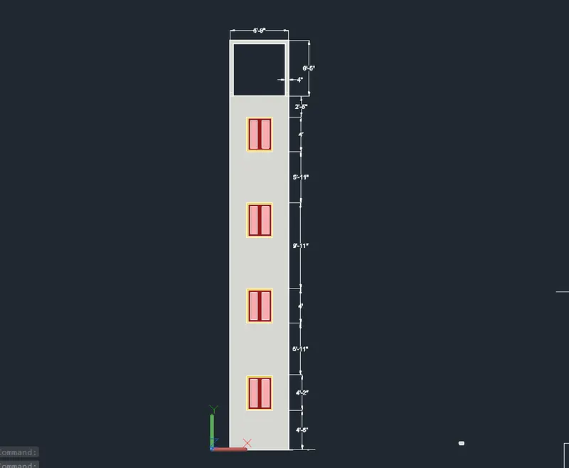
12. Using line command draw the above lines by 6'5" height and 6'9" width
and offset it by 4" in inward direction and trim extra lines
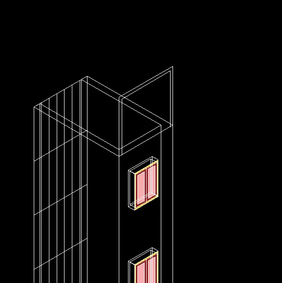
Make region and Extrude by 9" in back direction
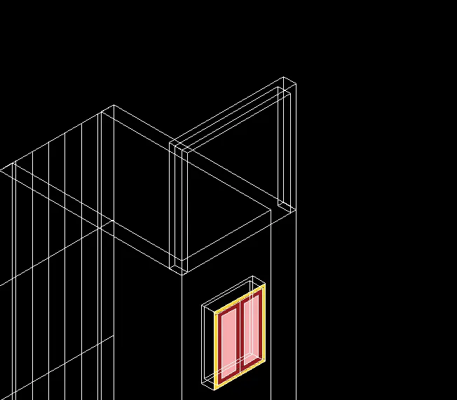
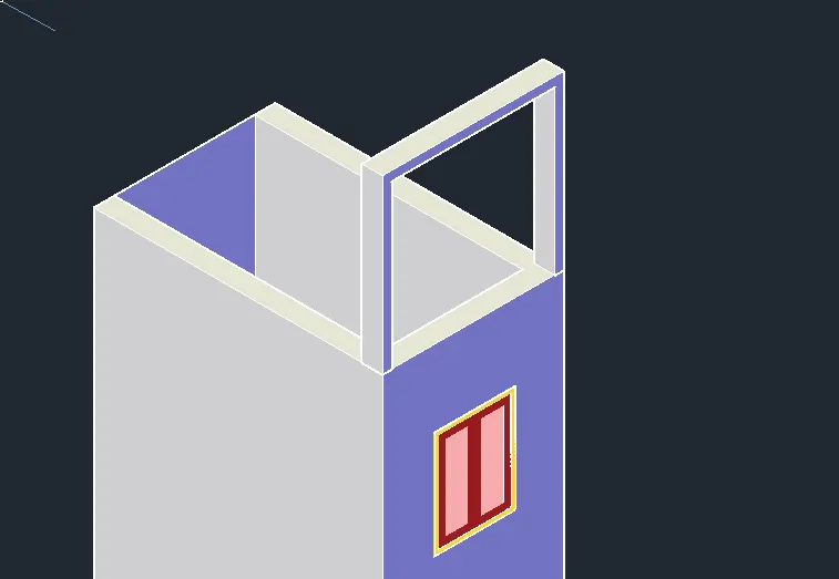
Results:
SW isometric view
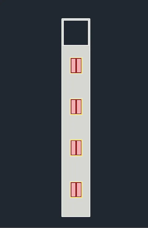
Front view:
Plan: Top view
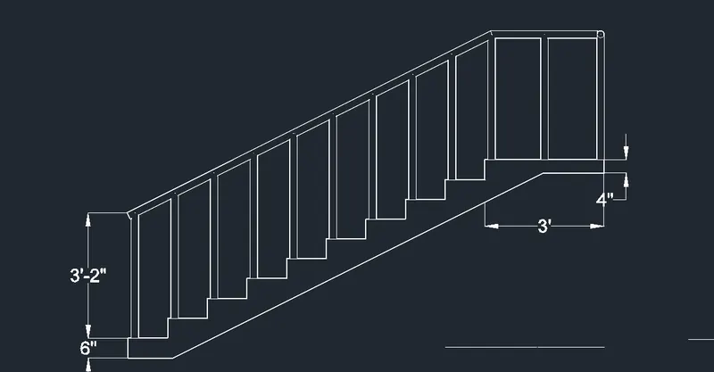
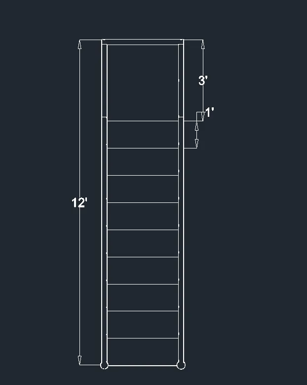
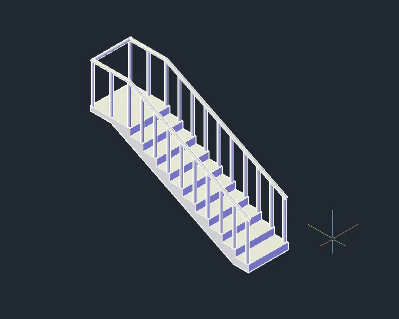
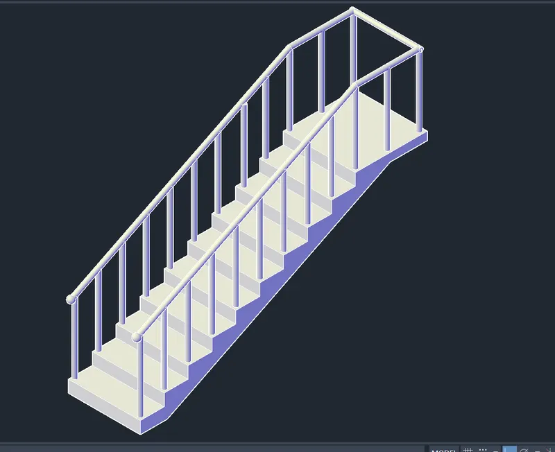
3. Aim: To create 3D view of staircase as per given plan and elevation using Autocad
Steps:
1.Open new file in Autocad 2023, Type UNITS, use Engineering and take inches
2.Then LIMITS, Limits of lower left corner give (0,0) and limits of upper right corner (100',100')
3. Change the settings to 3D modelling
4. Set right view and draw using line command a 6" in Y direction and 1' in X direction
5. Copy and array it for 9 times
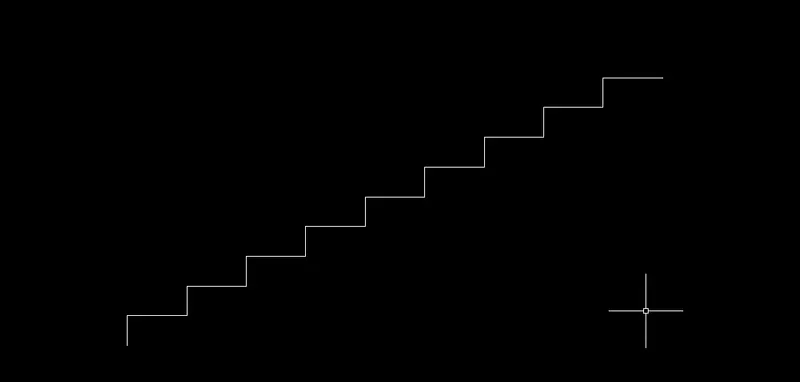
on the top stey draw 6" rise and 3' landing
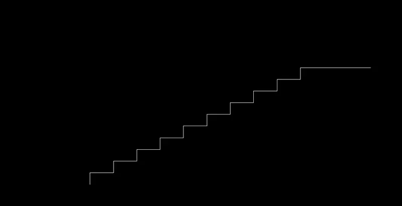
draw reference line and offset it for 6" in down direction and give the thickness of landing as 4"
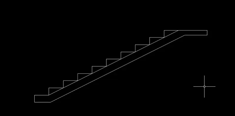
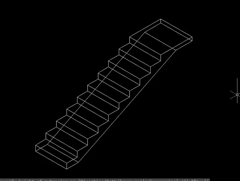
6. Make it region and Extrude it for 3'
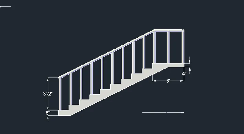
7. To create Baluster: Draw the circle of 1" radius and extrude it for 3'2"
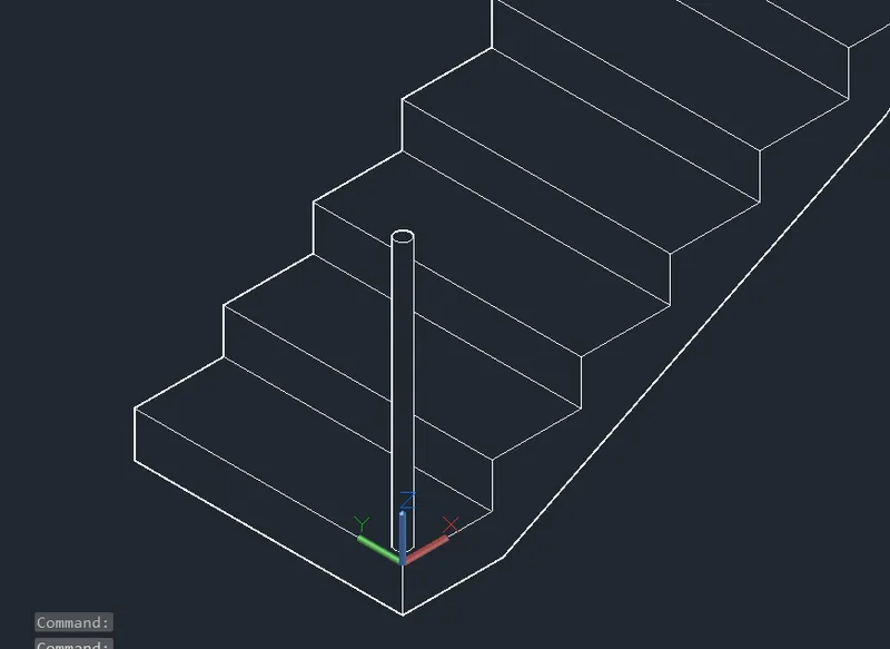
copy it and use array and place
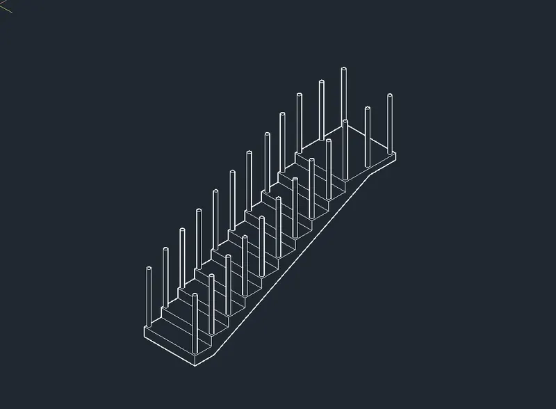
8. Draw a Polyline joining all the centers and draw circle of radius 1" and Using sweep command create the hand rail
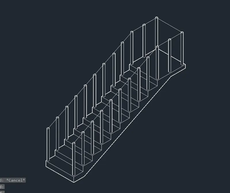
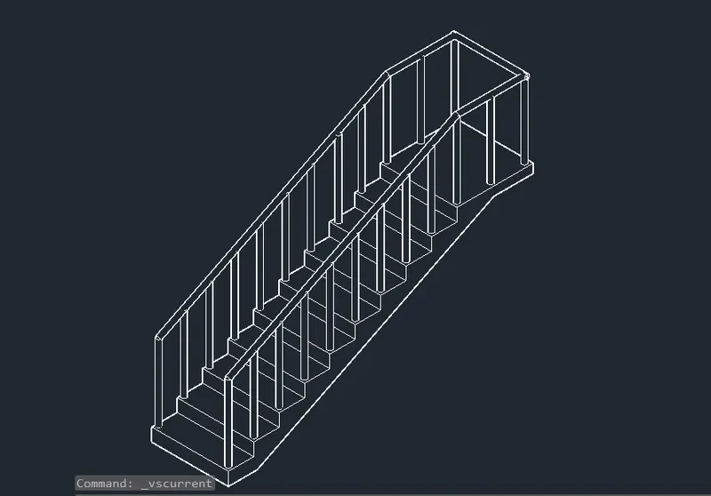
Using Presspull extend the handrails at edges by 2"
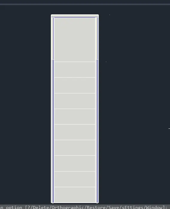
Results:
4. Aim: To create 3D view of wall with spread footing and to create door opening and also providing rendered view as per given plan and section using Autocad
Steps:
1.Open new file in Autocad 2023, Type UNITS, use Decimal and take millimeters
2.Then LIMITS, Limits of lower left corner give (0,0) and limits of upper right corner (10000,10000)
3. Change the settings to 3D modelling
4. Set right view and draw using Xline command draw vertical and horizontal line,
and offset the vertical line by 400,400 in right direction
offset the horizontal line in upward direction by 300,400,400,600,3300
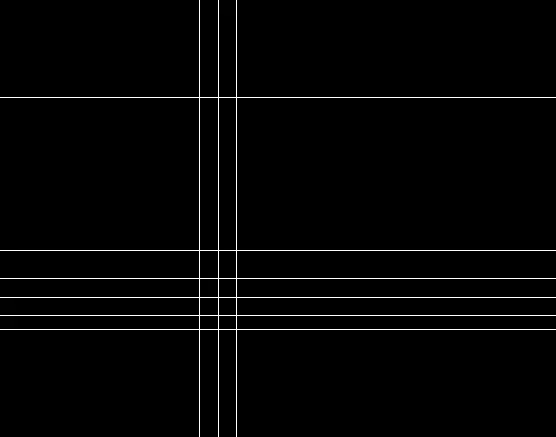
5. Trim the extra lines
offset the mid vertical line on both sides by 250 and again by 200 and then by 150
Trim all the unncessary lines carefully
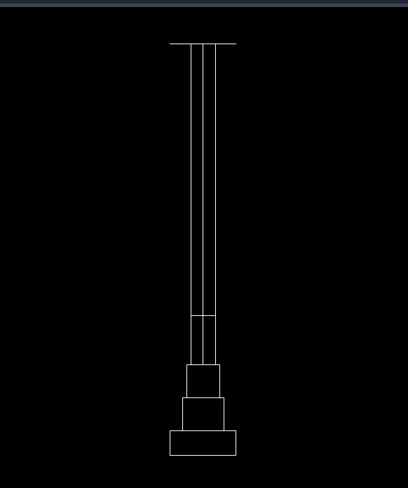
6. Using poly line command draw the draw the slab of thickness 150 and parapet wall height as 1000 and thickness as 150
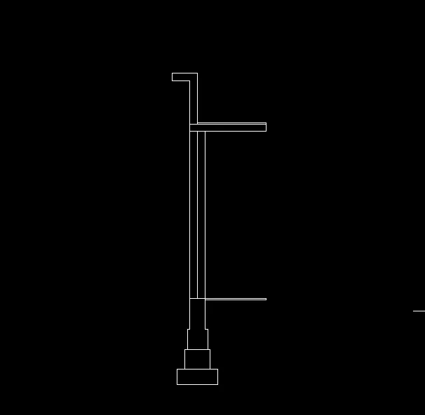
7. Remove the mid reference line
close required boundaries by line command and make it as Region
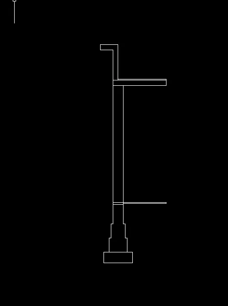
8. Change to SW isometric view and Extrude it by 7500
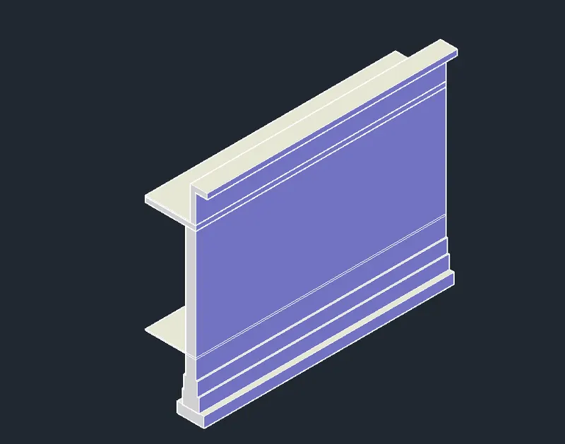
9. To create door:
Change to Front view
Using line draw a rectangle of 300X2100
Draw mid vertical line and offset on both sides by 25 and remove mid line and amke region that rectangle
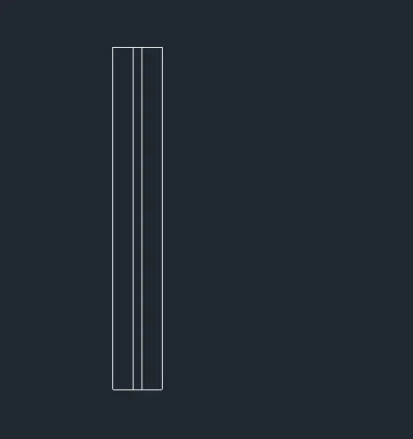
Draw the lintel beam of thickness 150 as per given dimension using Pline
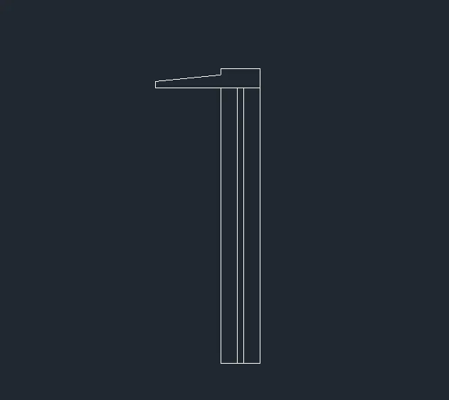
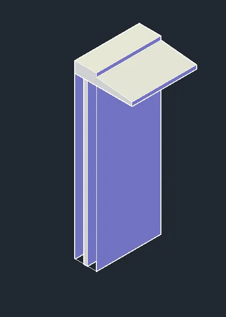
Change to SW view
Make region and Extrude it by 900
10. Place the UCS as shown below and draw a rectangle by giving co-ordinates as (3300,600) and (900,2250)
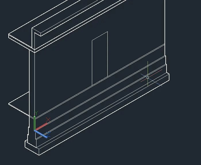
Press pull the drawn rectangleby 300 in back direction
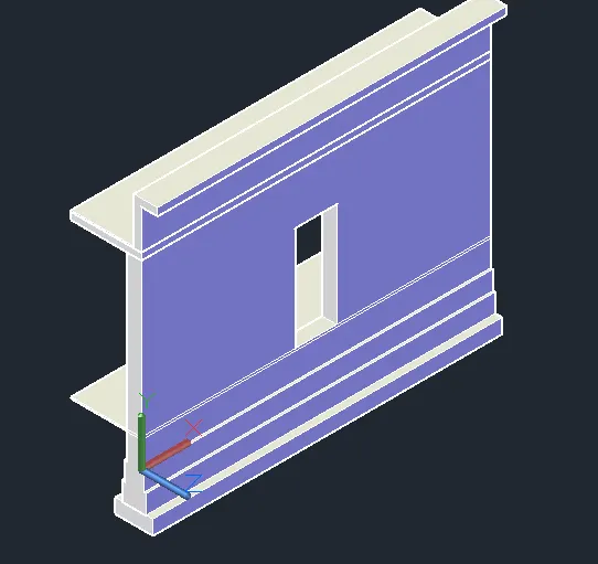
11. Presspull the lintel by 200 on both sides
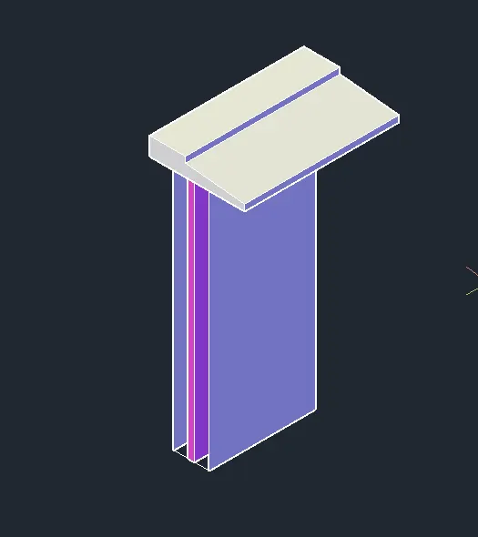
12. Place the Door in the opening created in wall by using Copy command
Delete the surfaces front and back of door
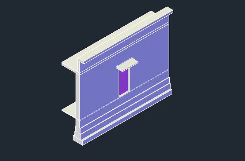
Front view
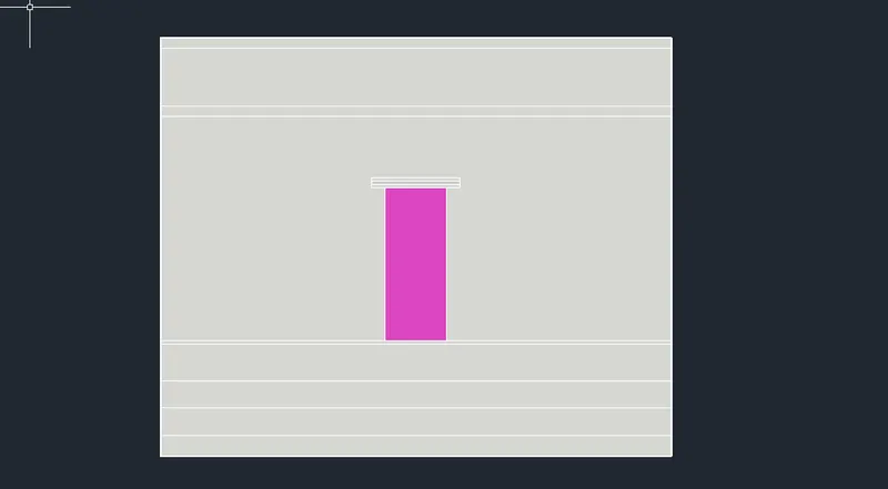
SW isometric view
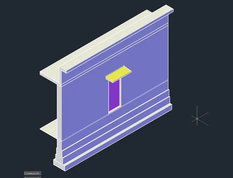
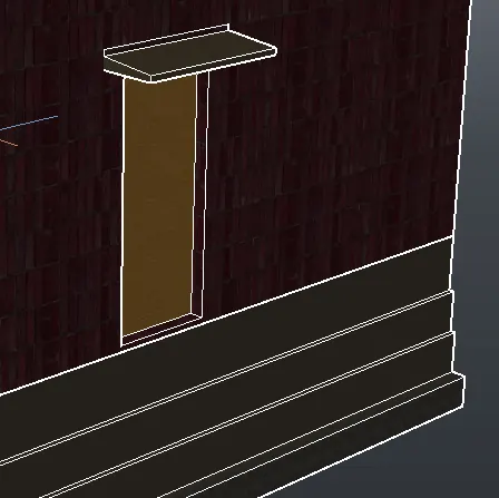
13. Goto Material browser and assign differnt materials
Provide brick masonry to wall and parapet wall and wood to door , and concrete for footing
Provide Floral carpet to the inside flooring
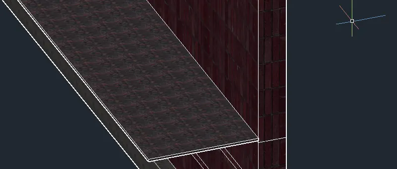
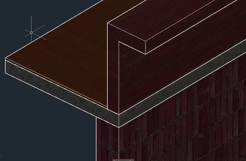
Provide concrete to slab and floor finishing to floor
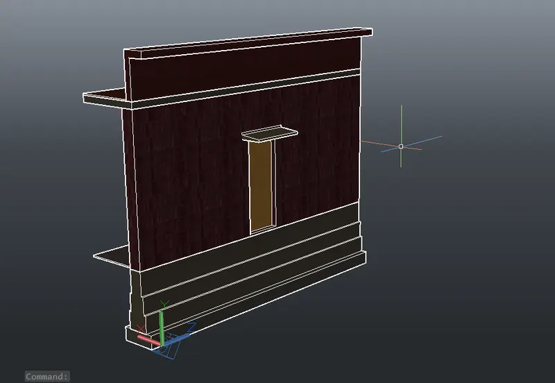
14. Set the background as village and then render
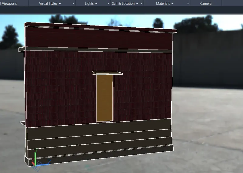
Results: Final rendered image