Creating 3D Isometric view of various structural elements in AutoCAD
CHHLANGE 13
1
AIM: To create a 3D isometric view of the building.
INTRODUCTION: To create a 3D isometric view of the building with plan and elevation with their dimensions and to use the materials give the building for rendering purpose.
PROCEDURE:
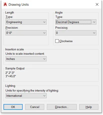
1.Open auto cad and set unit of the drawing
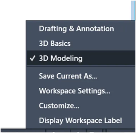
2.Go for a 3D modeling
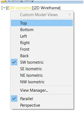
3.Then go for top view
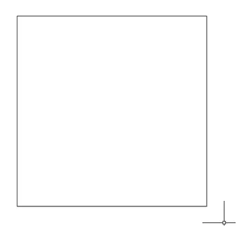
4.Create a rectangle 10’9”x 10’9”
5.Offset 9” inner side
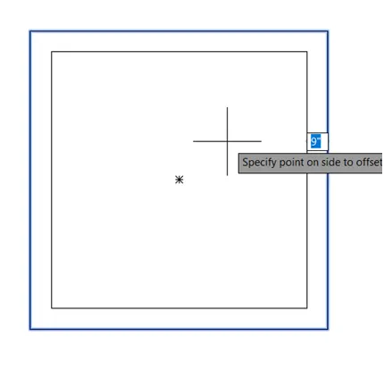
6.Trim the both side portion of the inner rectangle
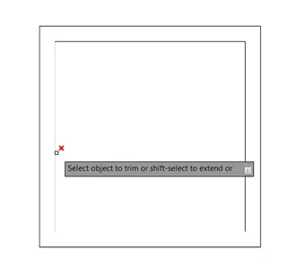
7.Extend the both line to the outer rectangle
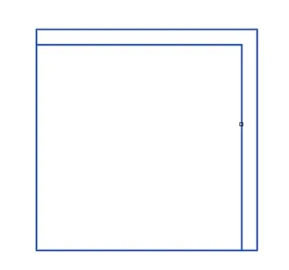
8.Draw a midline of the both wall section
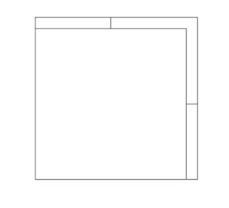
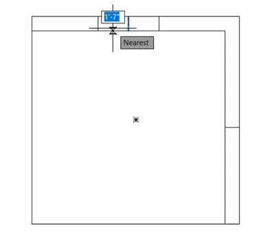
9.Go for offset 1’7” both side for window of the wall
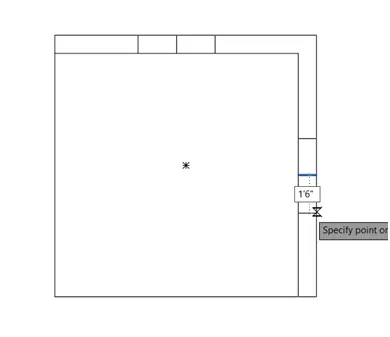
10.Go for second wall and offset 1’6” both side for another window
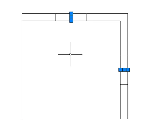
11.Delete the mid line of both side
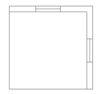
12.Create a mid line for the sown both window
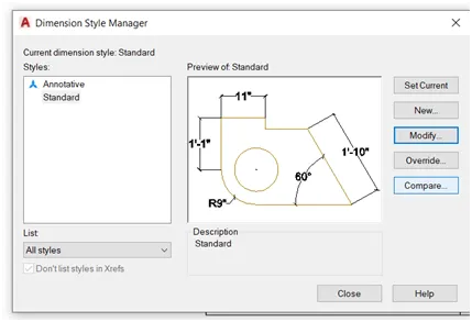
13.Set the dim style for the shown dimension
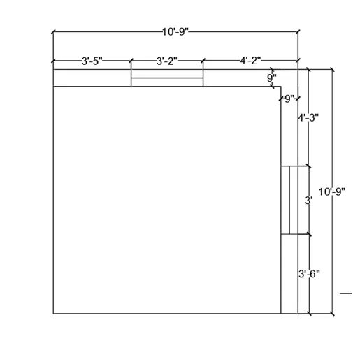
14.Give the dimension of the wall
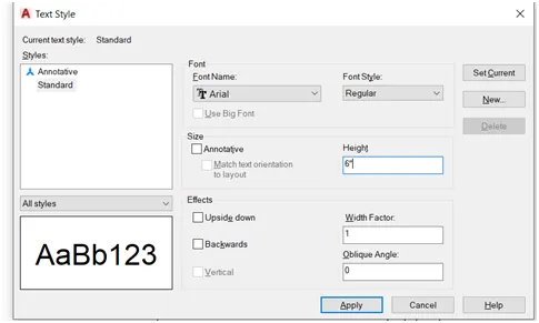
15.Set the text style
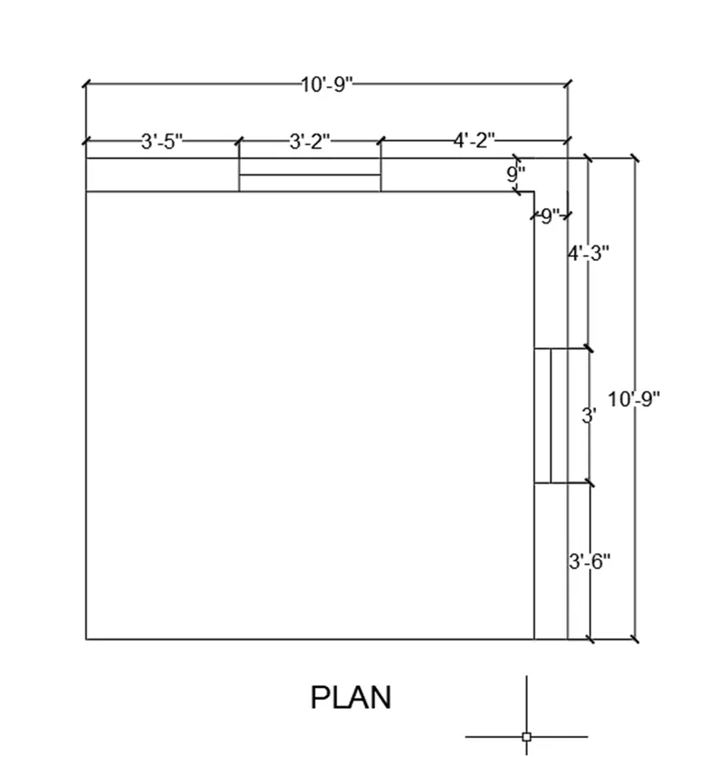
16.Then give the name of the drawing
17.Go for 3D view and crate a box which is 10’9”,9”,10’
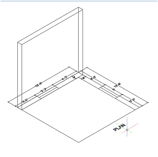
18.Create a same as another wall
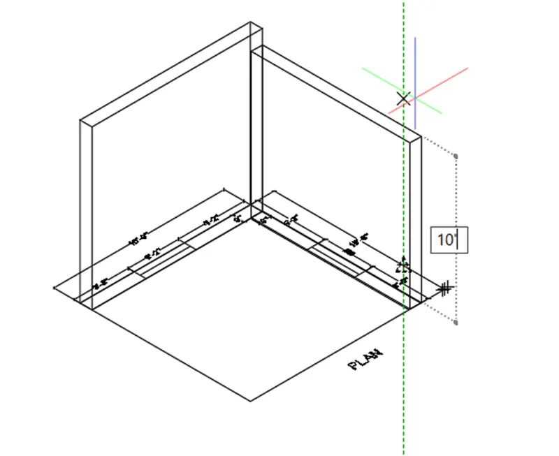
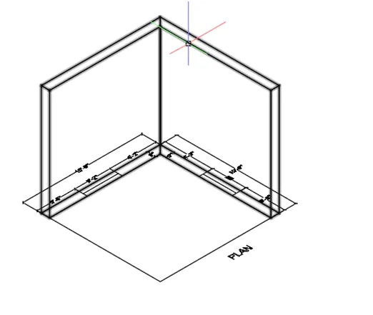
19.Go for union command and join the both wall
20.Createa a window 3’2”,9”,4’
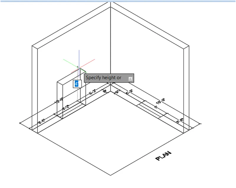
21.Create another window 3’.9”,4’
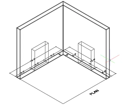
22.Move the sill level of the window 3’ height then subtract the window of the wall portion
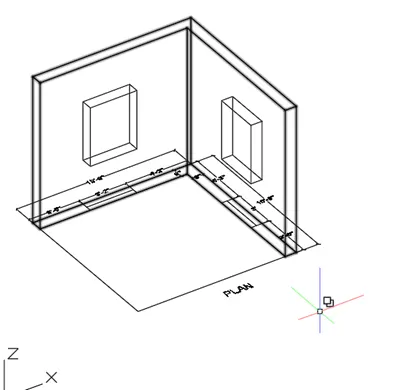
23.Go for shaded view
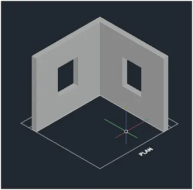
24.Then crate a window as given the diagram to create a 3 boxes size is 6” smaller then last window
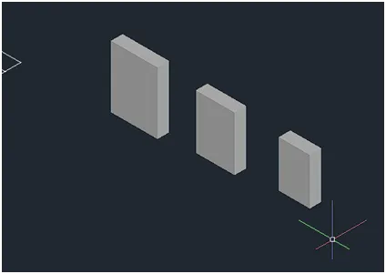
25.Then subtract to each other small to big
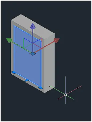
26.Just look like that
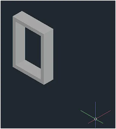
27.All window look like that Then explode the smaller both boxes
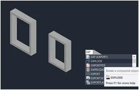
28.then delete the outer surface
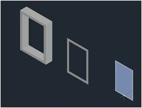
29.Then hallow box extrude 7”
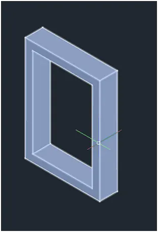
30.Then place the mid of the first hallow box
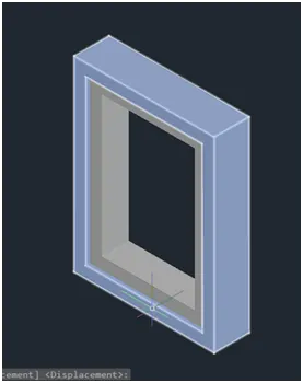
31.Then place another surface then the window is ready
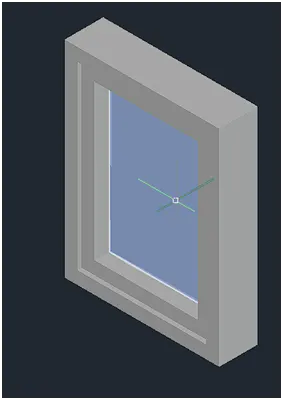
32.Define the material of the window or color of the window for rendering purpose
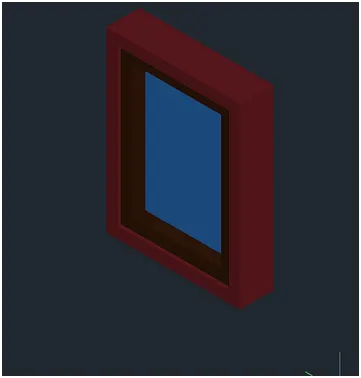
33.Then place the window from wall
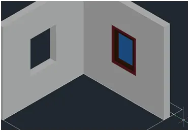
34.Same as another window crate and place the another window Then define the material of the wall and create a top lintel portion of the building 9”thick
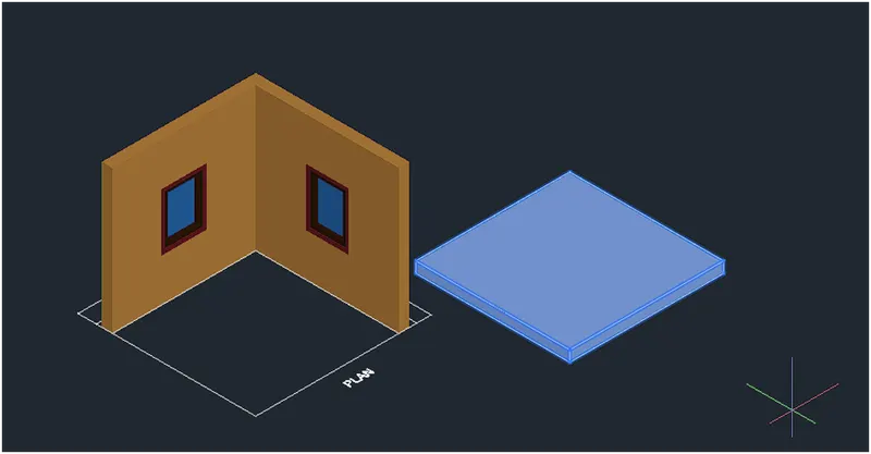
35.And place the top surface and create a bottom surface 4” thick
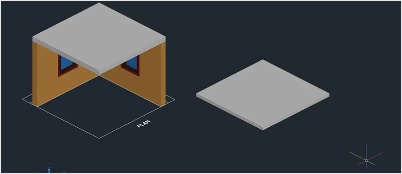
36.Place the bottom surface
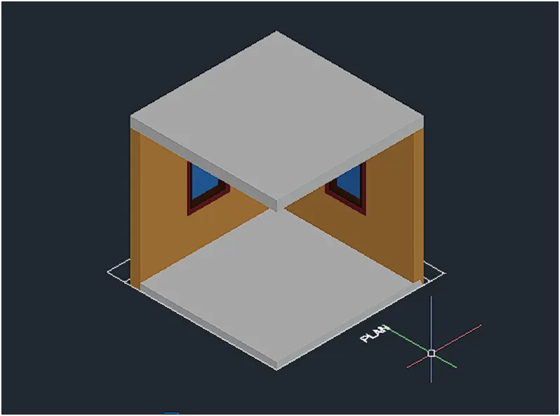
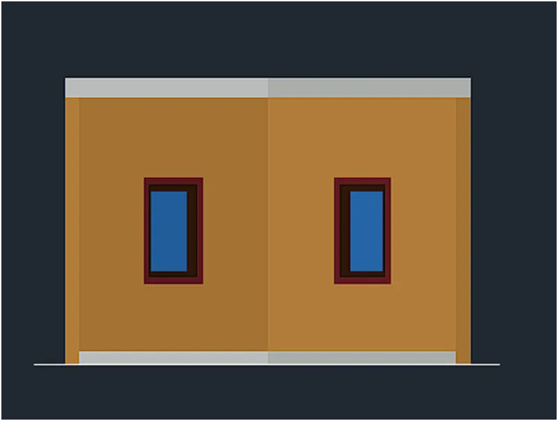
37.This is a front view of the building
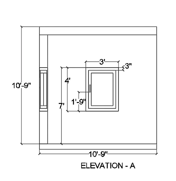
38.This is a back view of the building in 2d wireframe or elevation of A portion
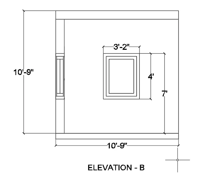
39.This is a side view of the building in 2d wireframe or elevation of B portion
RESULT: Drawn the object at a given dimensions and also define the materials or color.
2
AIM: To create a 3D isometric view of the multistory building.
INTRODUCTION: To create a 3D isometric view of the building with plan and elevation with their dimensions and to use the materials give the building for rendering purpose.
PROCEDURE:
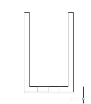
1.Go for a top view and create a box 9”,10’9”
2.Again box 6’9”,9”
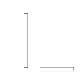
3.And place the corner as shown in figure
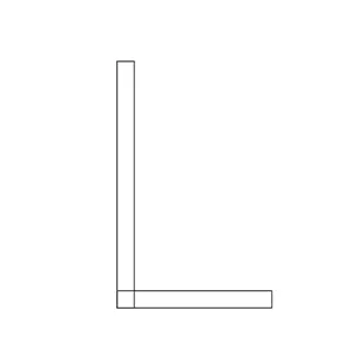
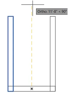
4.then mirror the left side box at right side
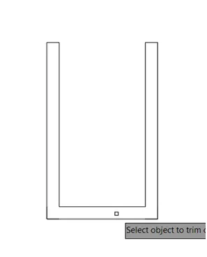
5.Then trim the cornet lines
6.Deaw a window through line or offset command create a mid line and offset both side
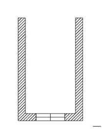
7.The create a mid line and hattch both wall portion
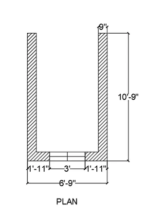
8.Then give the dimension of the plan
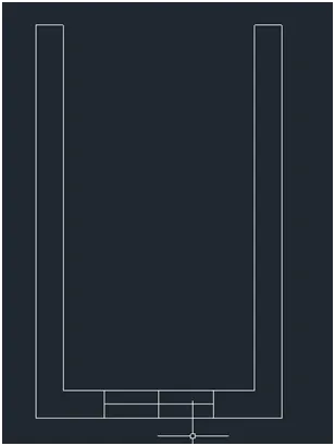
9.Go for shaded view and copy the object and delete the hatch
10.Create a region
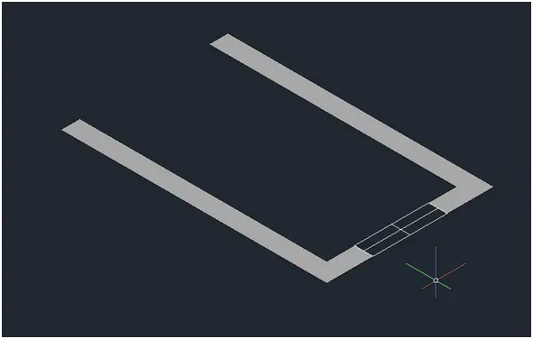
11.Delete the mid lines and create a rectangle
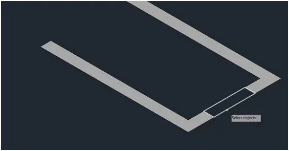
12.Then extrude the surface
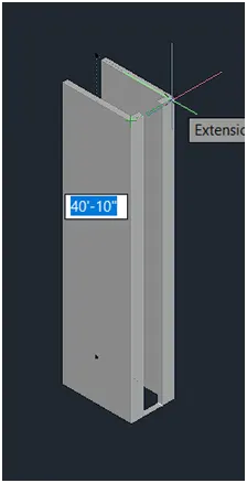
13.Same as mid portion create a region and extrude the surface and use the union command for a single object
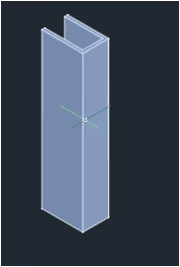
14.Create small boxes as top portion as same as given section of the drawing
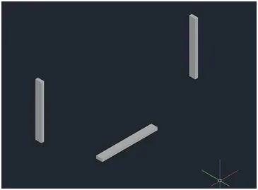
15.Then connect these three boxes.
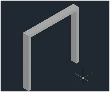
16.Then use the union command for a single object
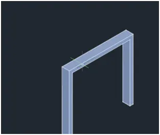
17.Then place the top of the building
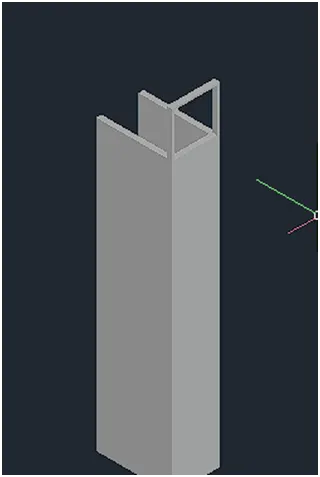
18.Create a boxes for drawn a window The size of boxes as given window pannel
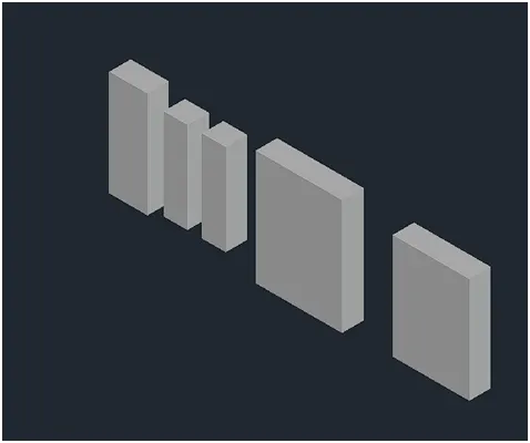
19.Copy the all boxes
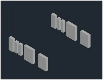
20.Then subtract the boxes small to big as shown in figure
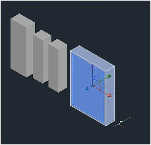
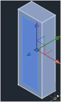
21.Then place the window as given section of the drawing
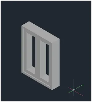
22.Place the mid surface of the window
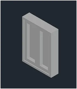
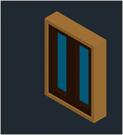
23.Then define the material of the window for rendering purpose
24.Go for a 2D wireframe and plane
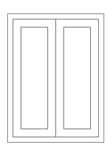
25.Give the dimension of the window
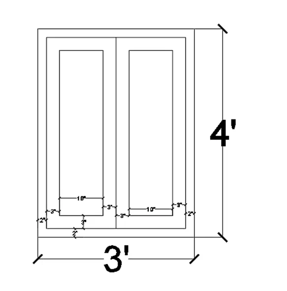
26.Then place the window as a given distance of the drawing
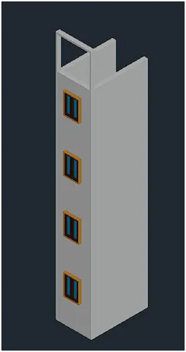
27.Go for a 2D wireframe and plane
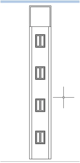
28.Difne the dimension of the drawing
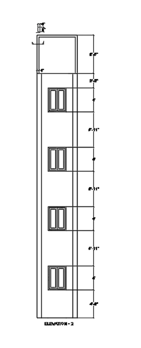
RESULT: Drawn the object as a given dimensions and also define the materials or color.
3
AIM: To create a 3D isometric view of the stair and railing.
INTRODUCTION: To create a 3D isometric view of the stair shown in plan and elevation with their dimensions and to use the materials for the rendering purpose.
PROCEDURE:
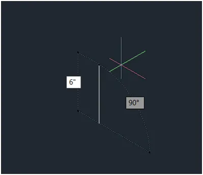
1.createa a vertical line 6”
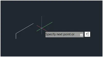
2.create a horizontal line 1’
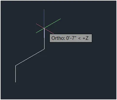
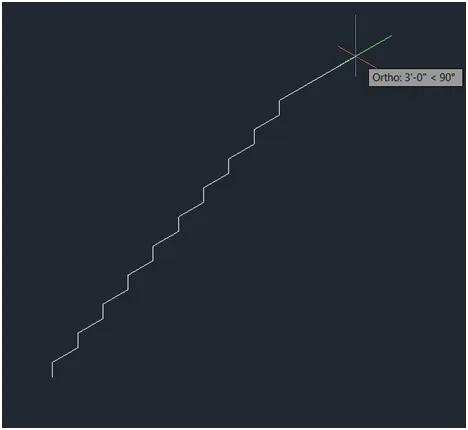
3.Create to continue t vertical 6” and horizontal 1” fallow the step at 9 times
4.Then draw the landing 3’ as given drawing
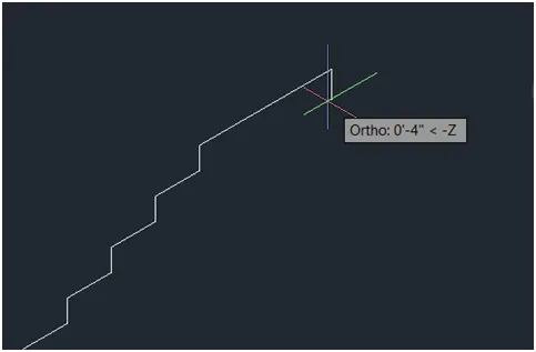
5.Go for down 4”
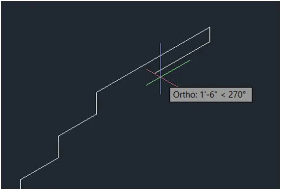
6.Back side 1’6”
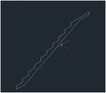
7.To join the bottom line
8.Then go for the negative direction 4’ as shown in figure
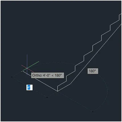
9.Mirror the object at mid of the line
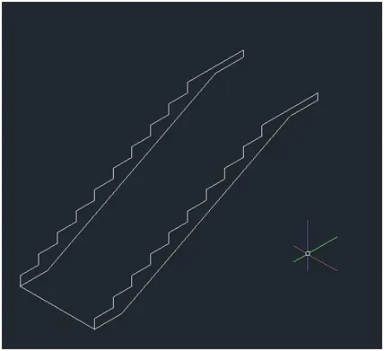
10.Then join the line as a some step It is ready to isometric view of the stair portion
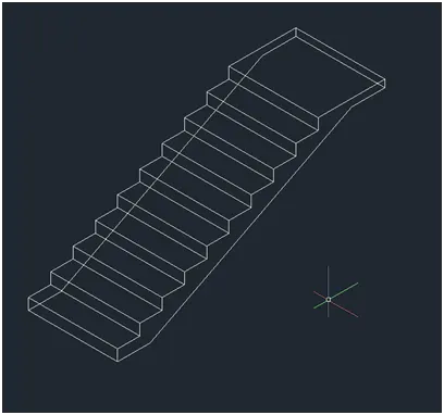
11.Create a balusters create a up word line 3’2”and offset the line 2”and join the both line
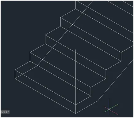
12.Then copy the object and place the each step of the
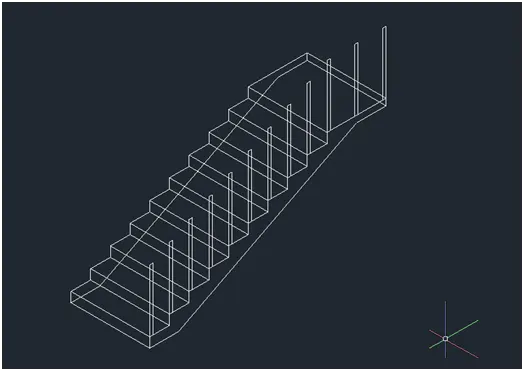
13.Then create a hand rail which is 4” thick
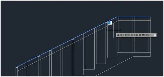
14.Then trim the intersection or inner portion of the hand rail
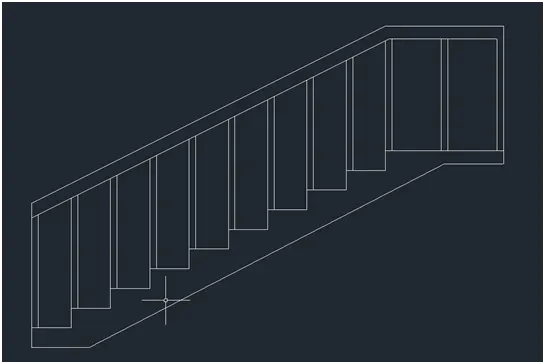
15.Then copy the object another side and go For 2D wireframe
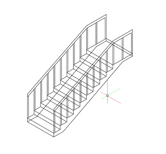
16.Go for the plane and give the dimension of the staircase and name
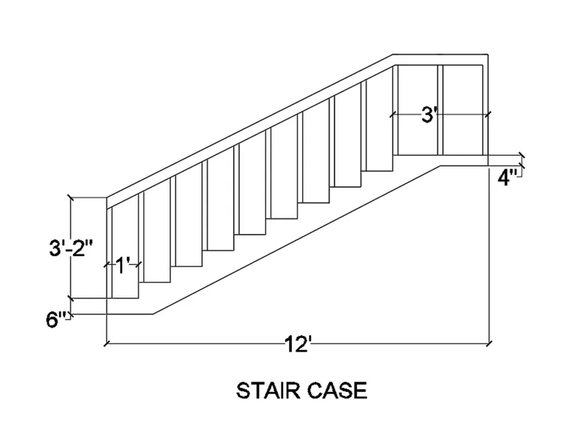
17.Go for a top view of the drawing and show the dimension of the drawing
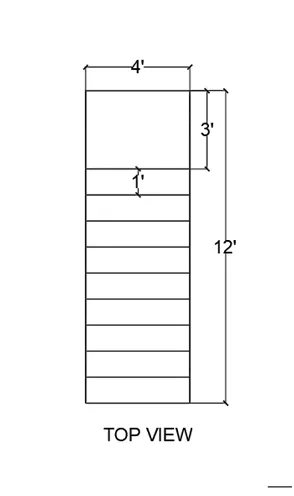
18.Go for a side view and create a region of the drawing and extrude the region the region is individual for railing blasters and stair step portion Then extrude the region.
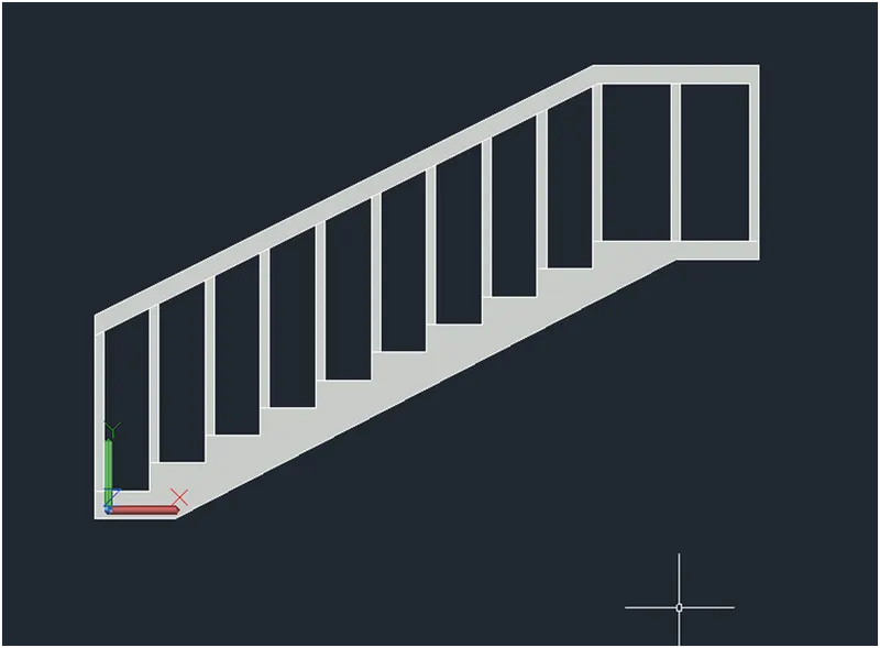
19.Then mirror the hand rail and blaster for another side
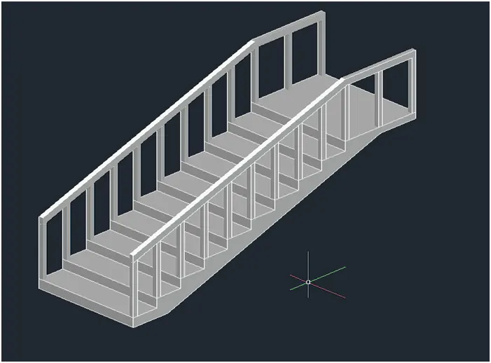
20.Then give the material of the stair for the rendering purpose
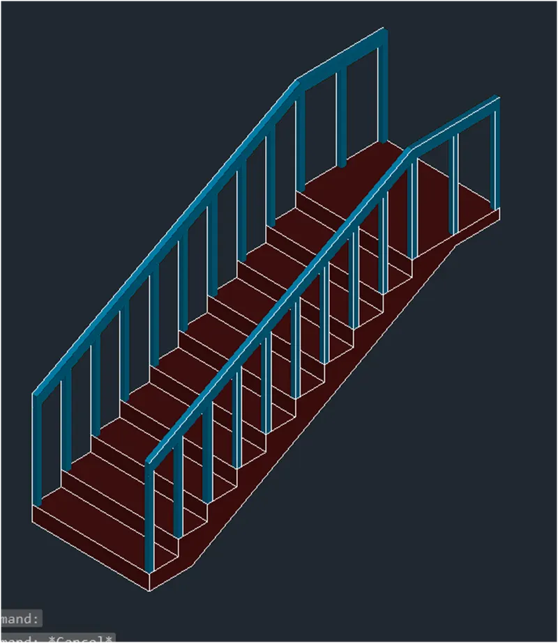
RESULT: In this drawing I am creating a 3D isometric view in the use of line command and also use of solid view.
4
AIM: To create a 3D isometric view of the wall with footing.
INTRODUCTION: Create a 3D view of a Wall and spread footing. Create the Door opening and show the plans and elevation for the details. And create a rendered view of the model with materials.
PROCEDURE:
1.change the unit of the drawing in mm Then create a box 300,7500
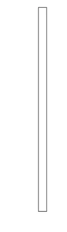
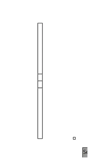
2.Create a mid line of and offset 450mm bothe side and trim the mid portion
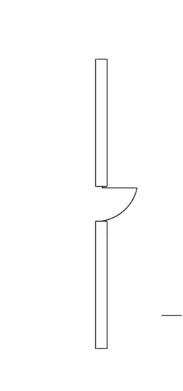
3.create a door symbol for door opening
4.Then create a line distance which is 50mm two times and 150mm one times and join the all lines then mirror the another side of the wall as shown in figure
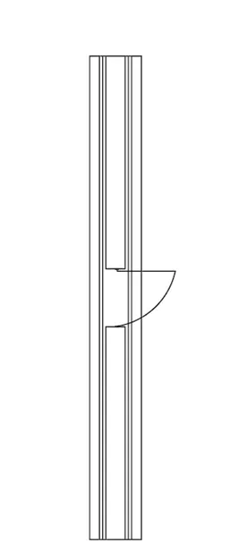
5.Then create a boundary and hatch that portion the delete the boundary
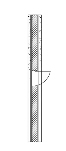
6.Then create a section and dash line at cantilever portion Then give the name
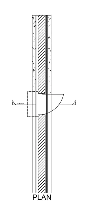
7.Then give the dimension of the drawing

8.Go for isometric view shaded
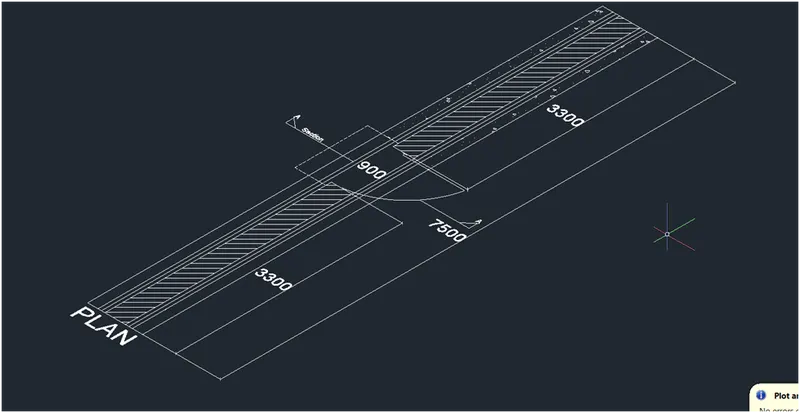
9.create a box which is 300,7500,3300mm
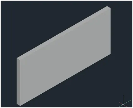
10.crate another box which is 300,900,2100mm
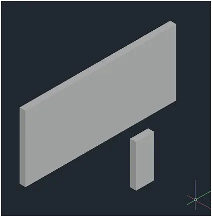
11.Then subtract the box at mid portion of The wall.
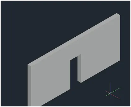
12.Then create another surface 50mm and place the wall two times and one times 150mm
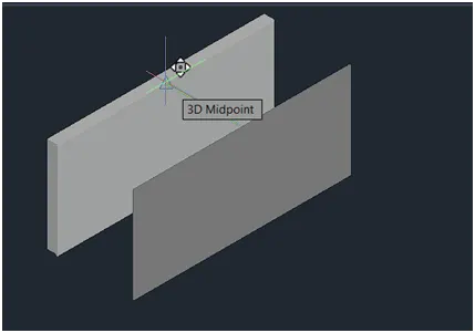
13.Then create a box at cut the door portion
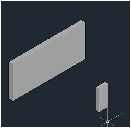
14.Then subtract the door potion
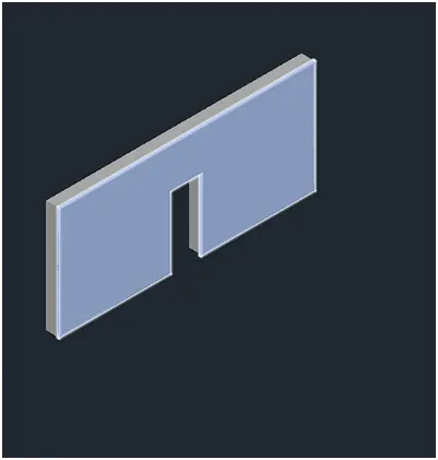
15.Then mirror the last three surface to another side of the wall
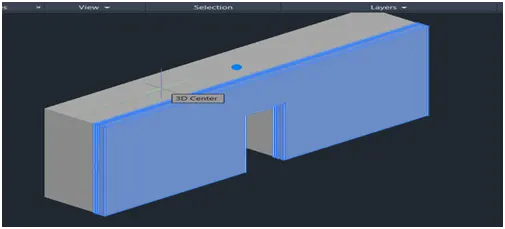
16.Create a cantilever surface and give region and extrude the surface
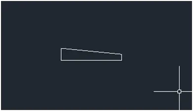
17.and place the top of door
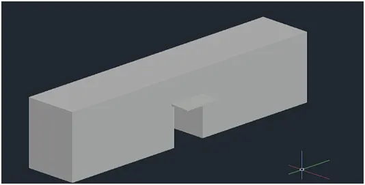
18.create a box as a size of door
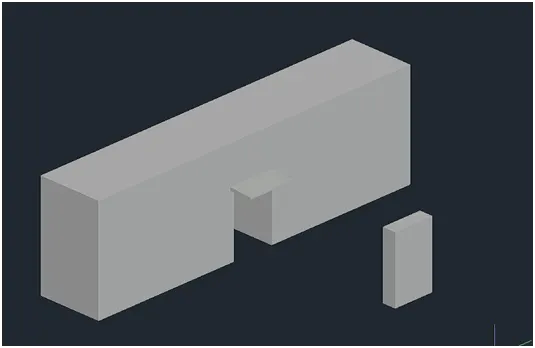
19.And place of the mid of the door
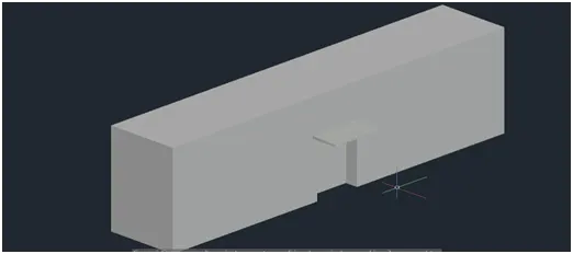
20.Define the color of the wall or material of the wall Then go for a render
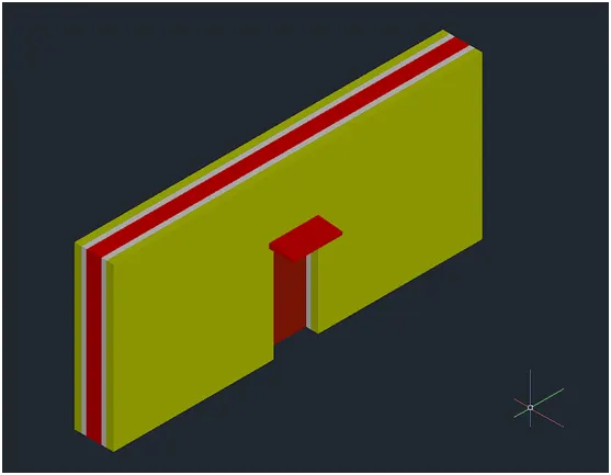
21.Cross section view of the wall
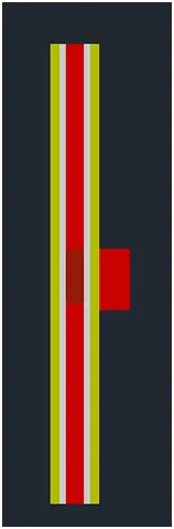
Section of the wall
22.Create a rectangle 700,300mm
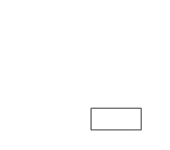
23.The again create a rectangle and place at mid of the footing which is 500x400mm, 400x400mm,300x600
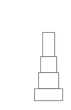
24.Then trim the mid line as shown in figure
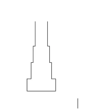
25.Then create a rectangle 300x50mm
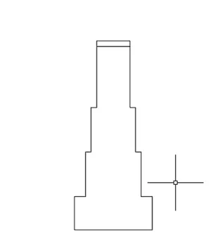
26.Then again create rectangle 100x2100mm and mirror the other side
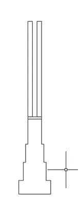
27.Then create a cantilever portion through poly line
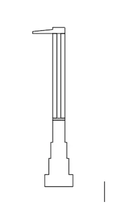
28.Then again create a rectangle 300x1050mm and above create a line and offset 150mm and join the line and create a above portion of the as a parapet wall through poly line
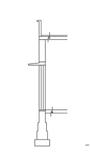
29.Then hatch the wall and footing.
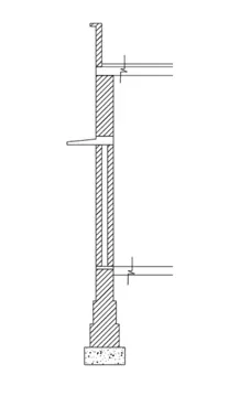
30.Give the dimension of the drawing.
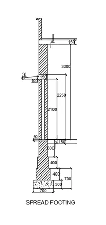
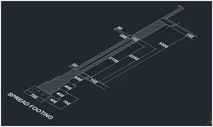
31.Go for isometric view
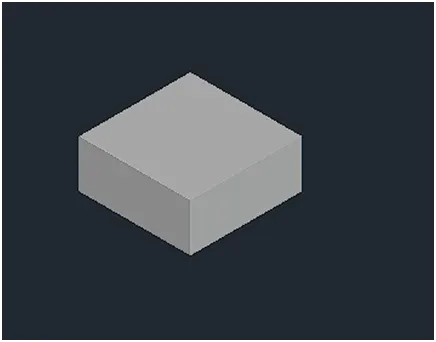
32.Create a box of the footing 700,700,300mm
33.create another box of the size of the footing and place the mid of the footing as shown in figure
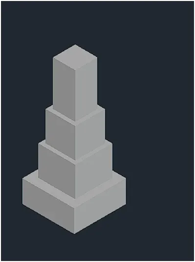
34.Then create a cut portion of the wall go for a box 100,300,2100mmand mirror the another corner
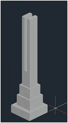
35.Then create a cantilever and create a region and extrude 300mm then place of the wall
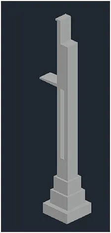
36.Then create a above box as a given dimension and place the top of the wall
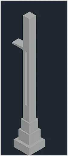
37.Then create a above portion of the wall
38.Go for a material and define the material and go for a render.
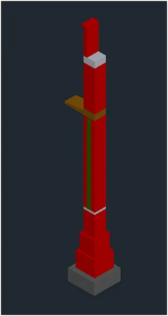
RESULT: In this drawing I am creating a 3D isometric wall section or elevation of the wall section and define the material of the wall of color of the wall and also create a isometric cross section of the wall with their footing.