Creating 3D Isometric view of various structural elements in AutoCAD
1. Create a 3D Isometric View of the building with plan and elevation given.
Aim: To create a 3D Isometric View of the building with plan and elevation given as per the figure.
Introduction: The given drawing consists of a plan and elevation which is to be created in 3D Isometric view. The given drawing is first drawn in 2D and then converted to 3D Isometric view. Initially the plan is drawn in 2D and the elevations are provided by 3D view. The drawings are drawn in Imperial system as the given drawings are in feet and inches.
Steps:
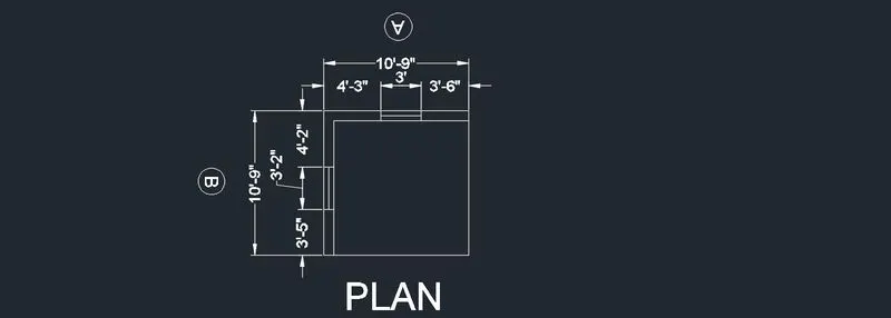
- The given plan is drawn by rectangle command.
- A square of 10'-9" is drawn initially and xplode command is used to explode the square drawn
- Further to provide wall thickness offset command is used and offset of 9" is done.
- Then to provide windows again offset command is used.
- For providing windows at A & B direction offset is done as per the given distance and size and extra lines are trimmed off using the trim command
- Then after defining the dimension and text style the dimensions are marked using dimlinear and dimcontinue command and texts are provided as per the requirement using mtext command.

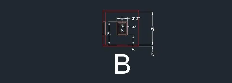
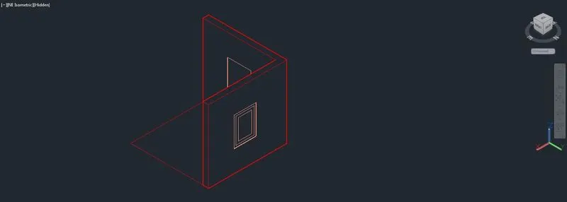
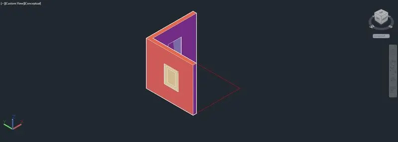
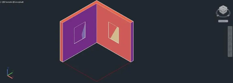
- After creating the plan figure the view is changed from top to default Isometric view.
- Then using the region command regions are created and using extrude command the walls alone are extruded to a height of 10'.
- After that the created windows are moved using the move command to height of 7' i.e the sill level.
- Then using the extrude command the windows are extruded in downwards direction to a distance of 4' and the top and bottom of the windows are extruded to provide remaining walls
- Using union command all the walls and windows are united and the windows are subtracted from the surface of walls using the subtract command.
- Two layers are created from the ribbon walls and windows and are assigned to the figure created
- Finally to provide elevation views are changed and dimensions are marked and provided.
Results: The given plan view created and 3D Isometric view is provided sucessfully and different views with hidden and conceptual views are provided.
2. Create the 3D View of the Building Façade as given in the plan and elevation. Also, see the detail of the window.
Aim: To Create the 3D View of the Building Façade as given in the plan and elevation.
Introduction: The given figure consists of a plan and elevation. The details of the window are also given. The given elevation figure is assumed to be as 4storey building and the windows are created as per the detailing of the windows given. The given drawings are drawn in imperial system as the given figure is in feet and inches.
Steps:

- Intially the plan is created at the top view, using the rectangle comand a rectangle of size 6'-9" x 10'-9" is drawn.
- Then for providing thickness of the wall offset command is used, at a distance of 9" offset is done.
- Windows are als provided by offset command as per the distance given and the extra lines are trimmed off using the trim command.
- Hatch is provided using the hatch command and hatch scale is fixed as per the requirement.
- After defining the dimension and text style, dimensions are marked using dimlinear and dimcontiue command and texts are provided as per the requirement using mtext command.

- For elevation drawing using xline command projection lines are drawn from the plan to fix the boundaries of the elevation figure.
- Window is created as per the detail of the window given by rectangle command, rectangle of size 3'x4' is drawn and the projection of window doors are provided by offset command.
- A horizontal line is drawn in the projection lines drawn and using the offset command the top of the elevation figure is fixed.
- The window created are copied and placed at the heights of the each floor sill level as per the given figure.
- Then using the dimlinear and dimcontinue command the dimesnions are marked.
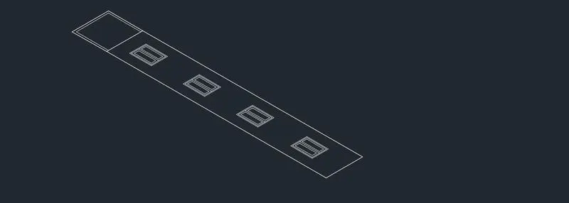
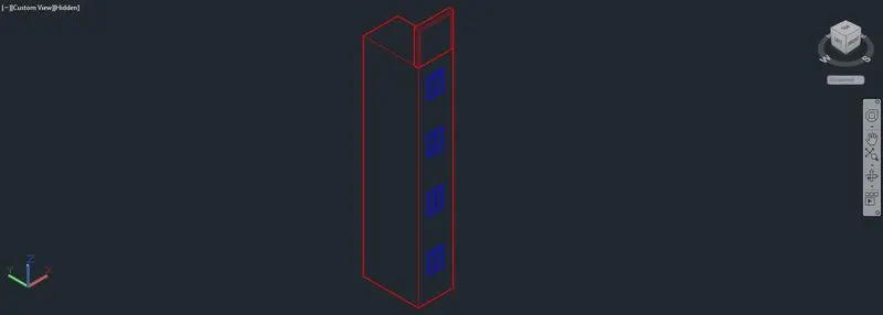
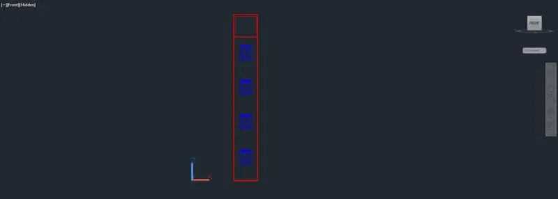
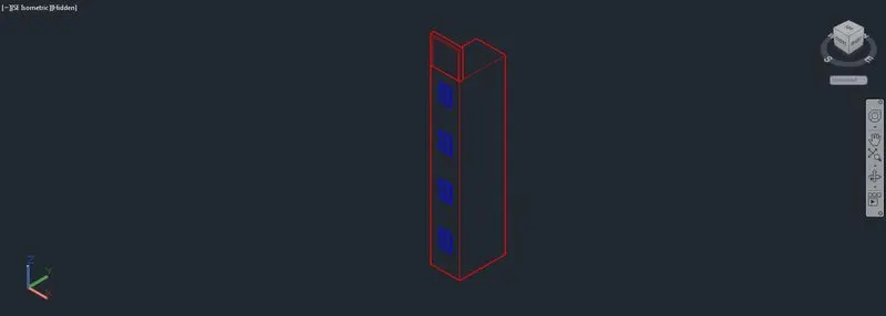
- After creating the elevation in top view the view is changed to 3D Isometic view then using the 3D rotate command the elevation is rotated in z axis .
- Then layers are created from the riboon as windows and walls and assigned to the figure.
- Further using extrude command the elevation figure is extruded to provide the width of the building and the 3d isometric view of the building is created.
Results: The given plan and elevation is created and presented in 3D Isometric view sucessfully and various views are also provided with assigned layers.
3. Create the ismoteric 3d view of a stair with railing as shown in the plan and elevation. Assume the size of the balustrades and the hand rails.
Aim: To Create the ismoteric 3d view of a stair with railing as shown in the plan and elevation.
Introduction: The given figure consists of plan and side elevation of the stairs. The stair rise and tread are given as 6" and 12" respectively. The size of handrails are assumed. The diagram is drawn in imperial system as the given figure is in feet and inches.
Steps:
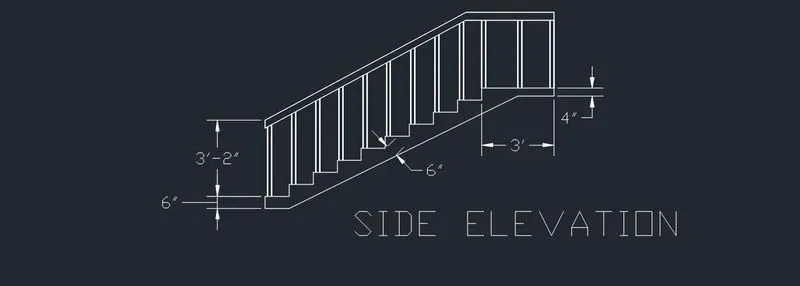
- Initially the view is fixed in front and the ucs is changed to xy plane by using ucs command
- Then using the line command with rise and tread of 6" and 12" respectively the stairs are drawn.
- Then the balustrades are provided, using line command a line is drawn 2'-6" is drawn and a offset of 3" is done using offset command
- Then the balustrades are copied and placed in every step of the stair.
- Then for providing handrails a line is drawn from 1st step to height of 3'-2" and the line is inclined and drawn in the direction of the stair with the angle of stairs provided.
- Then the balustrades are extened to the hand rails by using extend command.
- After defining the dimension and text style, dimensions are marked using dimlinear and dimcontiue command and texts are provided as per the requirement using mtext command.
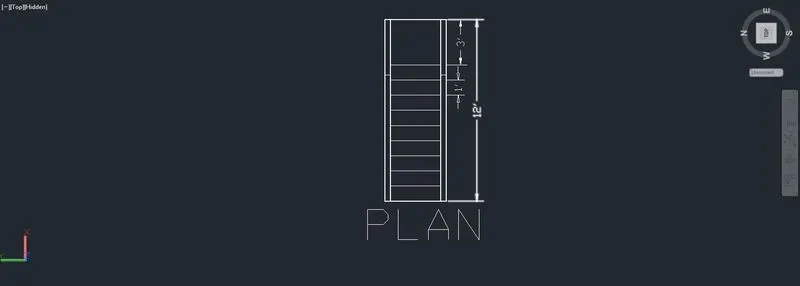
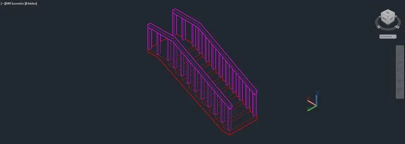
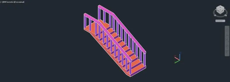
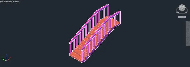
- Then the view is restored to default isometric view and using the region command the whole figure is joined
- Then the stairs are subjected to extrude using the extrude command and a width of 4' is given
- The balustrades and handrails are also extruded to a width of 6" and it is copied and placed in other side of the staircase.
- Layers are defined and assigned to the figure from layer properties in ribbon
- Then different view of the staircase are provided.
Results: The given stair with handrails are created sucessfully and different conceptual and hidden views are provided sucessfully.
4. Create the 3D view of a Wall with spread footing . Create the Door opening only. Assume the size of the parpaet and the coping. See the plans and elevation for the details. Also, create a rendered view of the model with materials as of your choice.
Aim: To Create the 3D view of a Wall with spread footing and also to create a rendered view of the model with materials assigned.
Introduction: The given model is a figure of a wall with the spread footing and a section of the model is also given. The materials are also assigned to the created figure from material browser and rendering of the same is done. The thickess of the wall is assumed as 230mm. The coping of the foundation is asuumed as 650,430 and 330 mm respectively. The given drawing is drawn in metric system as the given figure is in mm.
Steps:

- The plan of the figure is created by drawing a rectangle of size 650 x 7500 using rectangle command and exploded using xplode command
- Further using the offset command at a distance of 110 on either sides is done following that again offset is done to the offsetted lines at a distance of on either side
- Then a offset of 3300 on top and bottom sides of the plan to provide door opening.
- After defining the dimension and text style, dimensions are marked using dimlinear and dimcontiue command.

- For section diagram intially four rectangles are drawn of sizes 650 x 300,430 x 400, 330 x 400 and 230 x 600 and are placed on top of each other.
- Then using the line a line is drawn to 3300 and a width oof 230 mm is provided and closed at the other side of the rectangle
- Then at height of 2100 from the ground level sunshade is provided.
- Using the hatch command hatch is provided and the hatch scale is fixed as per the requirement.
- Then dimensions are marked using the dimlinear command .
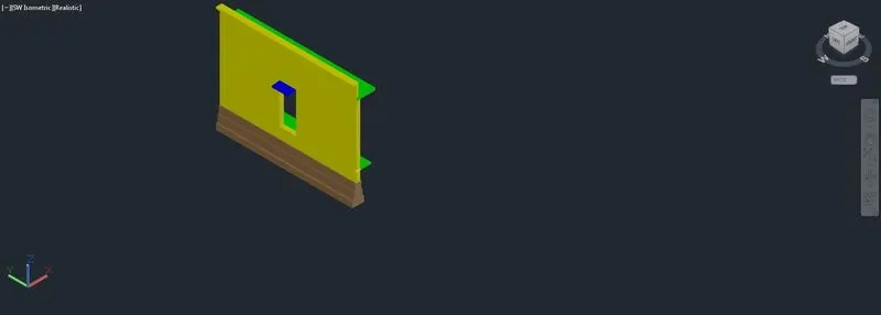

- Then the view is restored to default isometric view and extrude command is used before converting it to a region by region command and the extrusion is done to a distance of 7500
- Then at the middle at 3300 distance from either sides with the width of 900 door is provided and it is extruded to a distance of 230mm using extrude command and using subtract command it is subtracted from the wall face.
- Sunshade is provided at the top of the door with the width of 900mm
- Then layers are defined in layer properties from ribbon and are assigned to the drawing
- Finally realistic and conceptual views of the diagram created are provided.
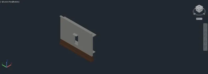
- Then to provide materials to the created drawing option called material browser is used from the visulize tab from the ribbon
- In the material browser the materials for foundation and walls are selected and appearance of materials such as colour are edited as per the requirement and are assigned to the generic table.
- Then the components are selected and the materials added by selecting 'assign to selection' option from the material browser
- After assigning the materials the realistic 3d view is provided
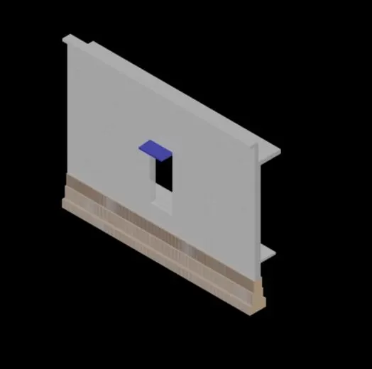
- Finally for rendering the created figure initially camera and lights are provided
- For providing camera a circle is created and extruded at the view needed and camera is placed on top of the created circle by selecting camera option from visualize tab in ribbon
- Then lights are provided at top 90deg and in top of the camera
- The lights are provided light option in visualize tab from ribbon. In this case point lights are provided and intensity of the light is fixed as per the requirement from the properties panel of the light
- Then using the render region command the created figure is rendered and saved as jpeg image.
Results: The given plan and section of the wall created sucessfully and the materials are assigned as per the requirement and conceptual and realistic views are provided further, the created figure is rendered and the rendered image is provided sucessfully.