Creating 3D Isometric view of various structural elements in AutoCAD
1. Create a 3D Isometric View of the building with plan and elevation given.
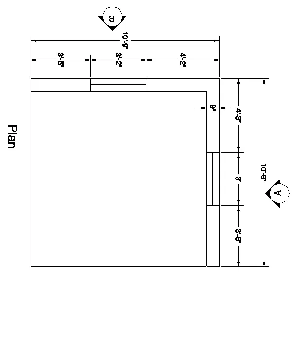
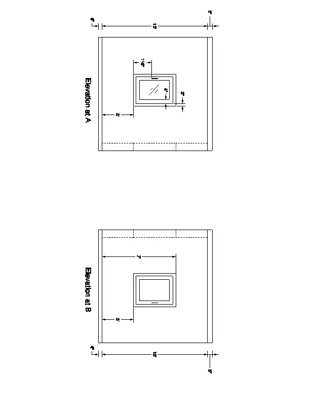
AIM:
To Create an isometric view of the wall at the required dimension.
INTRODUCTION:
- Plans and Sections are different types of drawings used by architects to graphically represent a building design
- A plan drawing is a drawing on a horizontal plane showing a view from above.
- An Elevation drawing is drawn on a vertical plane showing a vertical depiction.
- A section drawing is also a vertical depiction but one that cuts through space showing what lies within.
COMMAND ARE USED:
- Line command
- Rectangle command
- UCS command
- Dimlinear command
- Region command
- Extrude command
- Substract command
- Units command
- Dimstyle command
- 3Dface command
- Explode command
- Move command
- Copy command
- Rendering command
- Layer command
PROCEDURE:
- First we set an unit as per the engineering and dimenion of inch have choosed
- Next we et limmax and limit spec @0,0 and 100,100
- Then z enter and a enter
- Then we choose 2d wire frame
- To draw the outer line of the plan
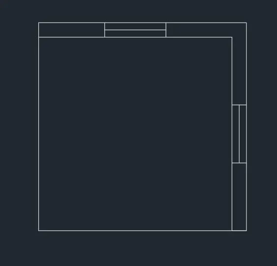
To create the window over the dimension of the 3' and the get the offset of the frame at the 3"
To create the dimension of the required dimension
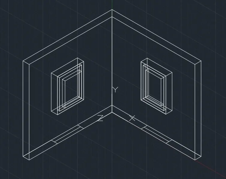
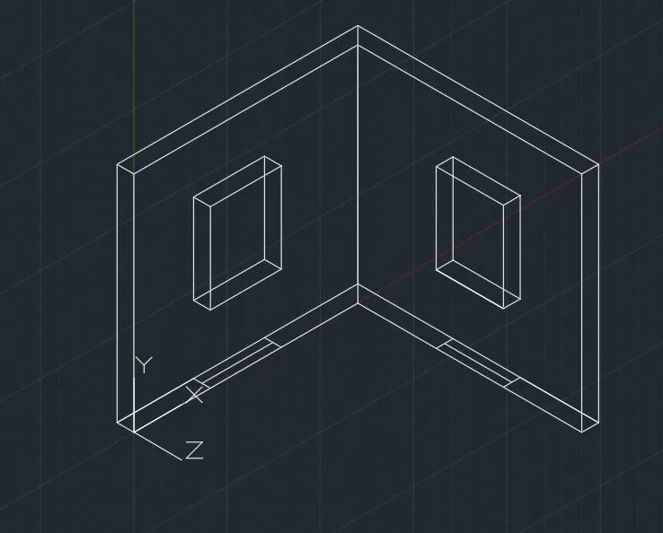
To create the drawing over the 3d drawing and extrude the drawing
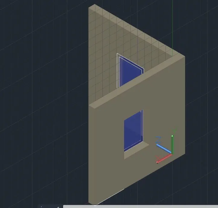
To change the view of the drawing
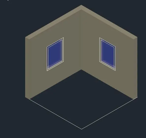
RESULT:
Finally we get in to the 3d wall in the specific dimension
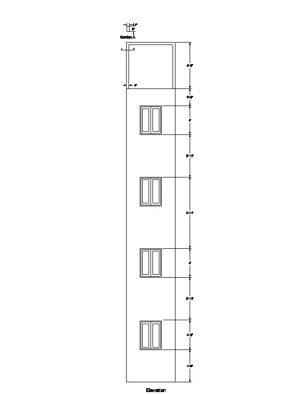
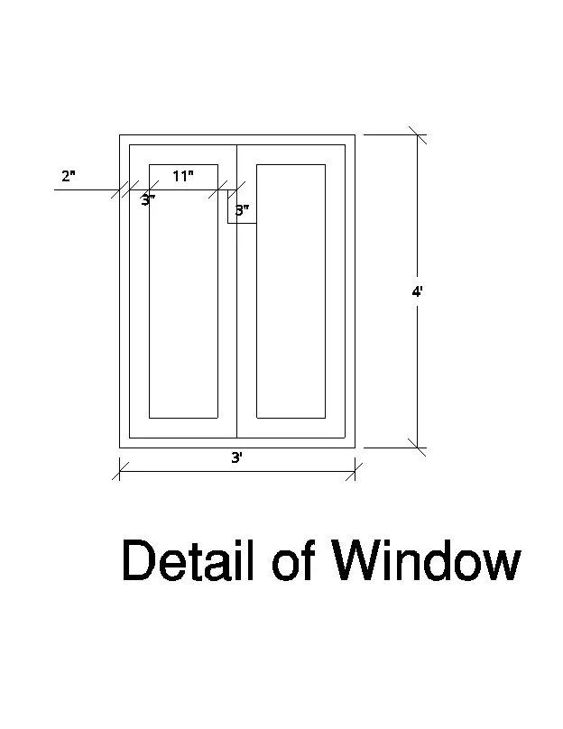
2. Create the 3D View of the Building Façade as given in the plan and elevation. Also, see the detail of the window.
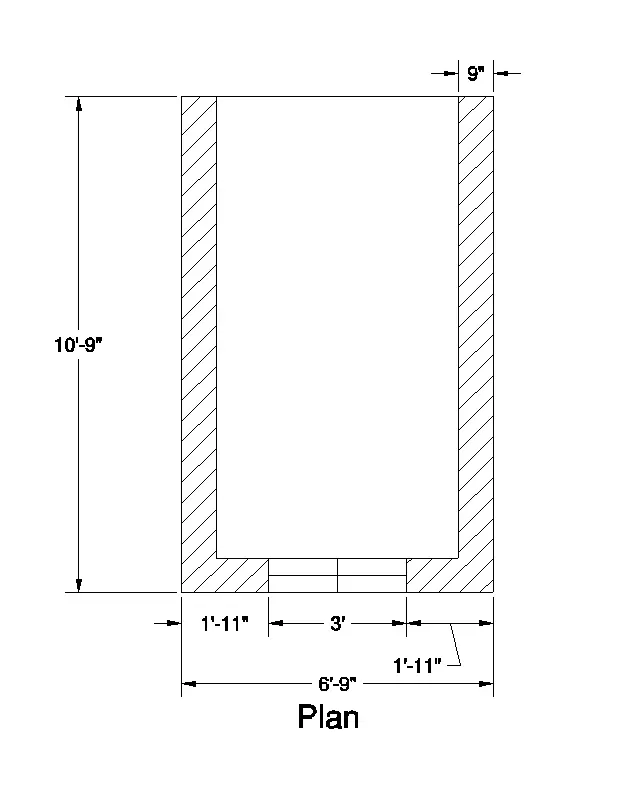
AIM:
To Create an elevation of the house and deatil of the window
COMMAND ARE USED:
- Line command
- Rectangle command
- UCS command
- Dimlinear command
- Region command
- Extrude command
- Substract command
- Units command
- Dimstyle command
- 3Dface command
- Explode command
- Move command
- Copy command
- Rendering command
PROCEDURE:
- First we set an unit as per the engineering and dimenion of inch have choosed
- Next we et limmax and limit spec @0,0 and 100,100
- Then z enter and a enter
- Then we choose 2d wire frame
- To create the outer boundary line 10'9" and 6'9"
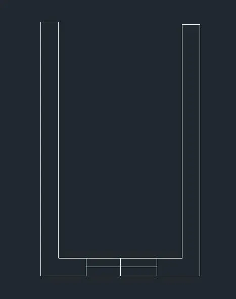
- Hatch the wall using hatch command
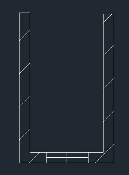
- To Select the South west isometric view and extrude the building to the required height
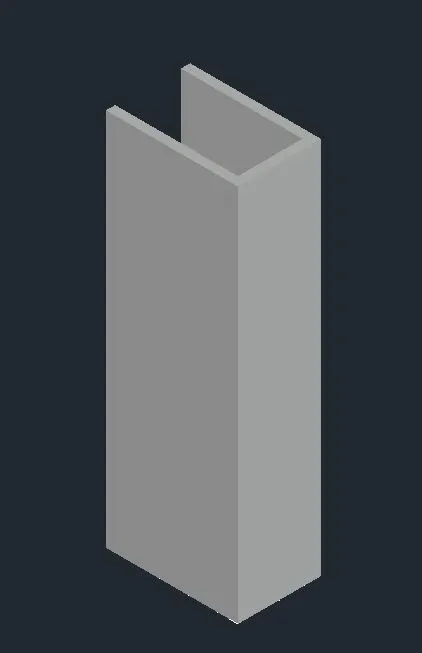
- Next we draw the window 3' and 4'
- To adjust the ucs and take offset command using at the 3" at the distance of 11"
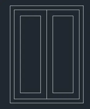
To copy the window and where they required paste the window
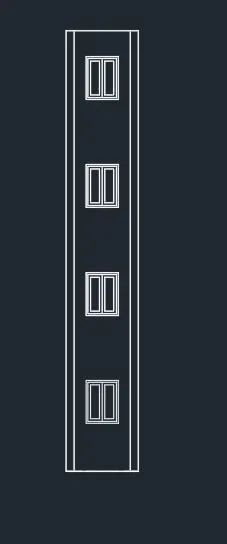
To extrude the wall at the specific dimension
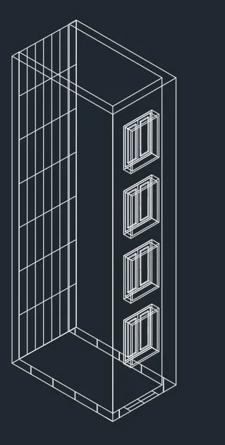
To create the floor and the the parapet wall
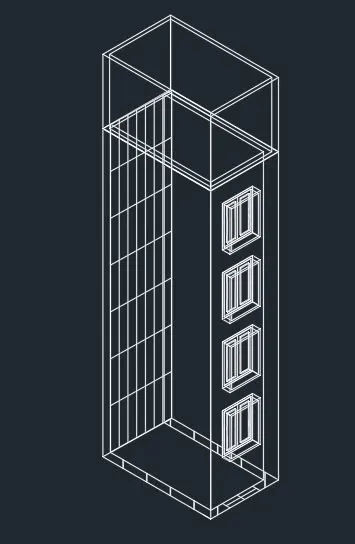
To change the 2d wireframe to the shaded command
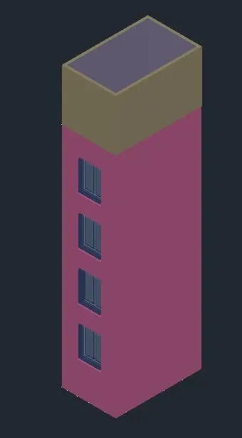
To create the color to the layer of the elevation
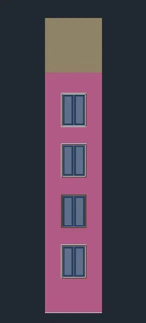
RESULT:
Finally we get the elevation of the house
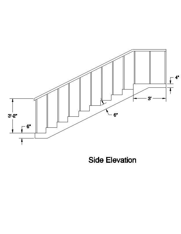
3. Create the ismoteric 3d view of a stair with railing as shown in the plan and elevation. Assume the size of the balustrades and the hand rails.
AIM:
To Create a 3D staircase and the elevation of the dimension
COMMAND ARE USED:
- Line command
- Rectangle command
- UCS command
- Dimlinear command
- Region command
- Extrude command
- Substract command
- Units command
- Dimstyle command
- 3Dface command
- Explode command
- Move command
- Copy command
PROCEDURE:
- First we set an unit as per the engineering and dimenion of inch have choosed
- Next we et limmax and limit spec @0,0 and 100,100
- Then z enter and a enter
- Then we choose 2d wire frame
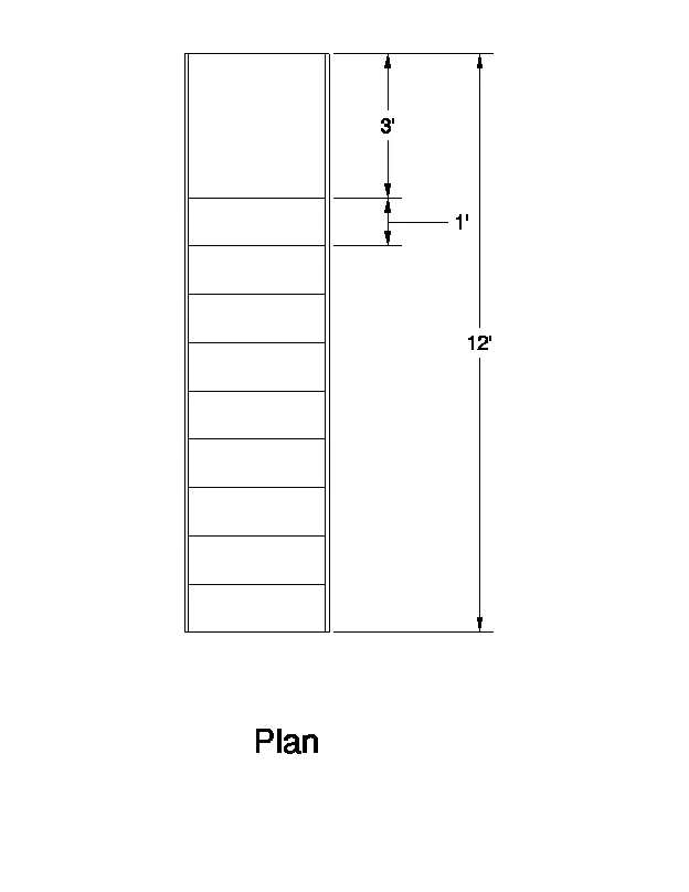
- To create the outer line 12' and 2'6"
- The riser6" and treat 1' are respetively
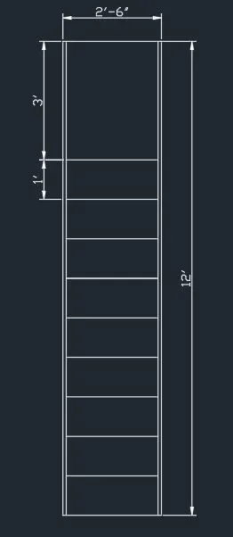
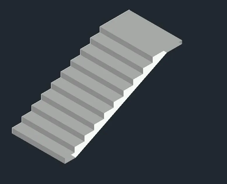
To extrude the staircase
To create the circle and extrude the 2' circle to the cylinder
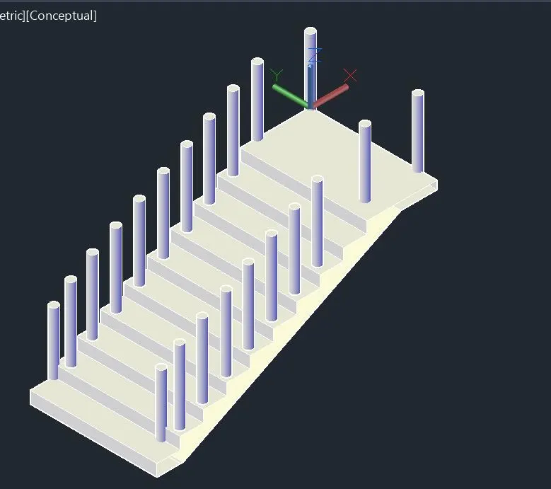
To connect the handrail in the staircase
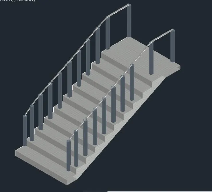
To change the 2d wireframe to the shaded
RESULT:
Finally we get the staircase elevation
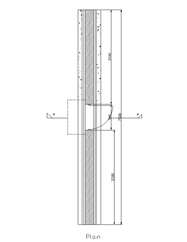
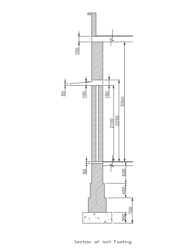
4. Create the 3D view of a Wall with spread footing . Create the Door opening only. Assume the size of the parpaet and the coping. See the plans and elevation for the details. Also, create a rendered view of the model with materials as of your choice.
AIM:
To Create a 3D wall with footing
COMMAND ARE USED:
- Line command
- Rectangle command
- UCS command
- Dimlinear command
- Region command
- Extrude command
- Substract command
- Units command
- Dimstyle command
- 3Dface command
- Explode command
- Move command
- Copy command
- Hatch command
PROCEDURE:
- First we set an unit as per the engineering and dimenion of mm have choosed
- Next we et limmax and limit spec @0,0 and 100,100
- Then z enter and a enter
- Then we choose 2d wire frame
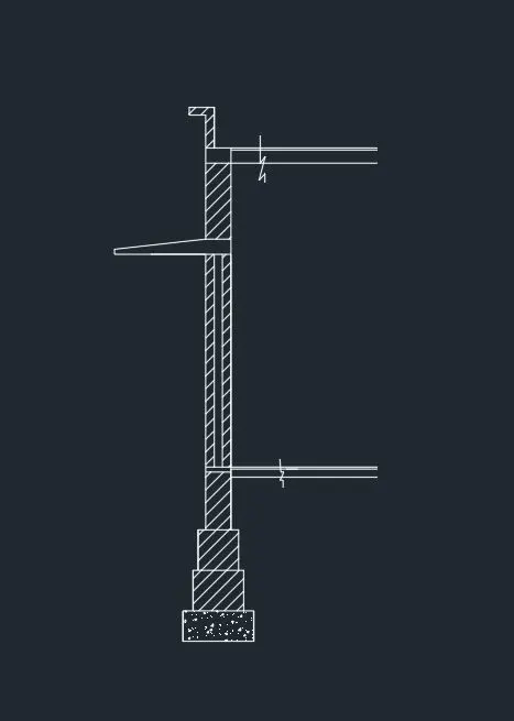
- The plan of the wall with the spread footing is drawn using the datas given in the question in top view
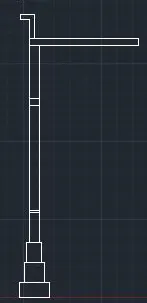
- Next take the front view, and draw the section of wall footing.
- Hatch the areas required with appropreate hatches
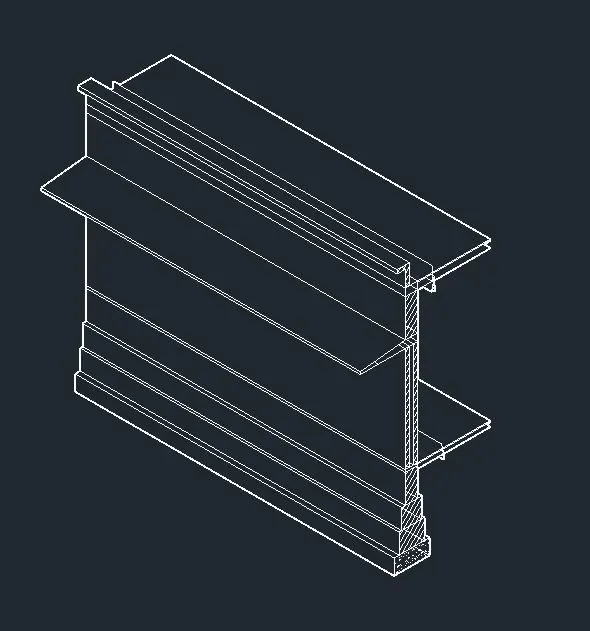
- Take the south west isometric view
- Next extrude the full drawing, with required height
- Next to the material browser and select the apporiprate the wall
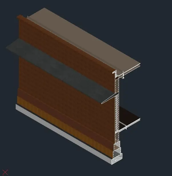
RESULT:
Finally we draw the wall with the spreaded footing