Creating 3D Isometric view of various structural elements in AutoCAD
1.AIM-:Creating the 3D isometric view of plan and sections given in the figures.
Drafting of Plan:-
Procedure:-
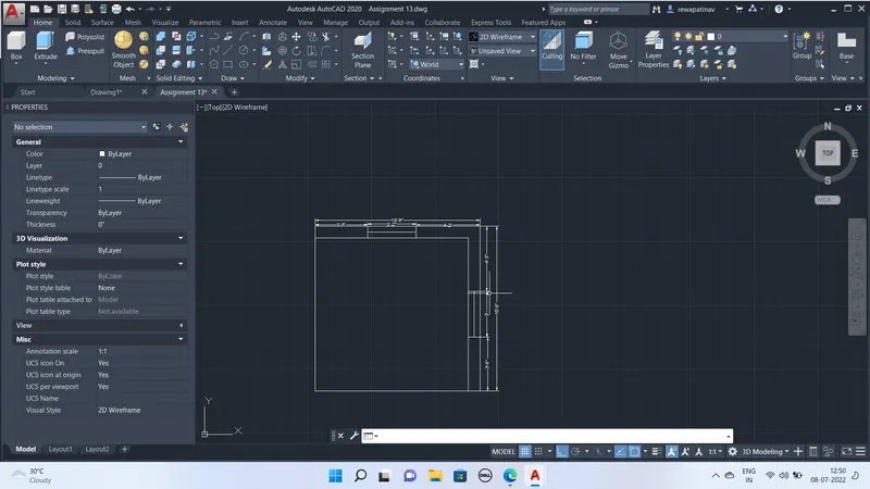
- Open AutoCAD , Command UN @ Engineering Inches
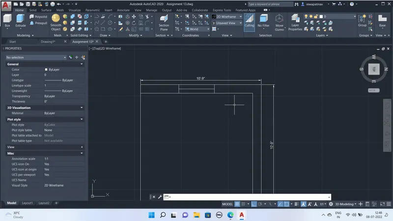
- Line command Line of length 10'9" Than offset at 9" In both X&Y directions.
- Window created with given distances.
3D Modelling Procedure
Boundray Command Pick the internal point of walls and created the region
EXT command used with given height of walls 10' exepting place of windows.
Floor is created of 4" thickeness by extruding of the rectangle.
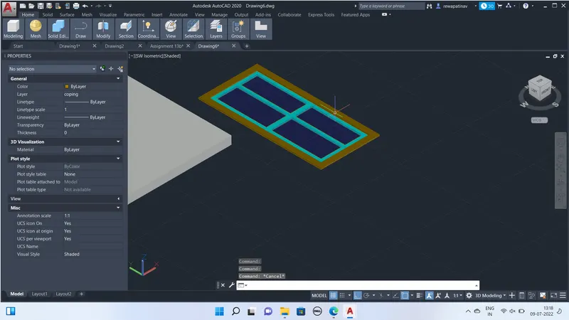
Window is created of size 3'x4'
Making offsest of rectangle at 3" & 4 inches inner side 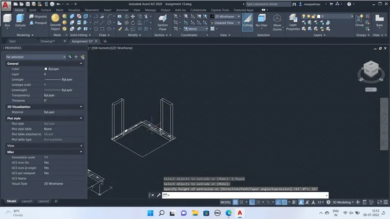
 SDDSD
SDDSD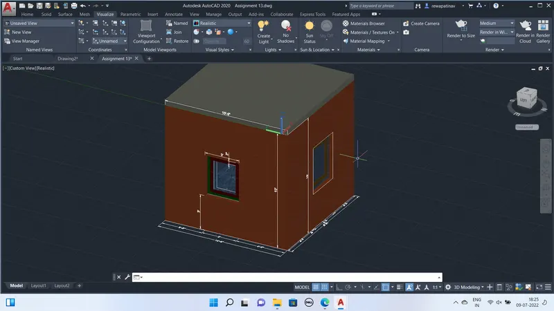
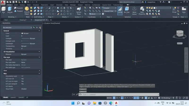
- crearion of wall opening by drawing rectangle at bottom and extrude at height of 3'
- than rectangle at the top of walls and than extrude downword of-4'
- Window placed by command used 3Drotate and move at the perticular opening
- Material assigned as glass and the floor as granite using material browser
2.AIM:-
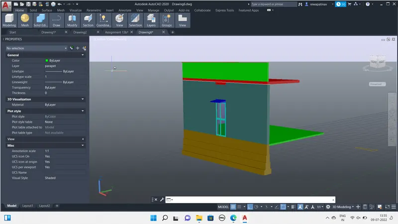
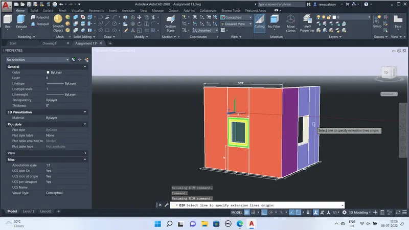
Creating 3D view of the building facade as given in the plan .
Drating of plan
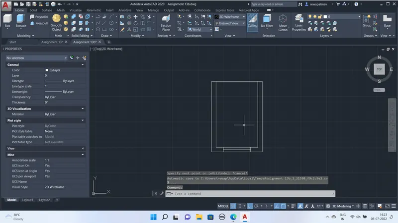
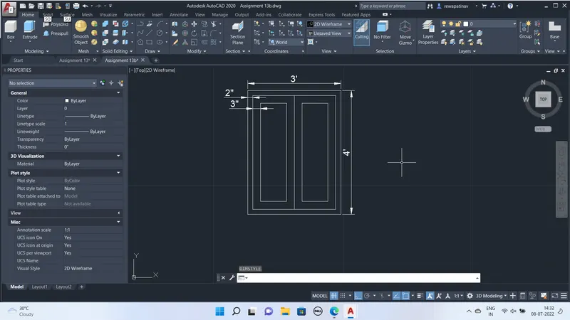
Creation of window
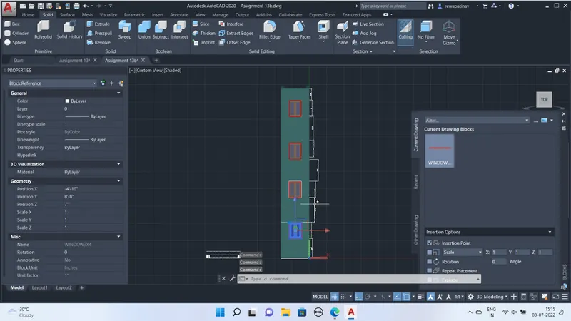
- Than Extruding the wall region at the specified heights given in the figure
- Than UCS placed at the front face and rectangle of window size 3;x4' drawn and placed at the window locations by coping
- and then extrude all the rectangles indside and than substract the rectangle from the wall to create the duct for window
- than window rotated and placed at the suitable locaions.
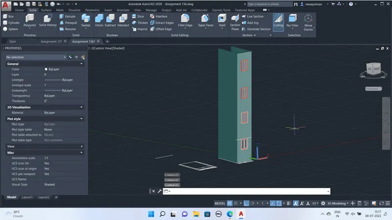
e 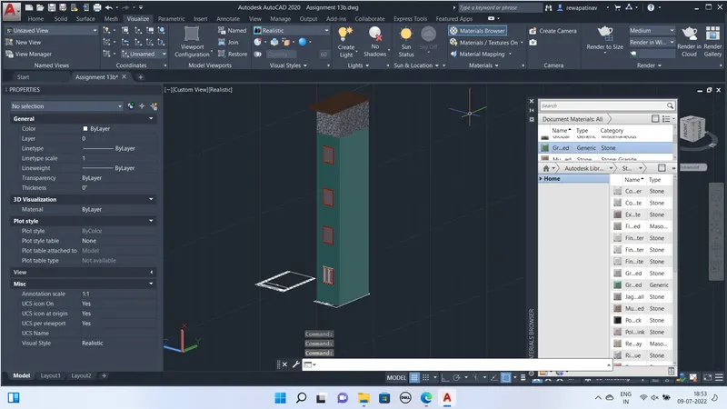
3.AIM-:Creating the isometric view of the stairs with railing by assuming the blauster of 1" dia and railing of 2" dia
DrAFTING 2d PLAN :-
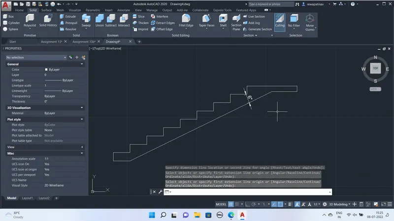
After creation of 2D plan than 3d rotate the all segment with 90 degree
Extrude with width of 3 feet see the snap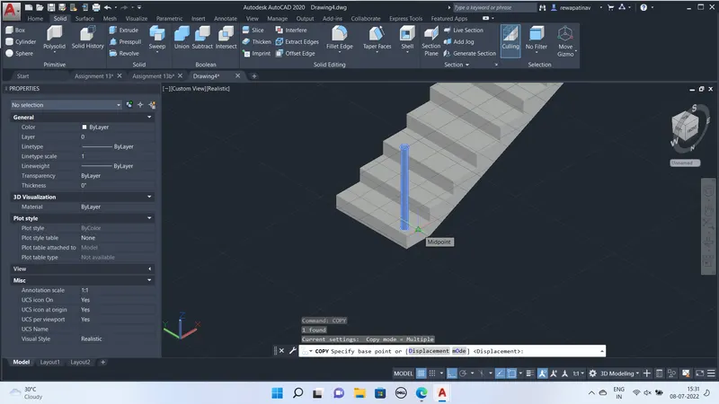
for creation of blauster circle drawn at th first step than extrude at height of 3'
copy the bluster at all steps by Taking corner of step as basepoint
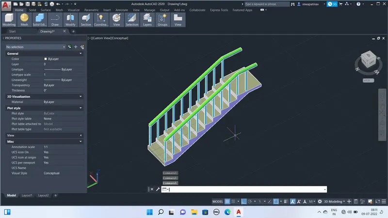
Than plyline drawn to connect upper centers of the blauster and than Sweep a circle over it of radius 1"
Same procedure on other side is done,
3.AIM
Creation of 3D view of wall with the spread footing
Creationof section of the wall First
Assuming the wall thickness 200
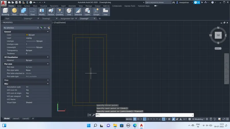
drafting of door panel of size 900x2100mm