Creating 3D Isometric view of various structural elements in AutoCAD
1)
Aim :-
Create a 3D Isometric View of the building with plan and elevation given figure by using Auto CAD 3D Modelling.
Procedure :-
* Open the AutoCAD software.
* Startup(start from scratch) with default setting as imperial.
* Set the settings as 3D basis.
* Dimensions set as engineering.
* We can use the proper drafting tools to sketch the plan.
* We can use proper dimension techniques to dimensioning as per the figure.
* Set the setting as 3D Modelling.
* We can start the drafting in 3D Modelling as shown in the given figure.
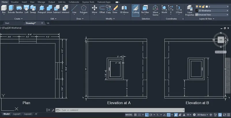
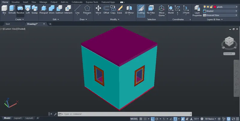
Result :-
Successfully create a 3D Isometric View of the building with plan and elevation given figure by using Auto CAD 3D Modelling.
2)
Aim :-
Create the 3D View of the Building Façade as given in the plan and elevation by using Auto CAD 3D Modelling.
Procedure :-
* Open the AutoCAD software.
* Startup(start from scratch) with default setting as imperial.
* Set the settings as 3D basis.
* Dimensions set as engineering.
* We can use the proper drafting tools to sketch the plan.
* We can use proper dimension techniques to dimensioning as per the figure.
* Set the setting as 3D Modelling.
* We can start the drafting in 3D Modelling as shown in the given figure.
* And also draw the window as shown in the given details.
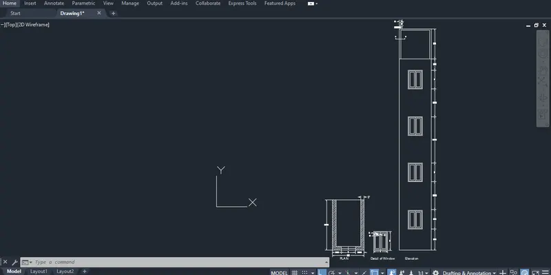
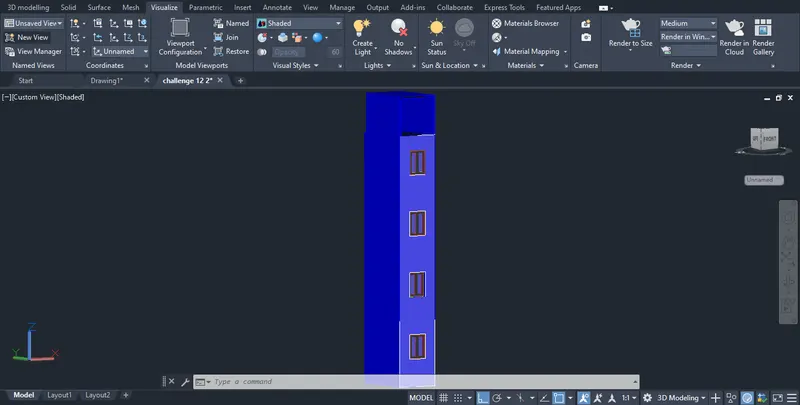
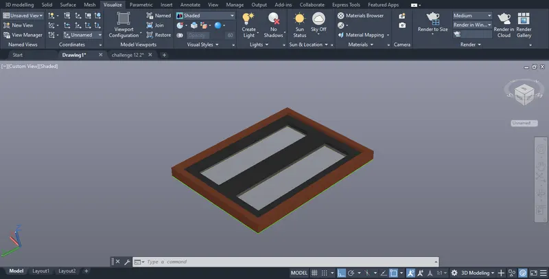
Result :-
Successfully create the 3D View of the Building Façade as given in the plan and elevation by using Auto CAD 3D Modelling.
3)
Aim :-
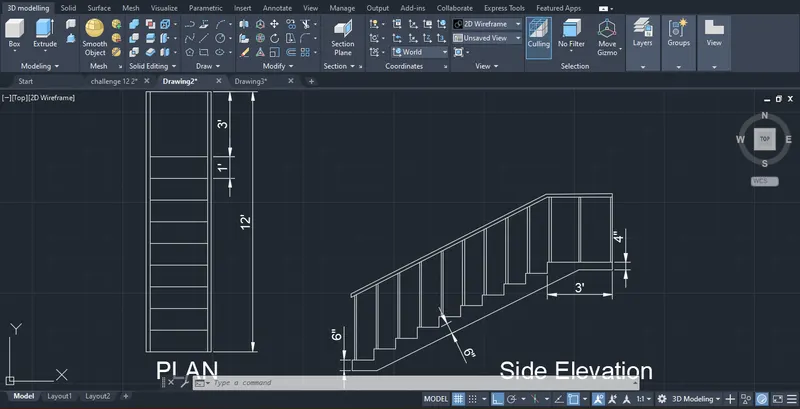
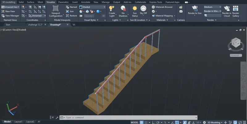
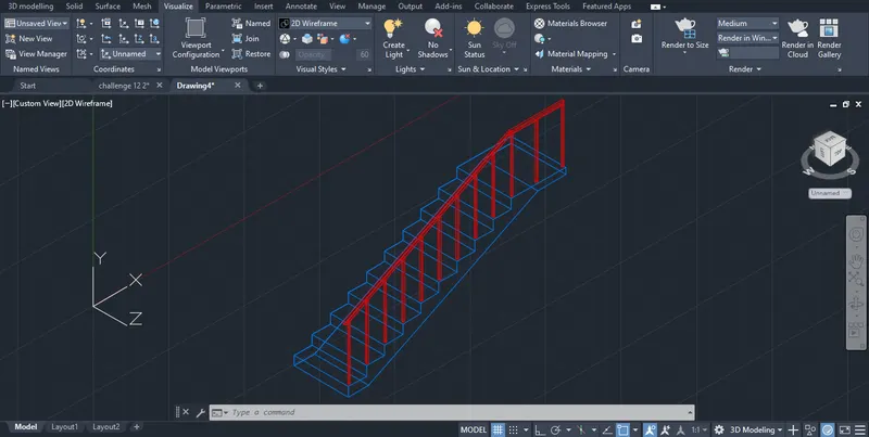
Create the ismoteric 3d view of a stair with railing as shown in the plan and elevation by using Auto CAD 3D Modelling.
Procedure :-
* Open the AutoCAD software.
* Startup(start from scratch) with default setting as imperial.
* Set the settings as 3D basis.
* Dimensions set as engineering.
* We can use the proper drafting tools to sketch the plan.
* We can use proper dimension techniques to dimensioning as per the figure.
* Set the setting as 3D Modelling.
* We can start the drafting in 3D Modelling as shown in the given figure.
* We can assume the size of the balustrades and the hand rails.
Result :-
Successfully create the ismoteric 3d view of a stair with railing as shown in the plan and elevation by using Auto CAD 3D Modelling.
4)
Aim :-
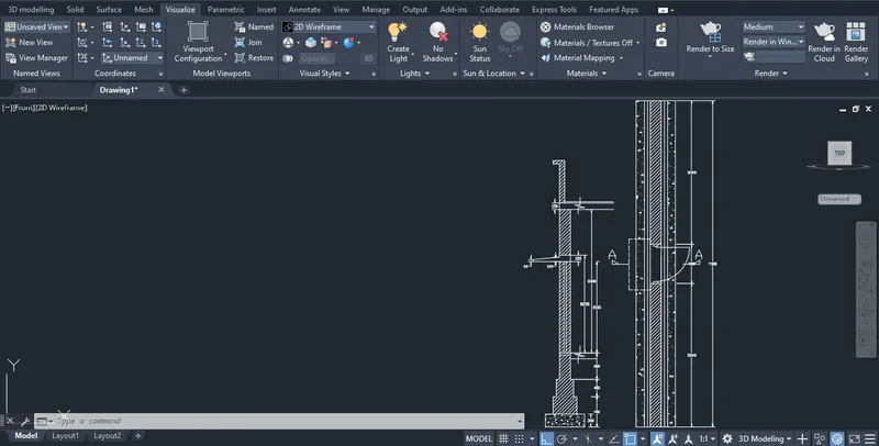
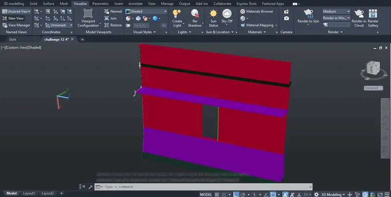
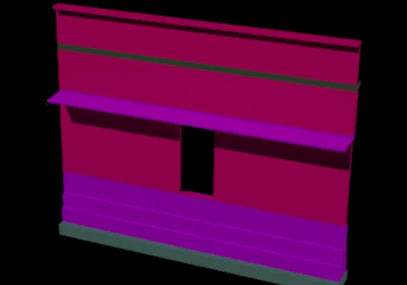
Create the 3D view of a Wall with spread footing and also the Door opening by using Auto CAD 3D Modelling.
Procedure :-
* Open the AutoCAD software.
* Startup(start from scratch) with default setting as imperial.
* Set the settings as 3D basis.*
* Dimensions set as engineering.
* We can use the proper drafting tools to sketch the plan.
* We can use proper dimension techniques to dimensioning as per the figure.
* Set the setting as 3D Modelling.
* We can start the drafting in 3D Modelling as shown in the given figure.
* We can assume the size of the parpaet and the coping.
* We see the plans and elevation for the details draw the figure.
Result :-
Successfully create the 3D view of a Wall with spread footing and also the Door opening by using Auto CAD 3D Modelling.