Creating 3D Isometric view of various structural elements in AutoCAD
1)
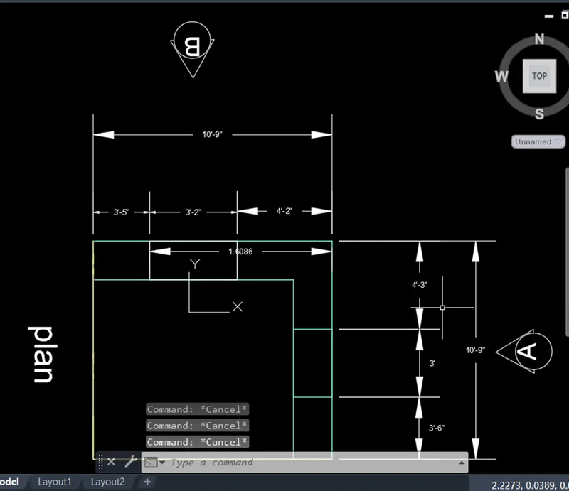
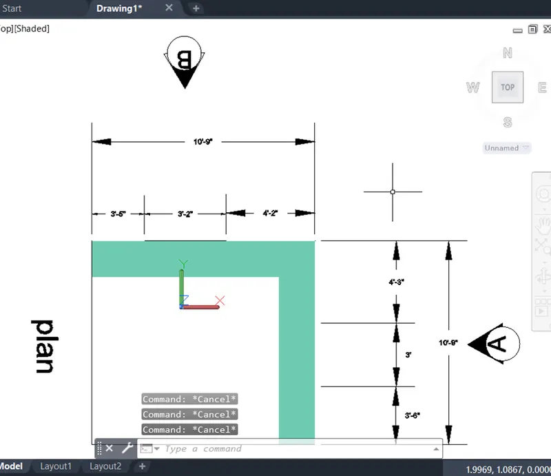
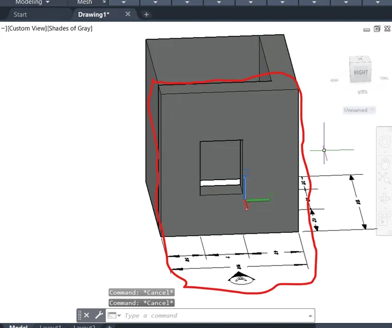
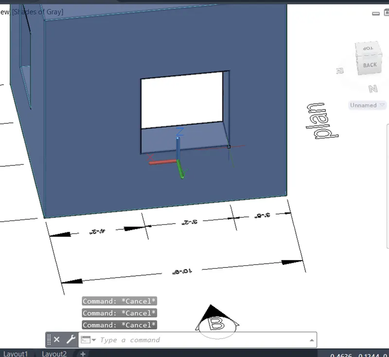
Aim: the main aim of these problem is to make tha plan and isometric views of the building with plan and elevation
Introduction: In this problem, i am gonna use draw tools,3d modeling tools such as extrude,subtract,trim etc,.
Procedure:
- starting with the new drawing sheet
- setting up the units as engineering
- setting the page to 3d modelling screen
- making the view as top for plan making
- using the draw tools such as line,rectangle,trim,etc,.plan should be done.
- after that using the 3d tools elevations are done
- finally dimensions are done
Result:
the results of the above procedure is as follows
2)
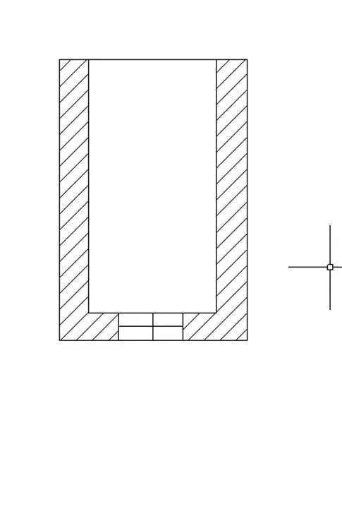
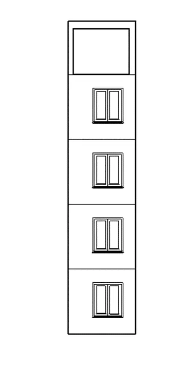
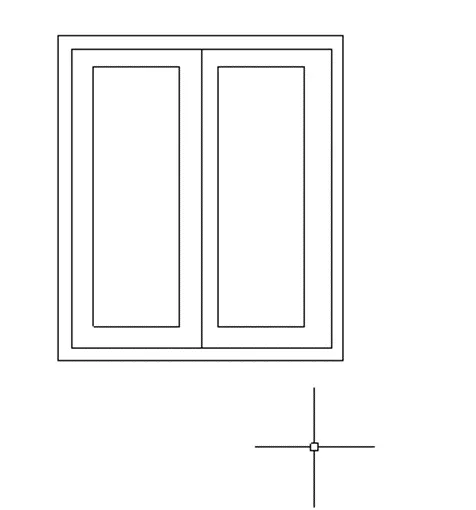
Aim: the main aim of these problem is to make tha plan and elevation of building facade.also window details.
Introduction: In this problem, i am gonna use draw tools,3d modeling tools such as extrude,subtract,trim etc,.
Procedure:
- starting with the new drawing sheet
- setting up the units as engineering
- setting the page to 3d modelling screen
- making the view as top for plan making
- using the draw tools such as line,rectangle,trim,etc,.plan should be done.
- after that using the 3d tools such as extrude,subtract.elevations are done
- finally dimensions are done
Result:
the results of the above procedure is as follows
3)
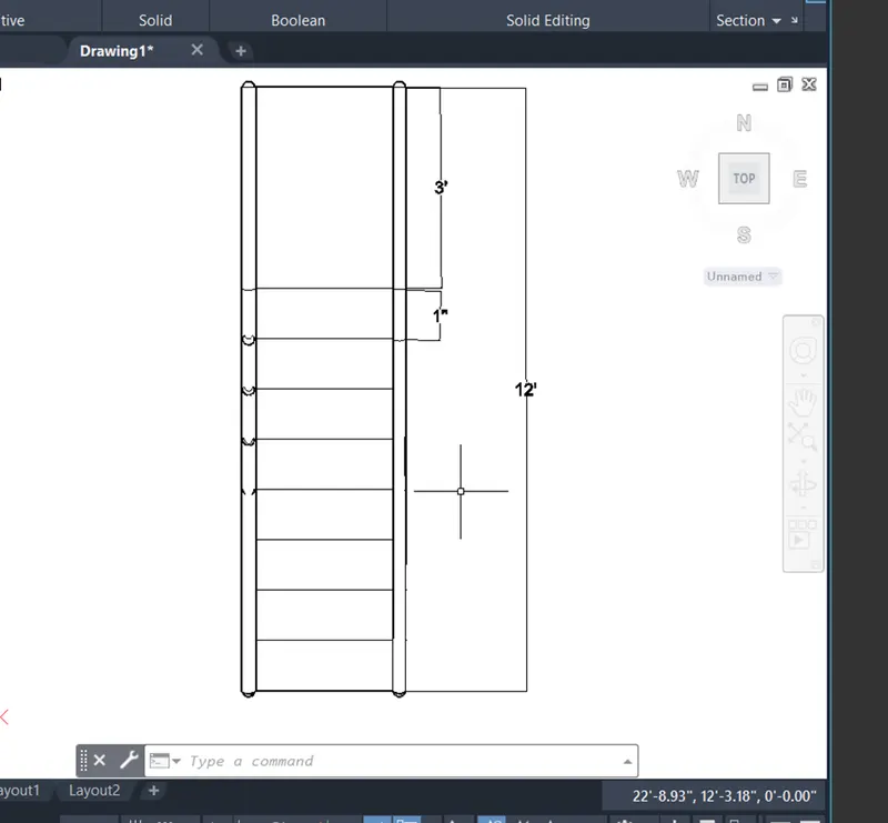
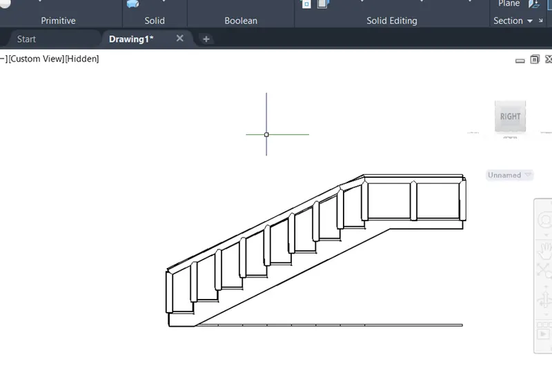
Aim: the main aim of these problem is to make tha plan and 3d view of the staircase with railing as given in the problem.
Introduction: In this problem, i am gonna use draw tools,modifying toolsn and 3d modeling tools such as extrude,subtract,trim,sweep,etc,.
Procedure:
- starting with the new drawing sheet
- setting up the units as engineering
- setting the page to 3d modelling screen
- making the view as top for plan making
- using the draw tools such as line,rectangle,trim,offset,copy,etc,.plan should be done.
- after that using the 3d tools,copy, elevations are done
- finally dimensions are done
Result:
the results of the above procedure is as follows
4)
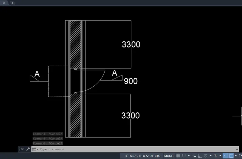
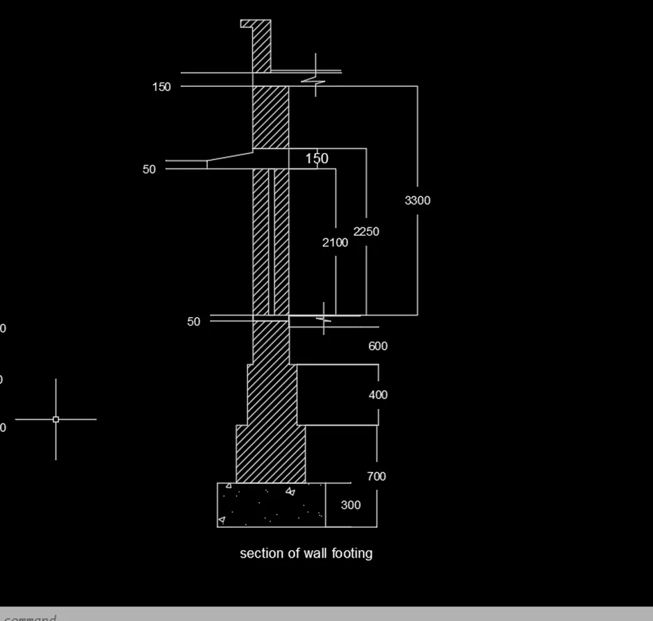
Aim: the main aim of these problem is to make tha plan and elevation of the wall at section A-A as given in the problem
Introduction: In this problem, i am gonna use draw tools,modifying tools and 3d modelling tools such as extrude,copy,etc.
Procedure:
- starting with the new drawing sheet
- setting up the units as decimals
- setting the page to 3d modelling screen
- making the view as top for plan making
- using the draw tools such as line,rectangle,trim,offset,copy,etc,.plan should be done.
- after that using the 3d tools,copy, elevations are done
- finally dimensions are done
Result:
the results of the above procedure is as follows