Creating 3D Isometric view of various structural elements in AutoCAD
AIM - CREATE A 3D ISOMETRIC VIEW OF THE BUILDING WITH PLAN AND ELEVATION GIVEN.
ANS -
1. TOP VIEW OF THE OBJECT -
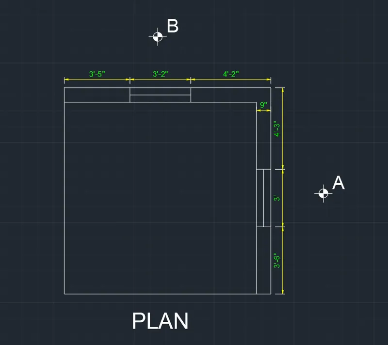
PROCEDURE -
PLAN - For creating plan taking line tool and create 3'5" x direction and 3'2" 4'2" after that create 4'3" in -y direction and 3' , 3'6" and create 10'9" in -x direction and close to the boundry.
OFFSET - Taking offset 9" from two side of the object as shown in the picture.
window - create a window by taking a line command in top portion create 3'6"x 9" window and side portion create 3'x9" window
DIMENSION - Using dimension in feetand inches for the object and changing its color by modiffied.
TEXT - using multiline text for the object
ANNOTATION - USING TEMPLATE for A and B for the object.
ISOMETRIC VIEW -
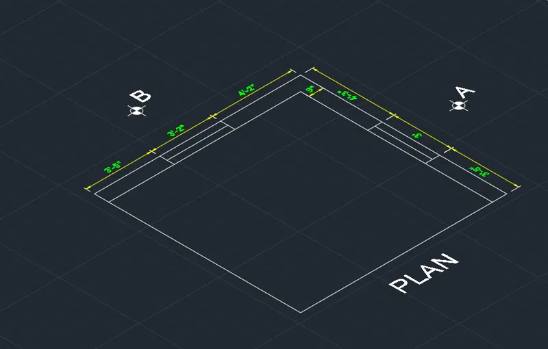
ISOMETRIC VIEW OF THE OBJECT
ELEVATIO AT A - TOP VEIW OF THE OBJECT
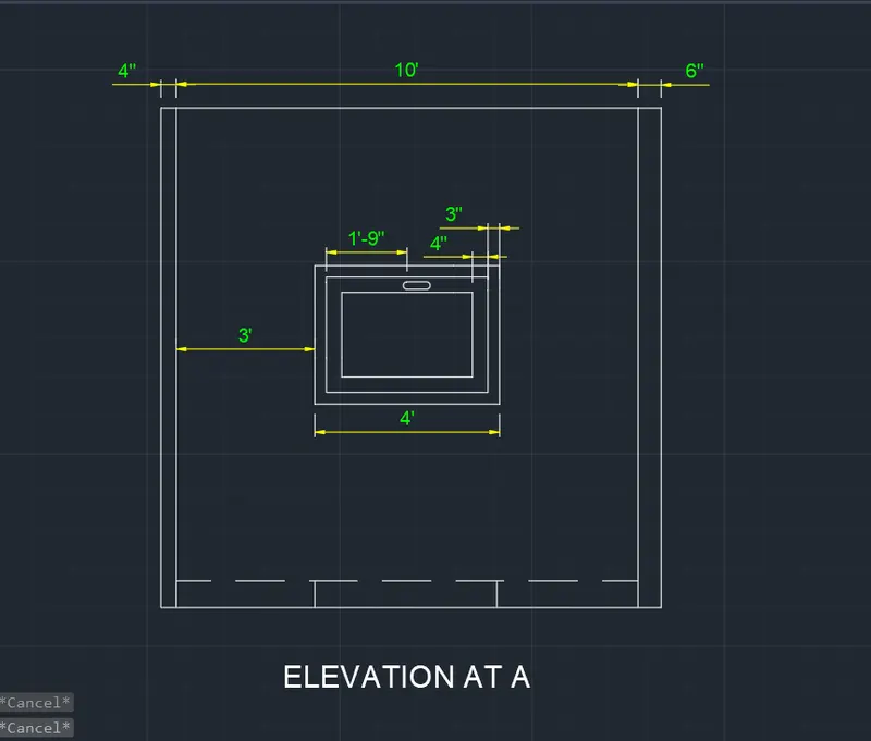
PROCEDURE -
ELEVATION - To create elevation taking line tool and create a line ix x direction continousely 4" , 10' , 6" in -y direction create -10' and also create 10' in -x direction and close to the boundry.
WINDOW - To create window taking rectangle and create 4'x3' rectangle and providing offset 3" and 4" continousely inside the window 1'9" distance provide a small lock inside the window
DIMENSION - Using dimension in feetand inches for the object and changing its color by modiffied.
TEXT - using multiline text for the object
ISOMETRIC VIEW OF ELEVATION - A
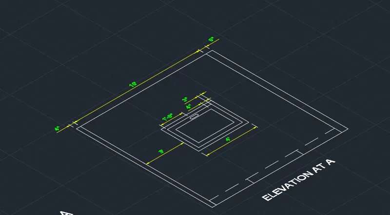
ISOMETRIC VIEW OF OBJECT
ELEVATION AT - B
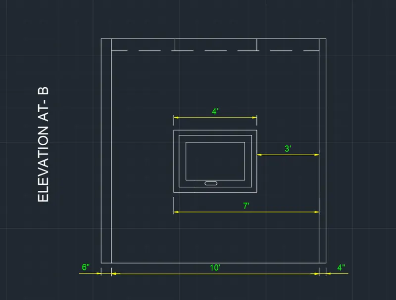
PROCEDURE -
ELEVATION - To create elevation taking line tool and create a line ix x direction continousely 4" , 10' , 6" in -y direction create -10' and also create 10' in -x direction and close to the boundry.
WINDOW - To create window taking rectangle and create 4'x3' rectangle and providing offset 3" and 4" continousely inside the window 1'9" distance provide a small lock inside the window
DIMENSION - Using dimension in feet and inches for the object and changing its color by modiffied.
TEXT - using multiline text for the object
RESULT -
ISOMETRIC VEIW OF ELEVATION - B
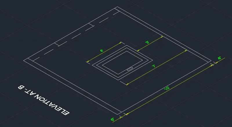
ISOMETRIC VIEW OF OBJECT
AIM - CREATE A 3D VIEW OF THE BUILDING FACADE AS GIVEN IN THE PLAN AND THE ELEVATION ALSO SHOW THE DETAILS OF THE WINDOW.
ANS -
TOP ELEVATION OF THE PLAN
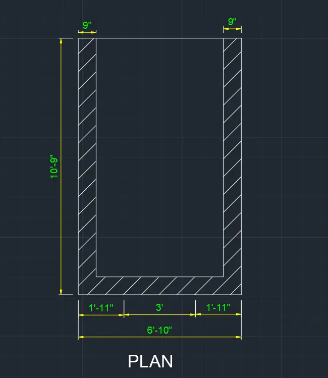
PROCEDURE -
PLAN - Taking line tool and create 10'9" line in -y direction and crete 1'11", 3' , 1'11" in x - direction crete a 10'9" in y direction
OFFSET - Taking offset 9" in both direction and taking its bottom side also.
HATCHING - for hatching use ANSI31 and modifie according to required.
DIMENSION - Using dimension in feet and inches for the object and changing its color by modiffied.
TEXT - using multiline text for the object
ISOMETRIXC VIEW OF THE PLAN -
RESULT -
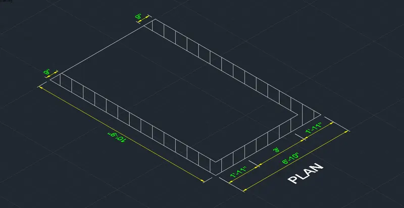
ISOMETRIC VIEW OF OBJECT
SECTION A ELEVTION -
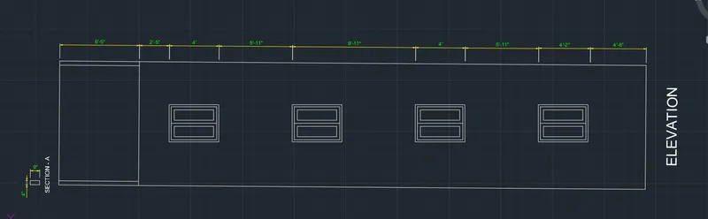
PROCEDURE -
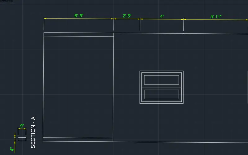
SECTION - A - for creating section a taking line tool 10' line in x direction after that continousely taking 6'5" , 2'5" , 4' 5'11"
and continousely create 9'11" , 4' , 5'11" , 4'2" , 4'6" after that taking 10' line in bottom side and close it to the start point.
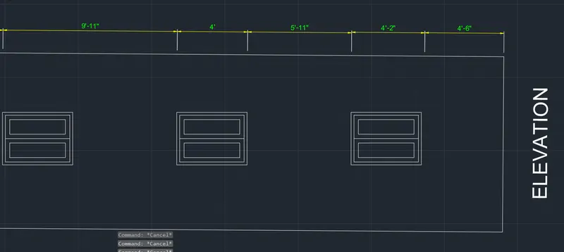
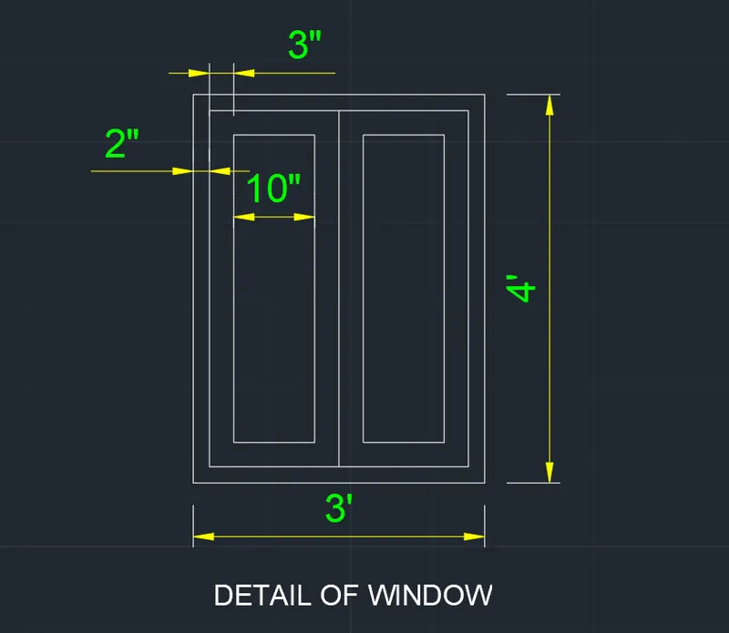
window - for creating window taking rectangle having 3'x4' size and ofsseting continoue for 2" and 3" and create a center line inside the window and found 10"x 3'2" window
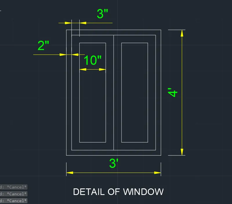
DIMENSION - Using dimension in feet and inches for the object and changing its color by modiffied.
TEXT - using multiline text for the object
RESULT -
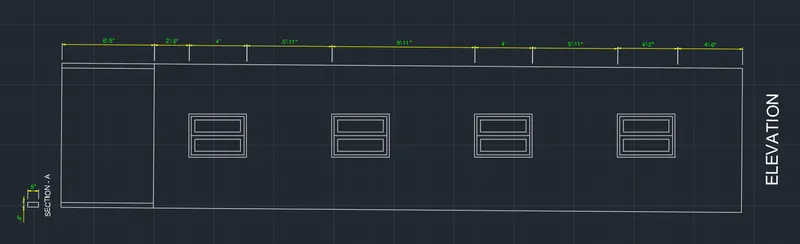
ISOMETRIC VIEW -
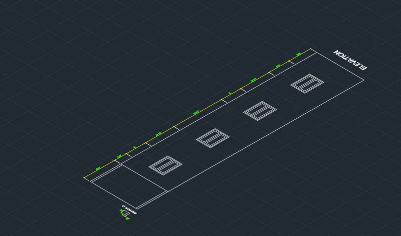
ISOMETRIC VIEW OF ELEVATION
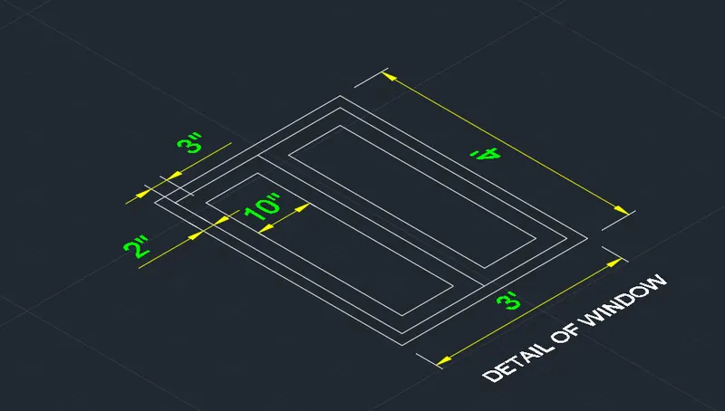
ISOMETRIC VIEW OF WINDOW
AIM - CREATE A ISOMETRIC 3D VIEW OF A STAIR WITH RAILLING AS SHOWN IN THE PLAN AND ELEVATION .
ANS -
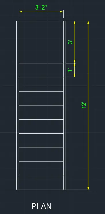
PROCEDURE -
PLAN OF STAIRCASE - For creating a plan of stair case taking line tool and create a line having 3'2" leangth in x direction and tasking line 3' in -y direction and continue create 9' line in -y direction. after that close to the end point of the line.
offset - for showing a steps to the plan create a line in top side of bottom of the 3' and and create a horizontal line and offseting it by 1' in 10 times. for railling taking 2' offset for both side.
DIMENSION - Using dimension in feet and inches for the object and changing its color by modiffied.
TEXT - using multiline text for the object.
RESULT - ISOMETRIC VIEW OF STAIRCASE
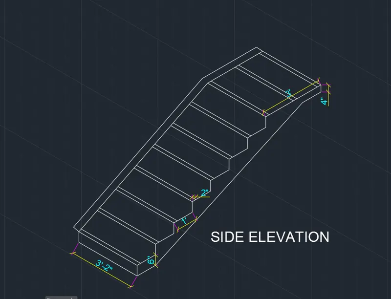
PROCEDURE -
STAIRCASE - FOR making staircase on the isometric left and taking a line tool and create 6" rise and 1' trade by moving cursor up and down creating 10 steps after that cretae a 3' landing in top of the stair and provide 3'2" leangth to the stair and end a line its start point.
offset - in the steps provide 2" offset for showing steps. for railing also taking 2" offset it mension in the object.
DIMENSION - Using dimension in feet and inches for the object and changing its color by modiffied.
TEXT - using multiline text for the object.
AIM - CREATE A 3D VIEW OF THE WALL WITH SPREAD FOOTING CREATE THE DOOR OPENING ONLY ASSUME THE SIZE OF PARAPET.
ANS - top view of object.
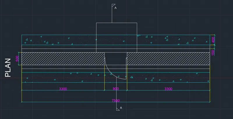
PROCEDURE -
LINE - FOR create a 3d view of wall taking line tool and create 7500 mm horizontal line.
offset - after creating line provide a offset of 400 mm after that 150mm two times continousely 500mm for wall 150mm , 150mm
HATCHING - for providing haching create 3300mmx500mm rectangle in both side of the wall area. and hatching by ANSI31.
also hatching its top portiob by sand.
DOOR - IN middle side of the wall having space 900mm to create a door in the middle portion create a 20x500 mm in both side and create a straight line after that taking a circle tool and create a circle from its start point and trim it according to its size.
dimension - to provide dimension use decimal unit and modifie changing text color is pink and create extension line is yellow provide dimension line is cyan color.
TEXT - using multiline text for the object.
isometric view of object -
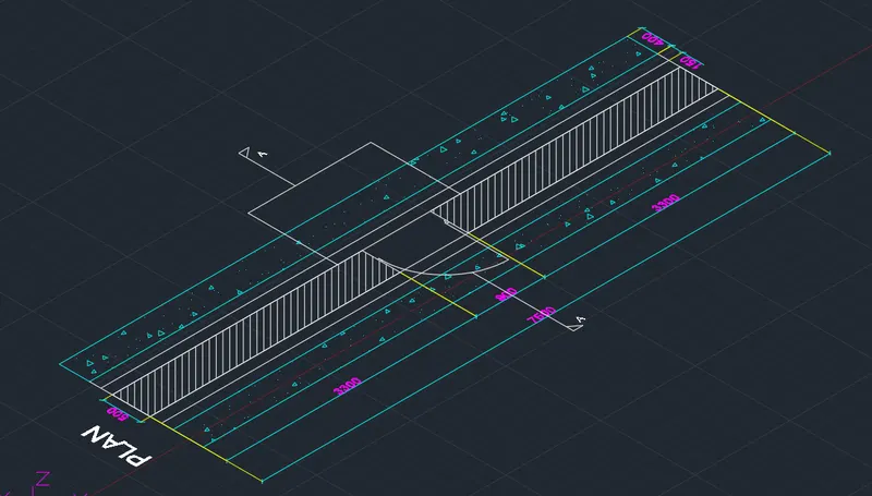
isometric view of 3d wall
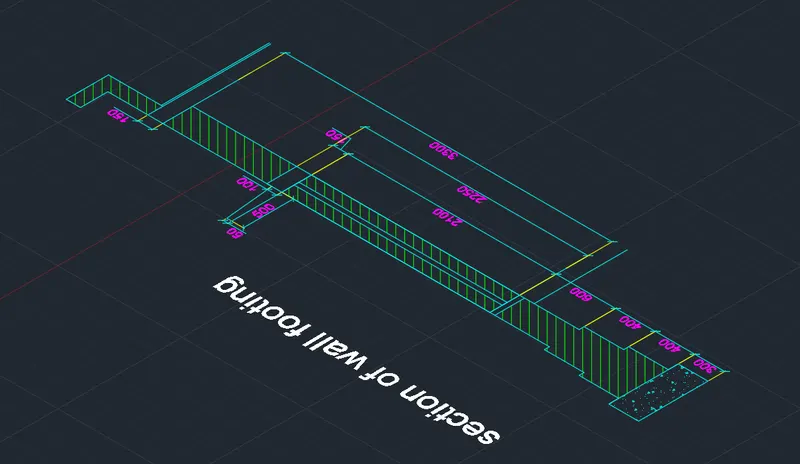
SECTION OF WALL FOOTING -
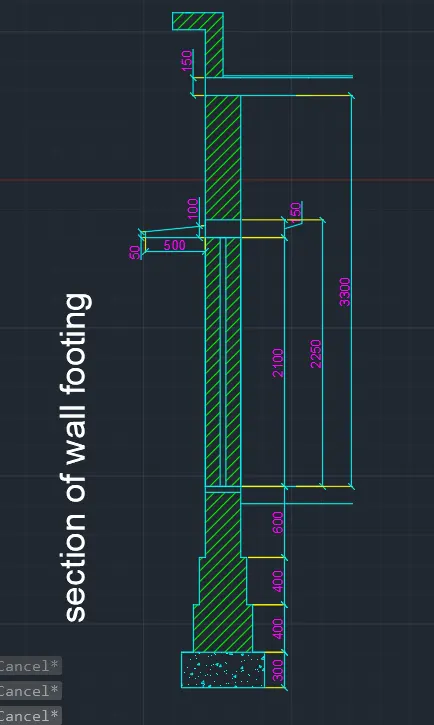
PROCEDURE -
FOOTTING - TO Create footing taking a rectangle and create @300,700mm size rectangle after that taking line tool taking 100mm offset from its top and create 400mm in vertical and take 500 mm offset in x direction again create 400 mm line in vertical direction and take 50mm offset and create 600mm line in verticle direction and closing its top line. from closing line taking 50mm offset and take a line tool to create above footing. and create 2100mm line in vertical directiion and close its top and provide 150mm offset again taking a line tool and create 1050 mm line in vertical direction. and mirror it all lines.
PARAPET - In center offset from its top provide 50mm line in -y direction and its bottom side taking a line tool and provide 500mm line from that point create 50mm line in y direction and join the line and having slope
dimension - to provide dimension use decimal unit and modifie changing text color is pink and create extension line is yellow provide dimension line is cyan color.
HATCHING - For hatching using ANSI31 and provide green color to hatching and set transperency according to block.
TEXT - using multiline text for the object.
ISOMETRIC VIEW OF THE OBJECT -
RESULT -