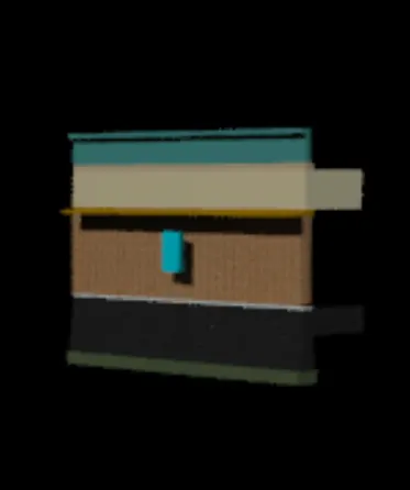
Creating 3D Isometric view of various structural elements in AutoCAD
1)AIM:
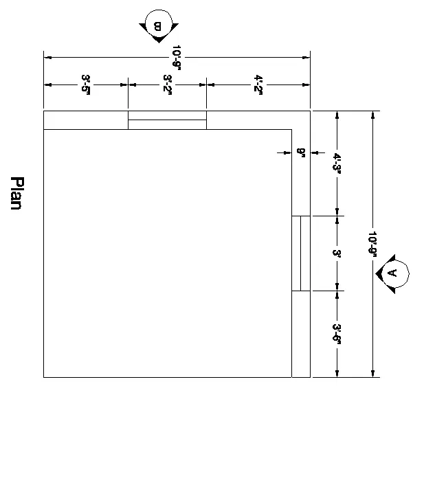
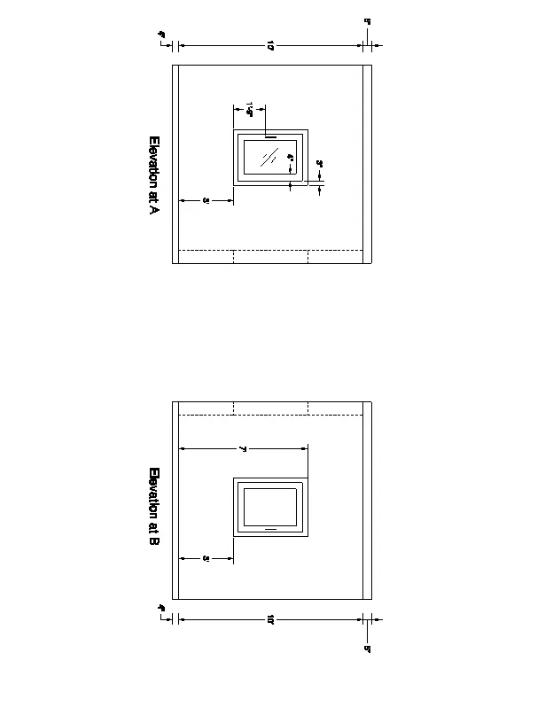
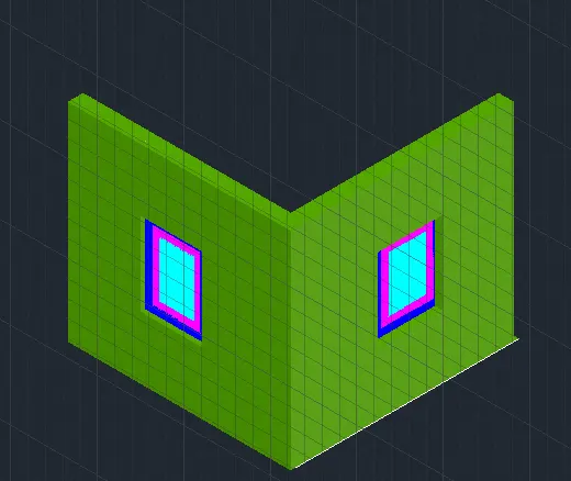
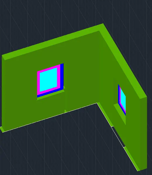
Create a 3D Isometric View of the building with plan and elevation given.
PROCEDURE:
Set the limits & units
Draw the given plan & elevation using line command as per given dimension
Mention the dimension using DIMSTY command
Create a words using MTEXT command
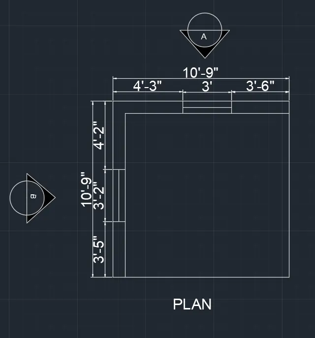
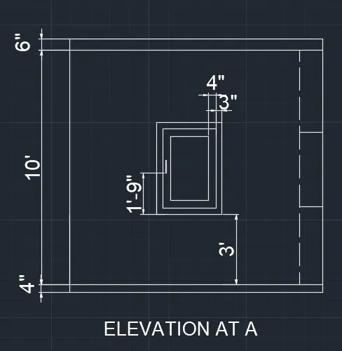
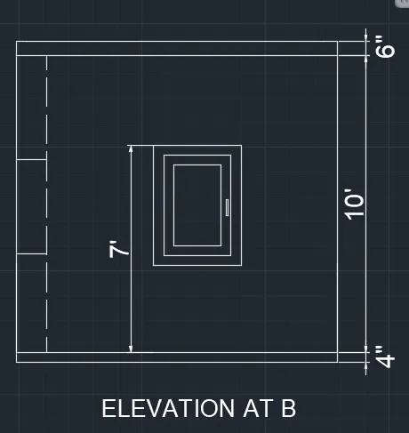
Go the settings change it to 3d modelling
Create layers using layer properties tool
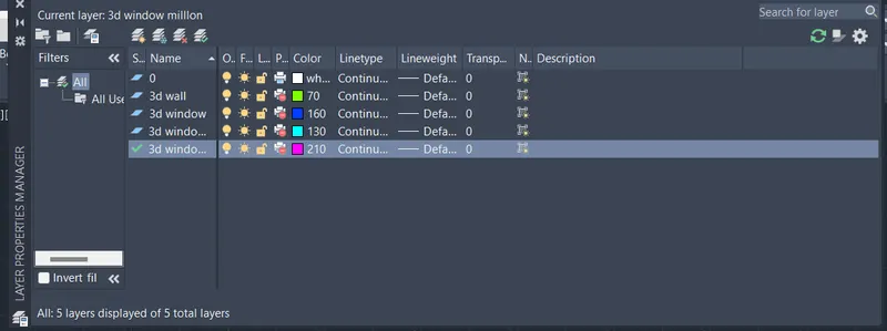
Create a region for the walls using BO command pick a point & create a region
Extrude the walls
Create a window to the given dimension & place it properly on the walls using move command
using union command convert the multiple object into single object
use 3Dorbit command to see the plan from different view
Use ucs command & face option to change the origin ,to create a line or rectangle where needed
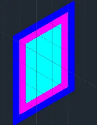
RESULT:
2)AIM:
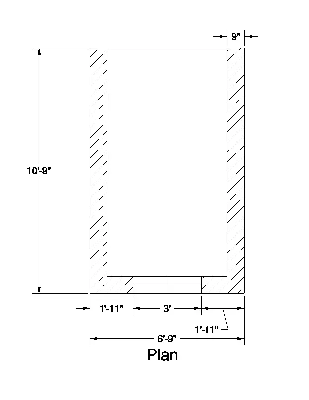
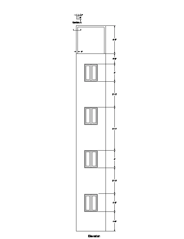
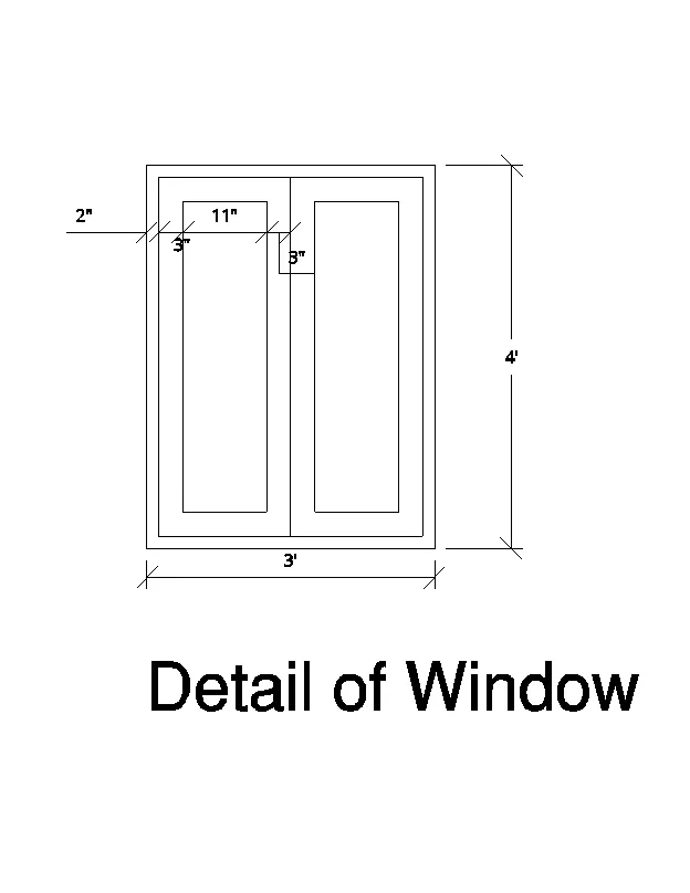
Create the 3D View of the Building Façade as given in the plan and elevation. Also, see the detail of the window.
PROCEDURE:
Commands used:
Line
Trim
MTEXT
DIMstyle
Hatch
3DROTATE
3DORBIT
Region
Union
Subtract
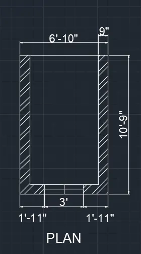
Create a given plan to the given dimension using line command
Mention the dimension using DIMSTYLE command
Go the settings & select 3D isometric
Create the region in the plan using region using command
Using extrude command extrude the plan to a height of 40'10"
Now create the rectangle in the window portion
Copy paste the 4 window of size 3'*4' vertically at a distance of 5'11"
Using Union command select the entire plan & given enter now the multiple object is coverted into single object
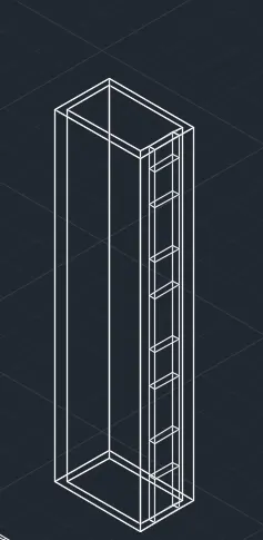
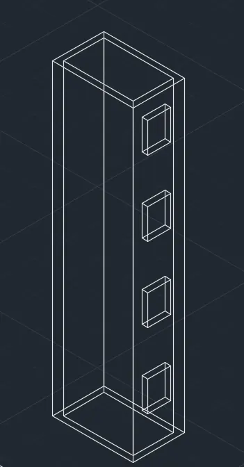
Subtract the window portion
Provide the layers for the building facade

Create the window to the given dimension using command BO,region & subtract
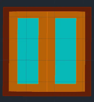
Now copy & paste the created window in the building facade at the subracted window portion region
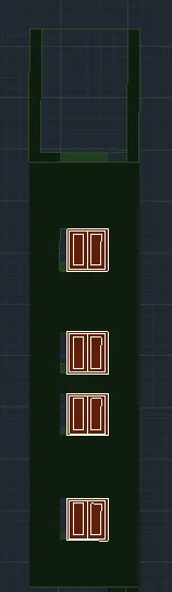
RESULT:
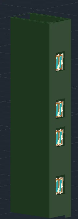
3)AIM:
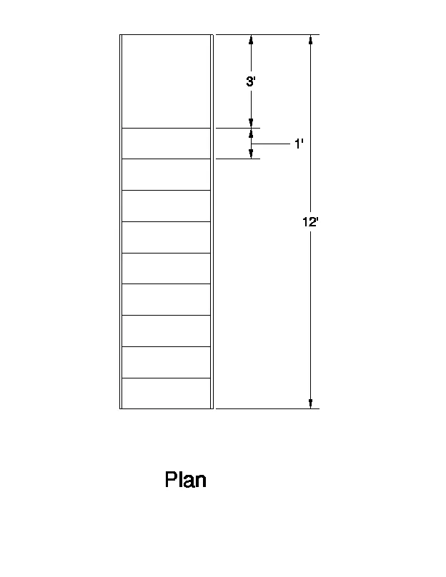
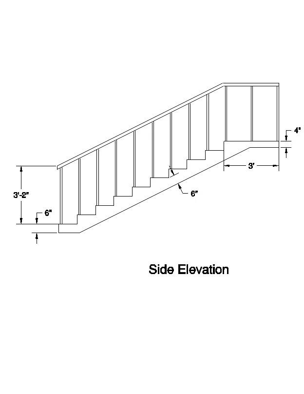
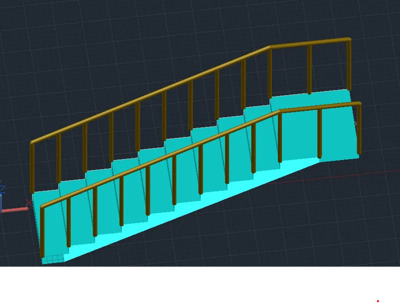
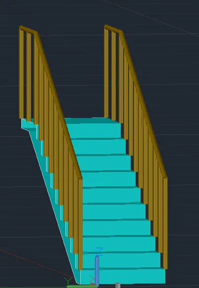
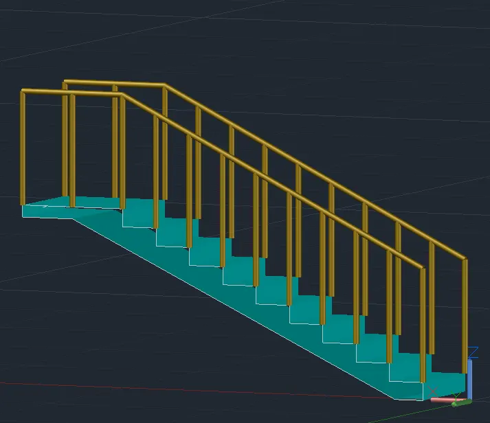
Create the ismoteric 3d view of a stair with railing as shown in the plan and elevation. Assume the size of the balustrades and the hand rails.
PROCEDURE:
Line
Trim
MTEXT
DIMstyle
Hatch
3DROTATE
3DORBIT
Region
Union
Subtract
Polysolid
sweep
Change the units to architectural precision 0'-0"
Using line command create a staircase of dimension riser 6" & tread 1'
Usinng 3drotate select the base point & x axis
Now extrude the staircase to a dimension 3'
Create railing using circle & sweep command
Use 3dorbit command to view the stircase from different position
RESULT:
4)AIM:
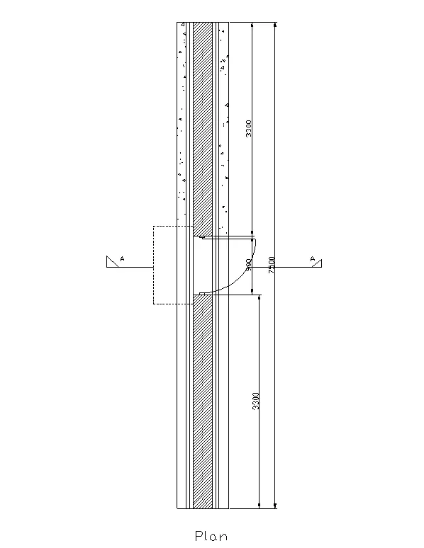
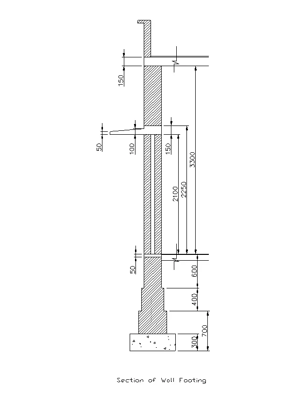
Create the 3D view of a Wall with spread footing . Create the Door opening only. Assume the size of the parpaet and the coping. See the plans and elevation for the details. Also, create a rendered view of the model with materials as of your choice.
PROCEDURE:
Create the wall footing to the given dimension using line command
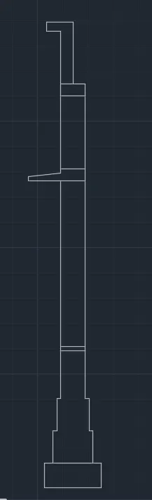
Now change the units to millimeter & extrude the wall to the given dimension
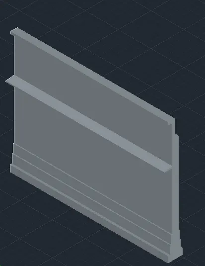
Provide different colours to the spread footing walls created
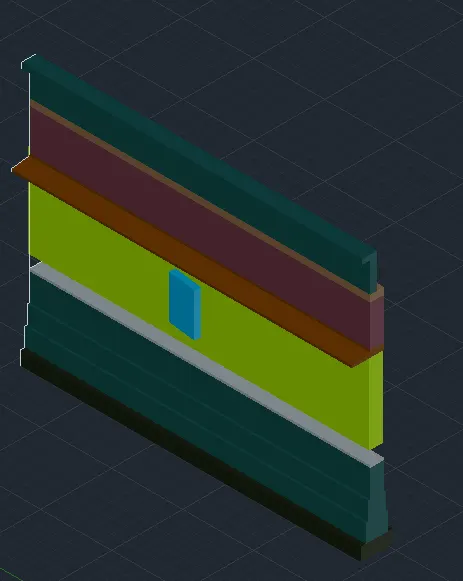
Provide different materials to the walls
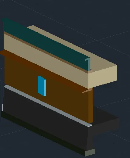
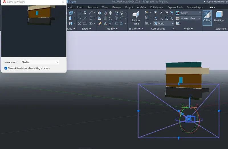
Select camera & place in the required position & give enter
RESULT: