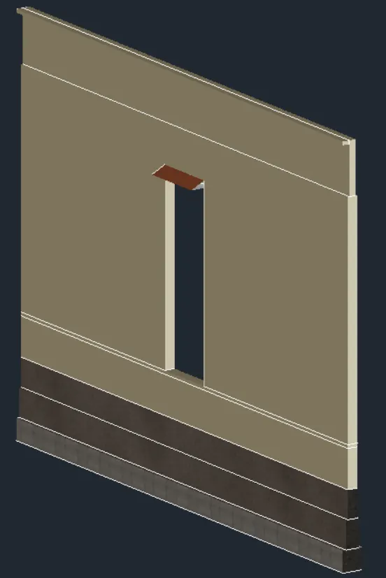
Creating 3D Isometric view of various structural elements in AutoCAD
QUE 1 ] Create a 3D isometric view of the building with plan AND elevation given
AIM - Create a 3D isometric view of the building with plan and elevation using AutoCAD
procedure-
- type units >engineering >0'-0"
- type Limax >100',100'
- type limits >0',0'
- Type zoom >a
- go to the top view use
- Use L command to draw the line of distance given and thickness
- type reg to the region the object
- type extrude to extrude the object
- type dim to give dimension
- go to right view and draft the rectangle using rec command
- using subcommand to subtract the windows
- type H to hatch the windows
- type rec and L to give the window detailing
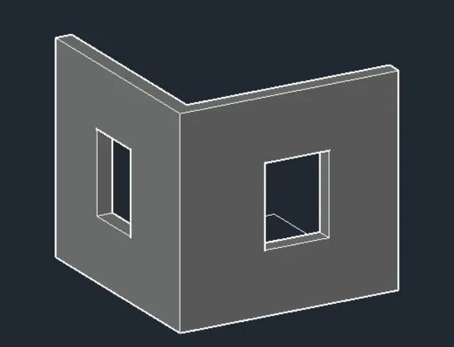
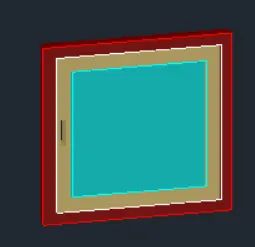
RESULT-
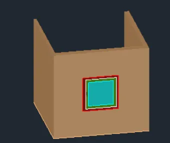
QUE 2 ] Create a 3D view of the building faces As given with plan and elevation
AIM ] Create a 3D view of the building faces As given with plan and elevation
procedure-
- type units >engineering >0'-0"
- type Limax >100',100'
- type limits >0',0'
- Type zoom >a
- go to the top view use
- Use L command and draft desired lines
- type dim to give dimension
- type mt to give text
- type reg to the region the object
- type extrude to extrude the object
- go to right view and draft the window using rec command
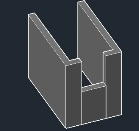
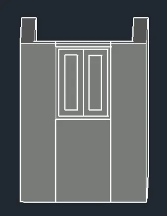
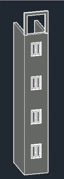
RESULT -
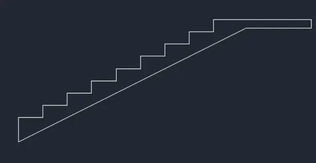
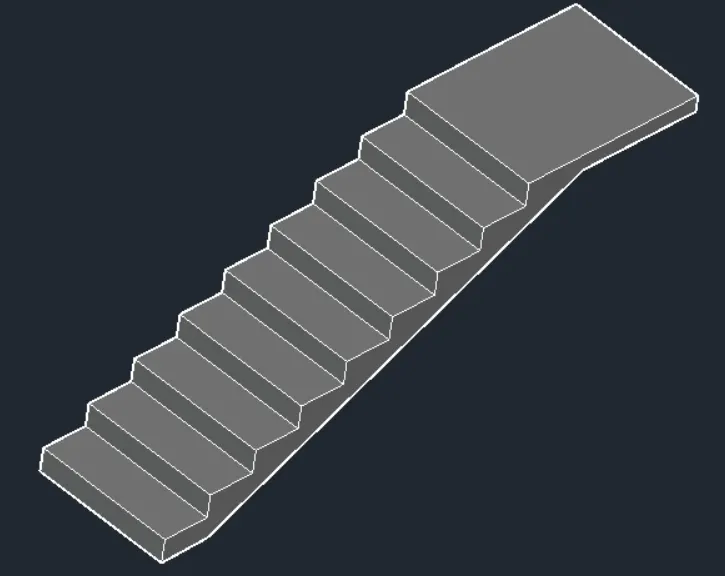
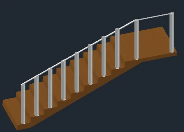
QUE 3 ] Create the 3D view of stair with railings as shown in the plan and elevation
AIM -Create the 3D view of stair with railings as shown in the plan and elevation using 3d AutoCAD
procedure-
- type units >engineering >0'-0"
- type Limax >100',100'
- type limits >0',0'
- Type zoom >a
- go to the top view use
- Use L command and draft desired lines
- in the top view plan is created
- go to the top view and create tread and riser with help of line command.
- type dim to give dimension
- type reg to the region the object
- type extrude to extrude the object
- create circle of dia.2
- extrude to distace of 3'2"
- type L and join railings
RESULT -
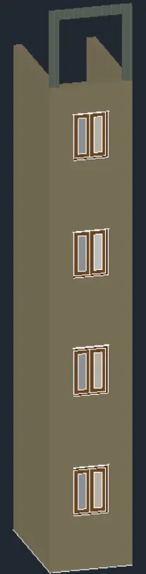
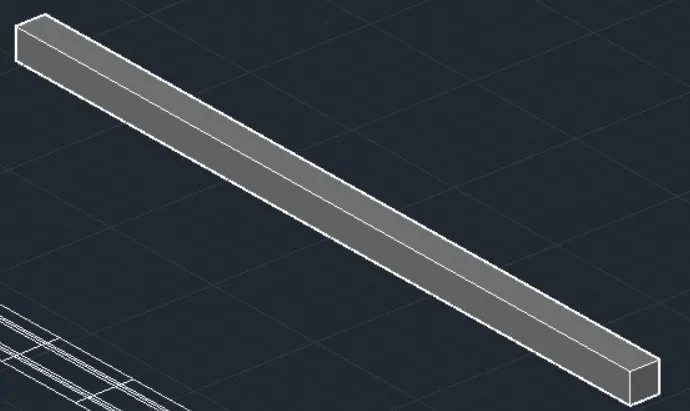
QUE 4 ] Create the 3D view of wall with spread footing created the door opening only assume the size of the parapet and the coping see the plants and elevation for details also create a render review of the model with materials as of your choice
AIM ] To create a 3D isometric view of wall spread footing and to also create a door opening using a autocad
procedure-
- type units >engineering >0'-0"
- type Limax >100',100'
- type limits >0',0'
- Type zoom >a
- go to the top view use
- Use L command and draft desired lines
- in the top view plan is created
- type H to hatch window
- type extrude to extrude the object
- type dim to give dimension
- in the ribbon bar>visualization>material browser>assign the material to each element
- in the ribbon bar>visualization>render to size
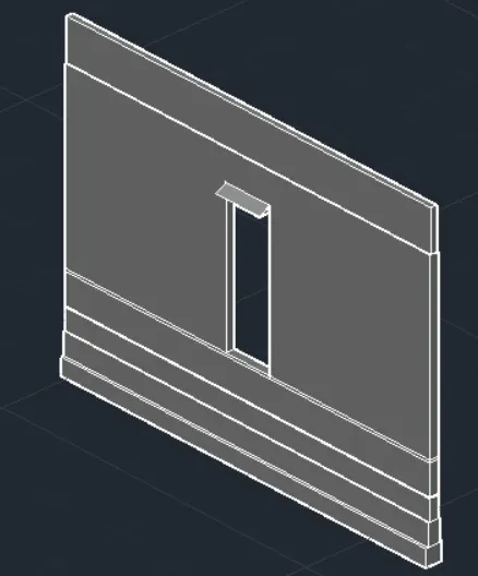
RESULT