Conjugate Heat Transfer Analysis on a graphics card.
OBJECTIVE
- Setup a case of Conjugate heat transfer in a graphics card (heat generation due to processor).
- Run the simulation with different air velocity and understand how it helps in heat transfer.
- Extract the max temperature and max heat transfer coefficient on the processor.
- Identify differnt hotspots for the case
THEORY
Conjugate Heat Transfer (CHT) refers to the coupling of conduction in solids with the conductive and radiative heat transfer in the surrounding fluids. It is used in processes that involve a variety of temperature within solids and fluids, due to thermal interaction between solids and fluids. This approach is used to undertake a thermal analysis and understand different ways of heat dissipation in different real-life scenarios. A few common examples of CHT are exhaust port, radiator, compressor, HVAC, heat exchangers, and computer system
During the computation, the processor consumes power and runs at its capacity and a large amount of heat is generated as a result. This heat needs to be actively removed from the system so as to ensure the proper functioning of our computer system. For these different cooling systems are installed like fans. This scenario is tried out in our study to understand how the heat generation takes place in the processor and how airflow affects the temperature built up in the system.
Following quantities are considered for the study
- Power output = 10 W
- Processor dimension = 8mm * 8mm * 1mm
- Heat Geneartion = 10/(64) = 0.15625 W/mm3 = 1.5625e+8 W/m3
PROCEDURE
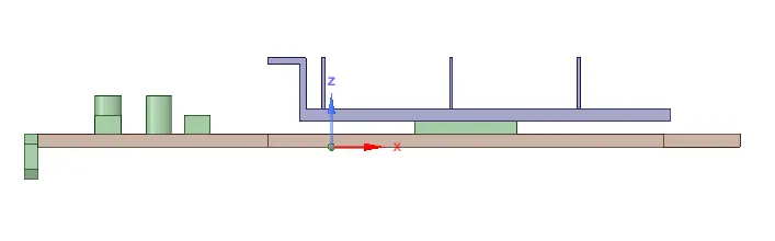
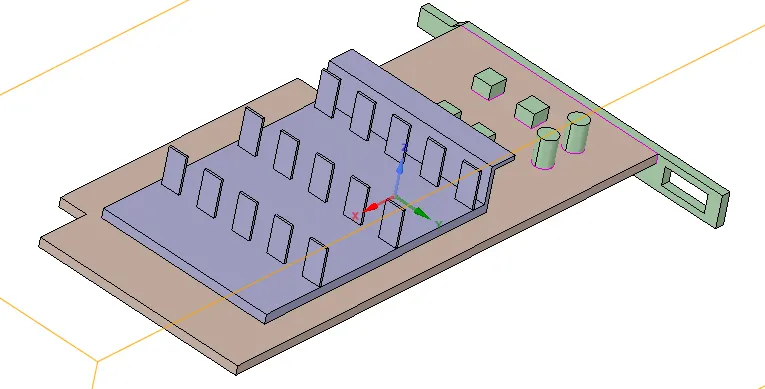
Geometry - Share the geometry to share the edges and faces among the geometry. This helps in creating conformal mesh.
Meshing
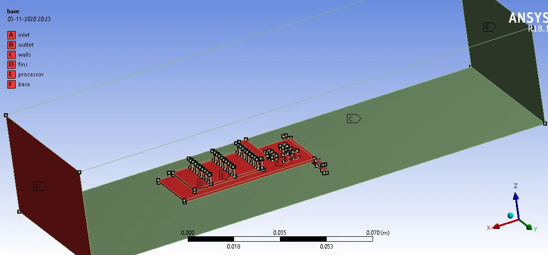
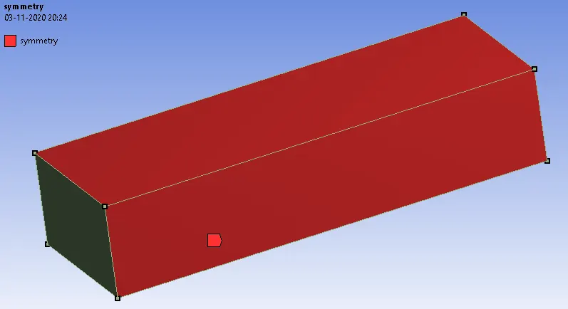
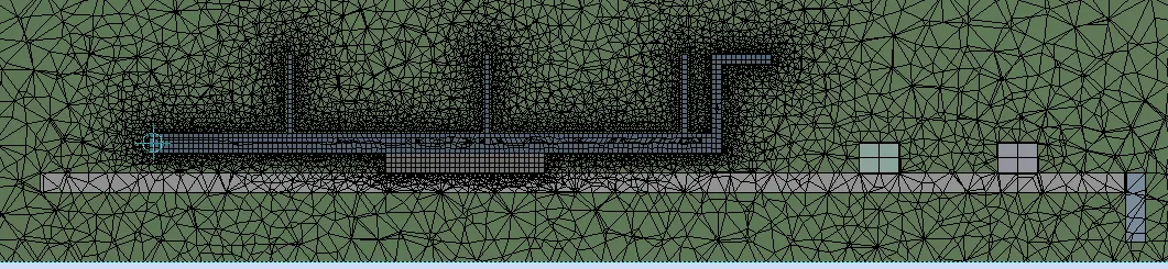
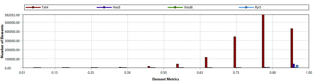
Case 1 - Baseline Mesh - Automesh - element size = 0.001 m
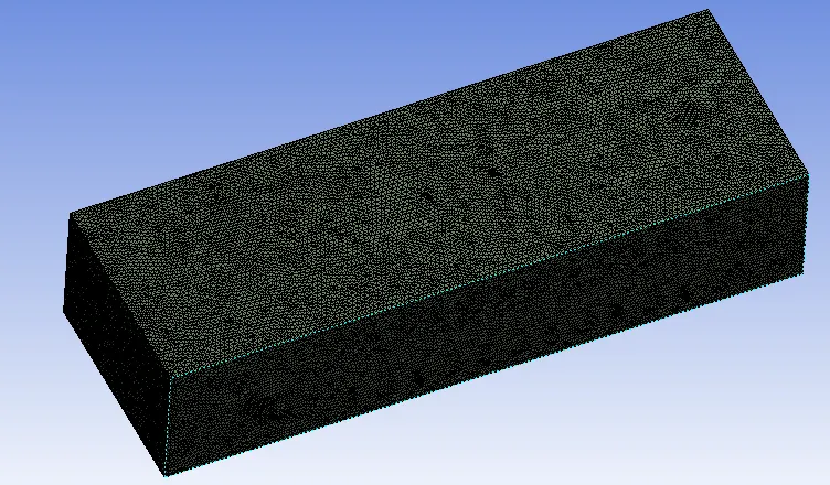
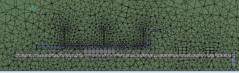
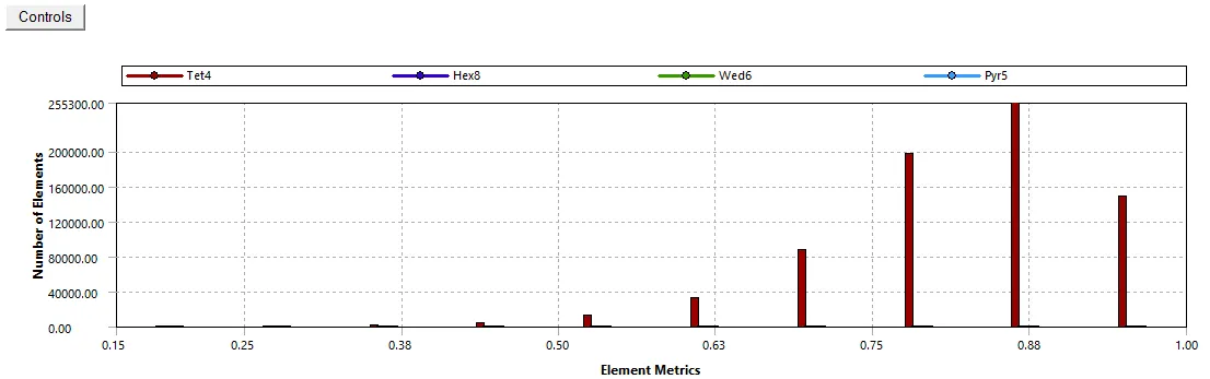
Case 2 - Refined mesh
Now we know that the key component in our study is processor, fin, and base. So we need to refine the mesh in these regions to better capture the heat exchange phenomenon
Processor, Fins, and Base - 0.00025 m
Enclosure - 0.001 m
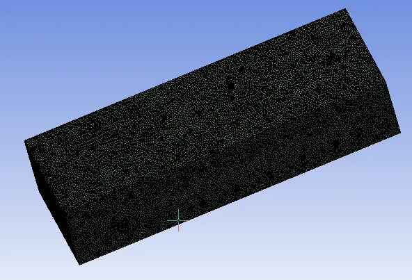
Setting up Physics
- Steady-state, Pressure based solver.
- Model - Energy equation - on, K-Epsilon standard wall treatment
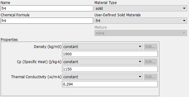
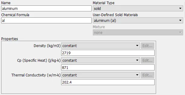
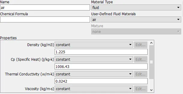
- Material - Enclosure = air, processor = silicon(created), fins = aluminium, base = FR4(created)
base:
Processor: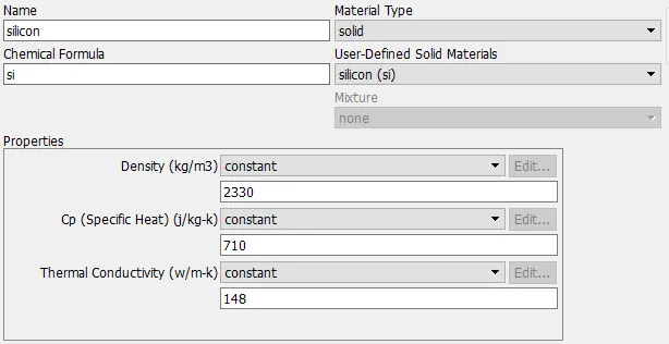
Fins:
Enclosure:
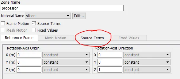
- Cell Zone condition - Assign proper material. Base, Fin and processor = Solid and enclosure = air. Enable source term in processor and provide input of heat generation as discussed above
- Boundary condition, 3 different velocities = 1m/s, 3m/s, 5m/s, temperature = 298.15 K or 25 oC
- Initialization - Hybrid (to setup up initial working condition inside the system)
- Run Calculation
RESULTS
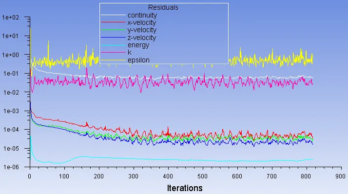
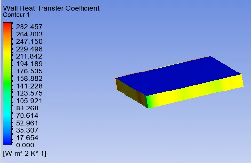
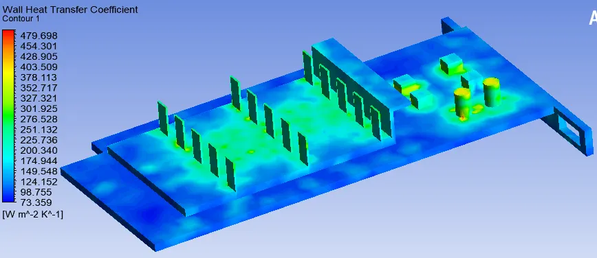
Case 1 - Baseline Mesh, airflow 3m/s, K-Epsilon standard wall treatment
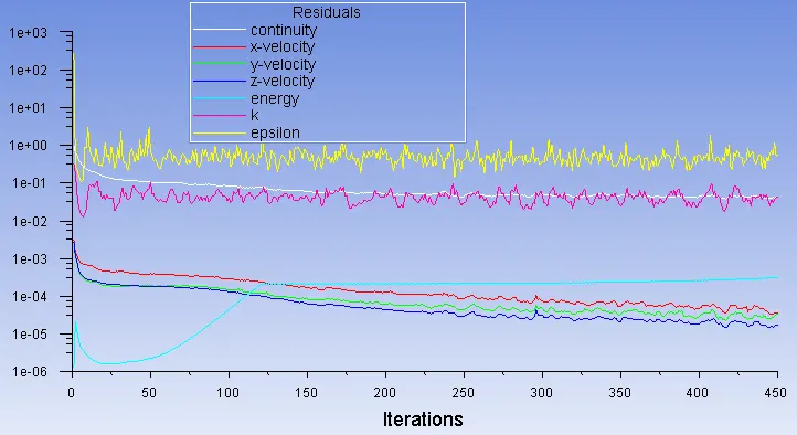
Residual
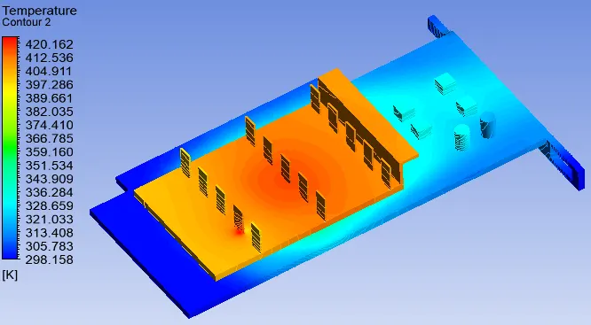
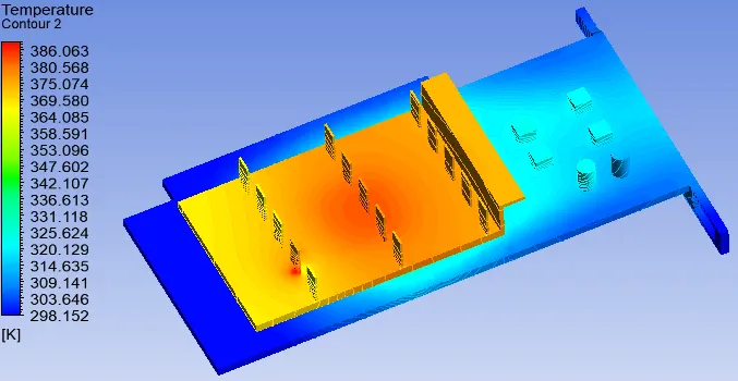
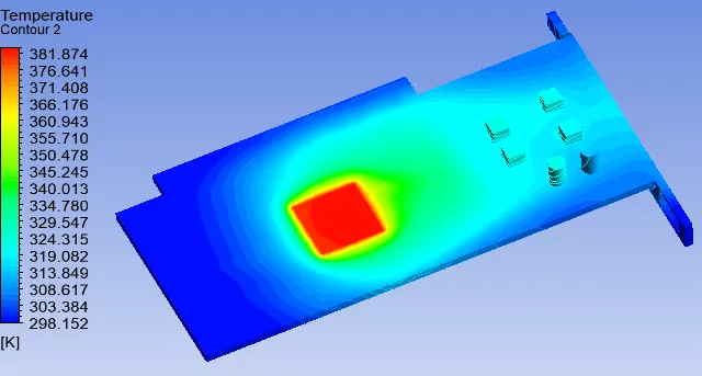
Temperature
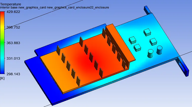
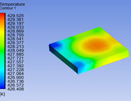
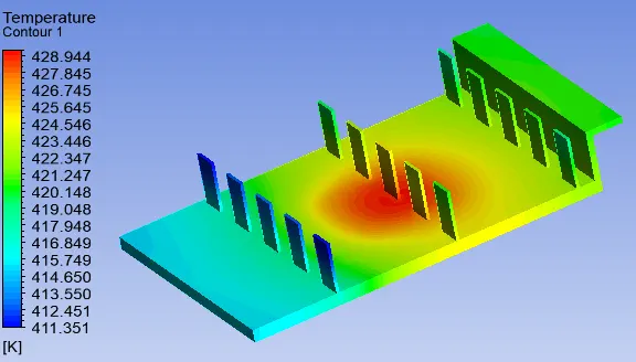
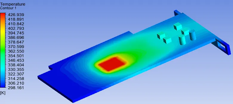
Wall Heat transfer coefficient
Processor
all components
Case 2 - Refined Mesh, K-Epsilon standard wall treatment
| 1 m/s | 3 m/s | 5 m/s | |
| Residuals | 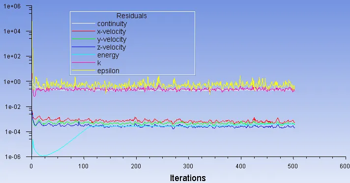 |
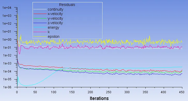 |
 |
| All parts | 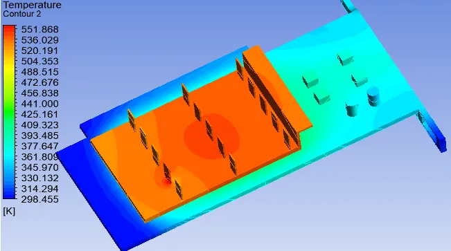 |
 |
 |
| Processor | 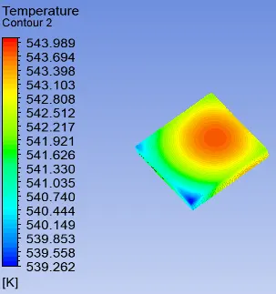 |
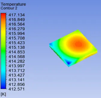 |
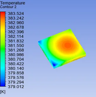 |
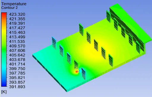
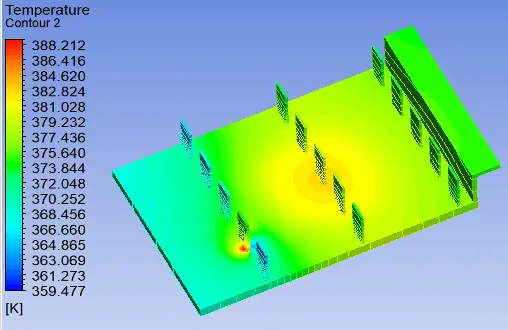
| Fins | 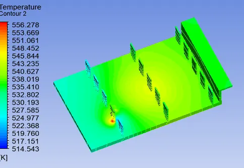 |
 |
 |
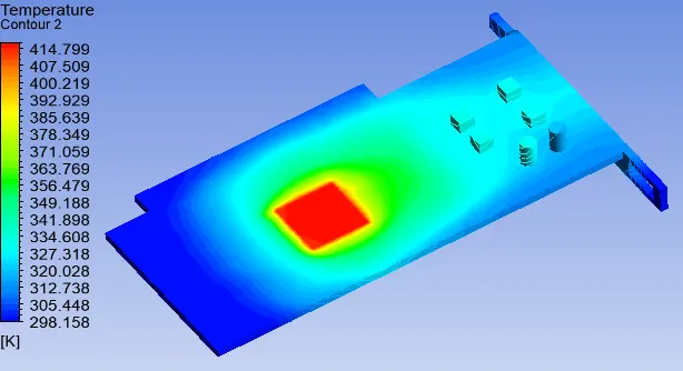
| Base | 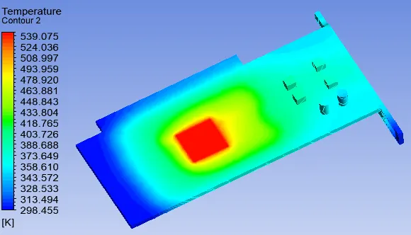 |
 |
 |
| Walls Heat transfer coefficient processor | 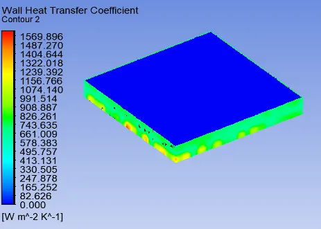 |
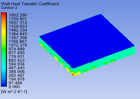 |
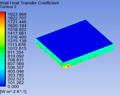 |
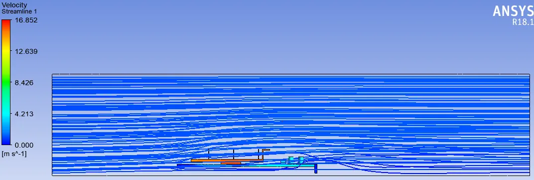
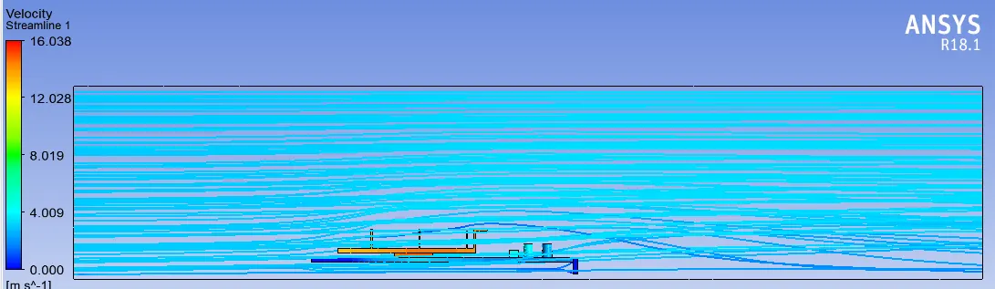
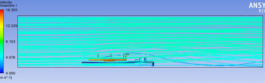
Streamline
1m/s
3m/s
5m/s
| Baseline - 3m/s | Refined -1m/s | Refined - 3m/s | Refined - 5m/s | |
| Nodes | 140753 | 327161 | 327161 | 327161 |
| Elements | 737519 | 1592646 | 1592646 | 1592646 |
| Max temperature (K) | 429.6 | 551.8 | 420.1 | 386.0 |
| Max temperature Processor (K) | 429.6 | 543.9 | 417.1 | 383.5 |
| Max temperature Fins (K) | 428.9 | 556.2 | 423.3 | 388.2 |
| Max temperature Base (K) | 426.9 | 539.0 | 414.8 | 381.8 |
| Wall Heat transfer coefficient processor (W/m2K) | 282.5 | 1569.9 | 1852.3 | 1923.9 |
DERIVATIVES
- A converged solution for the given sets of input was observed on the basis of repetitive plots in the Residual plot
- The processor acted as a source of heat input and thus one of the hotspots for such study
- With an increase in velocity, we saw a considerable drop in temperature and a substantial rise in heat transfer coefficient which shows that high-velocity air can be an effective mode of heat dissipation in graphics card
- From the temperature distribution, we can see hotspots in the fin and base near the surface that is in contact with the processor. Based on the thermal conductivity of the material this temperature is distributed accordingly amongst the component.
- We see a few high-temperature zones on fin away from processor depicting their high susceptibility to heat due to their geometry.
- Also, the difference in baseline and refined mesh is considerable and thus we can conclude that more refined mesh provides a better solution and can be used in optimizing the design for such applications.
REFERENCES
https://www.engineersedge.com/heat_transfer/thermal_properties_of_nonmetals_13967.htm
https://www.nuclear-power.net/silicon-specific-heat-latent-heat-vaporization-fusion/