Conjugate Heat Transfer Analysis on a graphics card.
Aim: To perform steady state conjugate heat transfer (CHT) analysis on Graphics card model.
Objective:
- Perform the simulation for different velocities i.e. 1 m/s, 3 m/s and 5 m/s.
- Predict numerically the maximum temperature and heat transfer coefficient attained by processor.
- Identify the potential hotspots in the graphics card model.
Introduction:
A graphics card is a part of hardware that is responsible for rendering image to monitor. It converts the data into signal understandable by monitor. The better quality Graphics card produces the smoother images for video editors and gamers.
Types:
Integrated: this is built in motherboard. And found in laptop.
Discrete: installed on the motherboard with the help of add-in card.
GPU stands for Graphics Processing Unit. It’s the brain of the graphics card and is what creates the visuals you see on the screen. The GPU works as a translator, it takes data coming from the CPU and transforms it into imagery.
There are two main manufacturers of discrete graphics cards, AMD and Nvidia- Some users have allegiances to a particular brand but each will do the same job. AMD also produce some integrated graphics option as well as the current market leader- Intel
Materials used:
|
Component |
Material |
Density (kg/m3) |
Sp. Heat (J/kgK) |
Thermal Cond. (W/mK) |
|
Motherboard |
Acrylonitrile butadiene Styrene (ABS) |
1050 |
1390 |
0.25 |
|
Processor |
Silicon |
2533 |
0.71 |
145 |
|
Fins |
Aluminium |
2719 |
871 |
202.4 |
Heat Generation in Processor:
Heat Generated: 10 W
Volume of processor: 64 mm3
Heat generation per unit volume: 10/ (64*10-9)
= 156250000 W/m3
Mesh:
A refined mesh is generated using proper mesh controls such as edge sizing, body sizing etc.
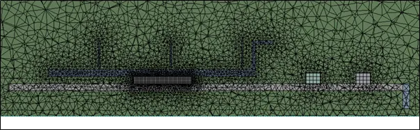
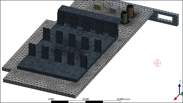
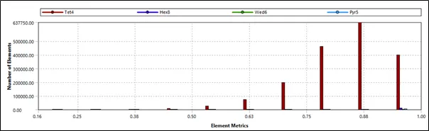
Number of mesh elements: 18,15,702
Element Quality:
Solution Setup:
Steady State , pressure based double presicion solver is used for solution. Cell zones are assigned with the proper material defoned in materials section. At inlet, velocity inlet and at outlet, outlet boundary conditions are specified.
Heat generation of 10 W is given as source term in processor cell zone.
Case 1: Velocity at inlet 5 m/s
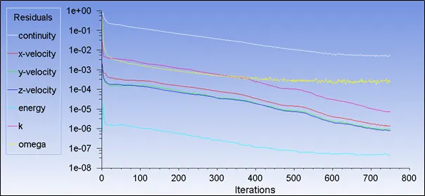
Residual:
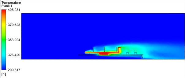
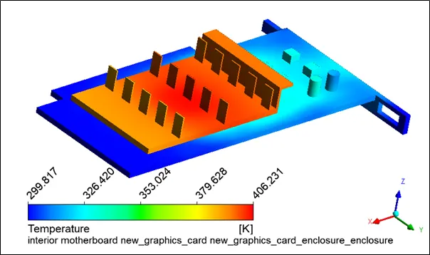
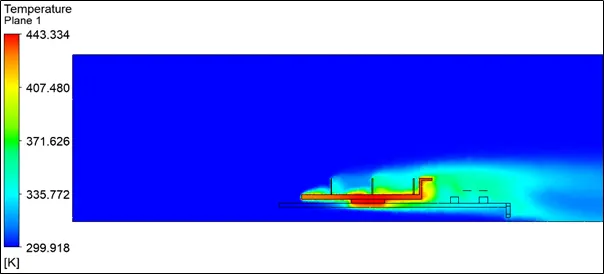
Temperature Contour on mid-plane:
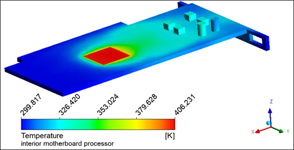
Temperature Hot-spot:
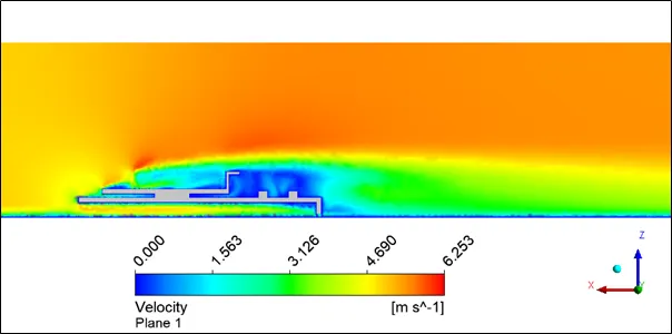
Velocity Contour on Mid-plane:
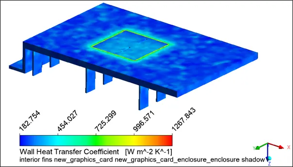
Wall HTC:

Case 2: Velocity at inlet 3 m/s
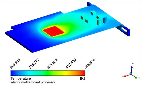
Temperature Contour on mid-plane:
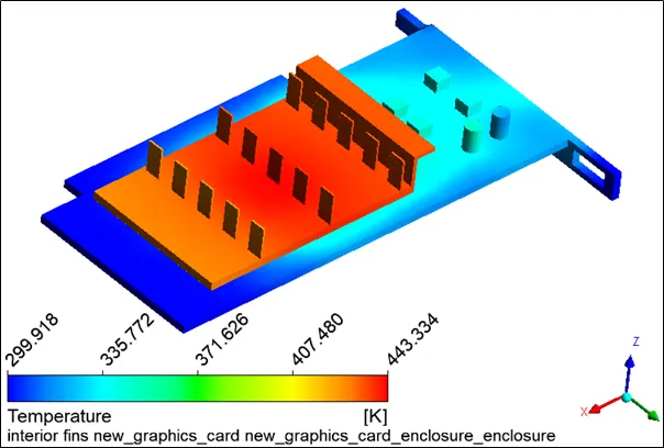
Temperature Hot-spot:
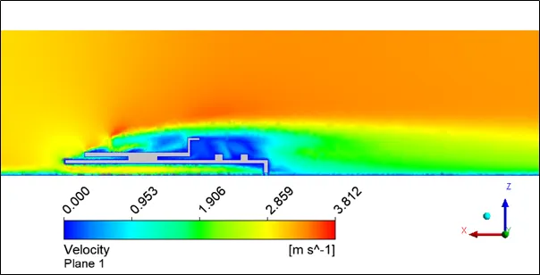
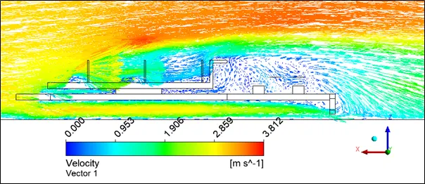
Velocity Contour on Mid-plane:
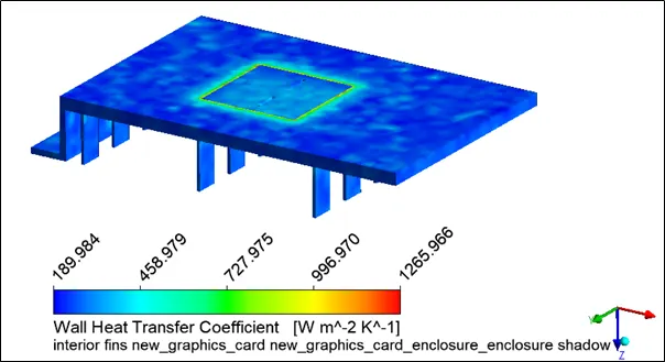
Wall HTC:

Case 2: Velocity at inlet 2 m/s
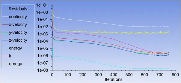
Residual:
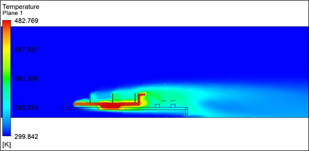
Temperature Contour on mid-plane:
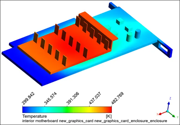
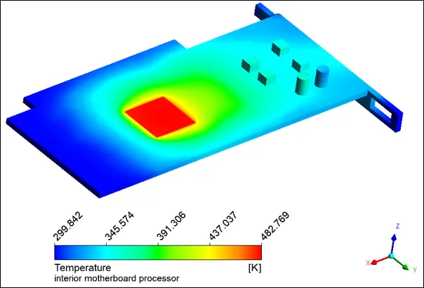
Temperature Hoy-spot:
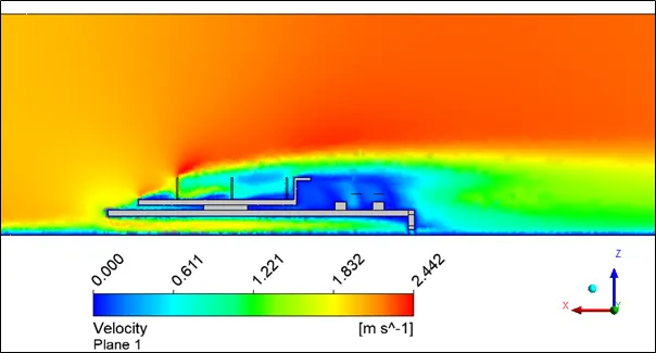
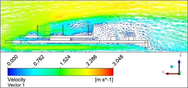
Velocity Contour on Mid-plane:
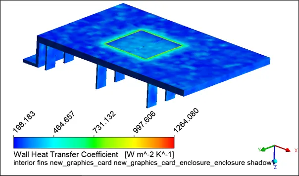
Wall HTC:

Conclusion:
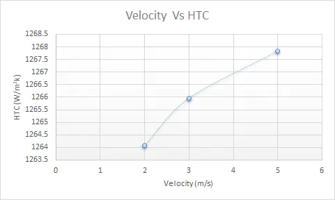
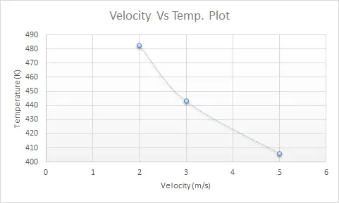
The results obtained from all three cases are shown in table below,
|
Velocity |
temperature |
HTC |
Area avgd. HTC |
|
2 |
482.769 |
1264.08 |
269.998 |
|
3 |
443.334 |
1265.96 |
270.964 |
|
5 |
406.231 |
1267.843 |
274.792 |
We can observe that as velocity at inlet is increased from 2 m/s to 5 m/s the maximum temperature is found to be reduced.
this is because, as we increase the velocity which will result in enhancement of HTC. and hence more heat is carried away from the fins by incoming air.
From velocity vector plots we can see that at higher velocity air flow can reach at the complex sections also that results in better HTC.
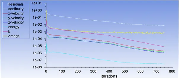
from the images attached in the report, it is observed that the simuation is converged properly.
And potential hotspots are found at the interface of processor and fins.