Conceptual design of a building with columns and shear walls
1.
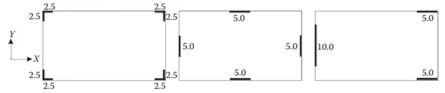
Answer:
A) Restraint of Floor Shrinkage:
Case(A)
- Shear walls are placed symmetrically at the four corners of the layout.
- The walls in the corner will tightly hold the floor in position thus RC wall system possess good control of shrinkage
Case(B)
- As the RC walls are provided in the center of the walls, this will provide better stability to the floor but the corners of the layout will prone to shrinkage.
Case(C)
- This system of wall is not considered as symmetric, the floor will have more shrinkage
B) Lateral stiffness:
Case(A)
- The shear walls are positioned only at the corners
- In case of earthquake,the forces acts in lateral movements,so it will possess less stiffness
Case(B)
- The structure will have better stability and lateral stiffness along both principle planes because the shear walls are located along the edges,and thus possess high stiffness
Case(C)
- This layout has two symmetrically placed walls in X direction and has only one shear wall in Y direction with different cross section from the other one.
- Thus the only shear wall which leads to the concentration of seismic force in that wall and reduces the lateral stiffness in that direction
C) Torsional one with respect to the vertical axis:
Case(A)
- It is clear that all the walls are placed symetrically in all the four corners of the layout, there is no chance of creating eccentricity as the centre of mass and centre of stiffness coincides. This is a case of torsionally stiff model.Hence less vulnerable to torsion.
Case(B)
- This arrangement is also a case of symmetrically placed wall systems at all the four edges of the floor.Therefor no chance of creating eccentricity as the centre of mass and centre of stiffness coincides. This is a case of torsionally stiff model.Hence less vulnerable to torsion.
Case(C)
- This layout has two symmetrically placed walls in X direction and has only one shear wall in Y direction with different cross section from the other one.
- This layout will experience torsion during the earthquake.
D) Vertical rebar at base:
Case(A)
- As the RC walls are placed at the corners,not in the principle plane,they will experience lesser lateral forces compared to other laytout,the amount of reinforcement will be lesser than other systems
Case(B)
- Here, a huge amount of the lateral forces are taken by the shear walls as they are placed along with the principal directions. Hence these walls required more vertical reinforcement than system A.
Case(C)
- Large amount of lateral force is taken in this layout because of the wall arrangement in this layout is designed in asymetrical way.
- Hence large quantity of reinforcement will be required for this layout
E) The Static Eccentricity:
Case(A)
- There is no eccentricity because the shear walls they are symmetrically located at the corners. The Centre of mass and stiffness coincides in this layout.
Case(B)
- In this arrangement, as the shear walls are symmetrically placed along the edges, the centre of mass and centre of stiffness coincides and there is no eccentricity.
Case(C)
- In this situatuion the shear walls are symmetrically placed along one of the principal direction, but in the y direction there is only one shear wall at the left edge with a larger cross section compared to other two shear walls. Hence, the centre of stiffness shifts to the left side and there occurs eccentricty in the model.
F) Foundation systems
Case(A)
- Isolated footing weill be suitable for this layout
Case(B)
- Mat or raft foundation will be suitable for this layout
Case(C)
- Combined footing can be provided along the Y direction and isolated footing in the X direction
G) Architectural constraints
Case(A)
- The walls are designed at the corner of the floor, it is Architecturally very effective as it will not obstruct any other elements
Case(B)
- All the four sides of the wall is partially obstructed, this RC wall arrengement will disturb architectural openings
Case(C)
- The RC wall on the left side completely obstructed where we can design no openings while the other sides are good to architectural point of view
2.
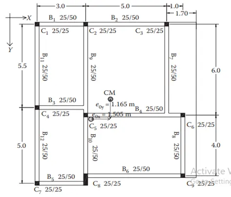
Aim:
- To observe the suitability for earthquake resistance of the moment resisting framing plan of a three-storey building
- To suggest an alternative plan
Observation:
- The columns and beams are not placed in grid patterns.
- Incomplete lateral load transfer in both X and Y direction.
- Beams are found to be stronger than columns, hence its strons beams and weak column which we dont prefer
- Load will not get transferred because of the beam and column position
Alternative plan:
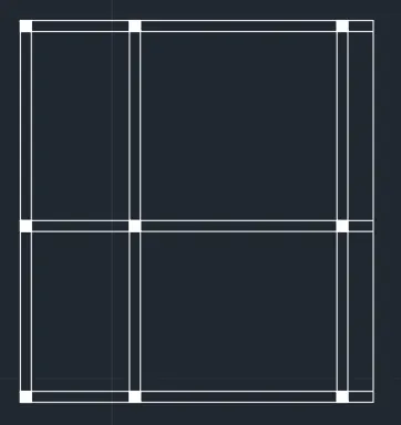
- The arrangement of the beam and columns can be done in the plan effectively that the load can be transferred effectively
- The columns and beams are now in a grid pattern which offers better resistance in lateral load
3.
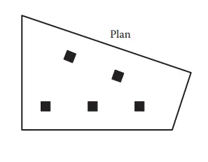
- Non uniform system layout.
- The beams and columns are not in grid position.
- The left side of the plan is larger than the right side of the plan so the center of mass lies somewhat to the left side of the plan and it leads to torsional irregularity.
- RC wall in L shaped can be provided at all the coreners of the layout for lateral stiffness.
- By providing RC walls torsional rigidity can also be maintained for the structure by distributing the mass accordingly.