Conceptual design of a building with columns and shear walls
CONCEPTUAL DESIGN OF A BUILDING WITH COLUMNS AND SHEAR WALLS
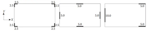
1. The building shown, 20 × 35 m in plan, has columns on a 5 × 5 m grid and shear walls (with dimensions shown in m, 250 mm in thickness) in three alternative arrangements, (a), (b), (c), all with the same total cross-sectional area of the shear walls. Compare the three alternatives, taking into account the restraint of floor shrinkage, the lateral stiffness and the torsional one with respect to the vertical axis, the vertical reinforcement required for the same total flexural capacity at the base, the static eccentricity, the system’s redundancy, foundation systems, architectural constraints etc.
Ans:
- Restraint of floor shrinkage:
Case 1:
Shear walls are positioned at corners. It offers strong resistance to floor shrinkage. The floor will be tightly held in place by these shear walls at the corners, and shrinkage will be controlled.
Case 2:
The shear walls are placed along the edges of the wall in all four sides. This wall will provide better stability to the floor near it but the corner portions of the floor are subjected to shrinkage, where there is no shear walls.
Case 3:
The shear walls are not placed symmetrical. Both the long edges and right short edge of the wall is prone to shrinkage as there is no shear wall at the right side and along the long edges the shear wall is placed only at the right most edge.
- Lateral stiffness:
Case 1:
The Shear walls are positioned only at corners, in the case of an earthquake the forces tends to act along the edges of the floor and will have low lateral stiffness and stability
Case 2:
The structure will have better stability and lateral stiffness along both principal planes because the shear walls are located along the edges, which is the same direction as the earthquake excitation.
Case 3:
In this case, along the x direction there are two shear walls which enhance the stiffness in that direction, whereas in the y direction, there is only one shear wall at the left which leads to the concentration of seismic force in that wall and causes instability and reduces the lateral stiffness in that direction.
- Torsional stiffness with respect to vertical axis:
Case 1:
The placement of shear walls is symmetric, hence there is no eccentricty between the center of mass and centre of stiffness, both coincides, so it is less prone to torsion and can be regarded as torsionally stiff model.
Case 2:
There is no eccentricity between the centre of mass and the centre of stiffness as the shear walls are positioned symmetrically and as a result, this configuration is less vulnerable to torsion.
Case 3:
The shear wall is placed asymmetrical in the y direction, so as a result, the centre of stiffness shifts to the left edge, resulting in an eccentricity between the centre of mass and the centre of stiffness, causing torsional instability in this configuration.
- The vertical reinforcement required at the base:
Case 1:
Since the shear reinforcements are positioned at the corners, they play a little role in the lateral force resistance to the remainder of the wall As a result, less reinforcement will be required for these walls.
Case 2:
The huge amount of the lateral forces are taken by these shear walls as they are placed along the principal directions itself. Hence, these walls should be provided with much more reinforcement to resist these forces.
Case 3:
In third case, as the shear walls are asymmetrically placed, large amount of lateral fores will be taken by the shear walls especially the wall at the left edge. Hence, these walls needs to be heavily reinforced.
- The static eccentricity:
Case 1:
As the shear walls are symmetrically placed at the corners, the centre of mass and centre of stiffness coincides and there is no eccentricity.
Case 2:
There is no eccentricity because the shear walls are symmetrically arranged around the edges, the centre of mass and stiffness coincide in this arrangement.
Case 3:
There will be eccentricity in the arrangement because there is only one shear wall along the left edge with a larger mass than the other two shear walls in the y direction. As a result, the centre of stiffness shifts to the left, resulting.
- The system’s redundancy:
Case 1:
The structure will have less redundancy, because this design contains shear walls at its corners which does not actively participate in resisting the lateral force, so the other parts of the structure must take care of a large portion of the lateral force.
Case 2:
The structure will have moderate to good redundancy, here as the forces are evenly distributed due to the symmetric placement of shear walls along the mid portion of each edge.
Case 3:
As this arrangement of shear walls is asymmetric and also there is concentration of load at the left edge, this arrangement is not redundant. It has poor redundancy in case 3 arrangment.
- Foundation systems:
Case 1:
As the shear walls are at the structure's corners, an isolated footing with a tie beam can be used as a foundation.
Case 2:
A raft foundation or a box foundation can be used.
Case 3:
In this arrangement two shear walls are provided at the along the x direction so for this a combined footing can be provided along y direction connecting these two shear walls. The other shear walls at the left edge can be provided with an isolated footing.
- Architectural constraints:
Case 1:
From an architectural standpoint, this shear wall configuration is pleasing. since it does not interfere with other elements such as doors, windows, etc.
Case 2:
While this design is stable, there is a potential that these shear walls will interfere with the wall openings, which is not ideal.
Case 3:
In this arrangement, the two walls at the right side along X direction is architecturally fine but the shear wall at left edge along y direction occupies almost half of the wall, which can cause hinderance to the open spaces.
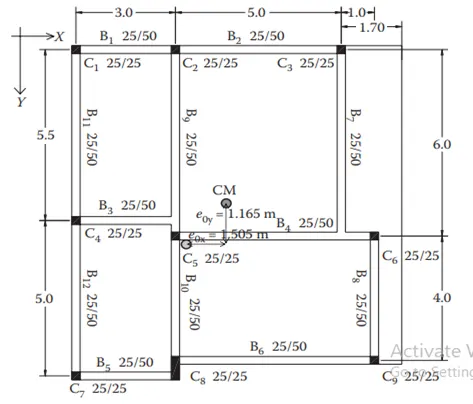
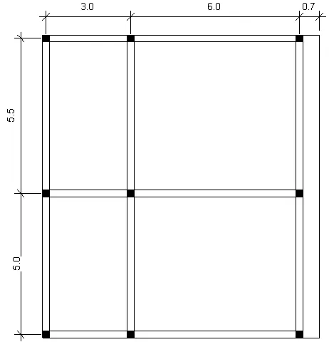
2. Discuss the suitability for earthquake resistance of the moment resisting framing plan of a three-storey building depicted here (cross-sectional dimensions in cm), the eccentricity of the centre of mass (as centroid of floor plan) to the centre of stiffness (from the moments of inertia of the columns) are shown. Suggest an alternative. Also, is there torsional flexibility? Are the two fundamental translational modes of vibration larger than the fundamental torsional mode of vibration. Discuss qualitatively.
Ans:
Strong beam Weak column possibility:
The size of column majorly as 25 cm X 25cm but all the beam have much deeper section inertia of beam vertually higher than the column if the column reinforcement is adequetly geater than that of beam we are ok and since we do not have the reinforcement detail this is doubtfull it is recmmended to have slight bigger sizes for column. Because the beams in this building are stronger than the columns, it can be considered a weak column strong beam design in nature.
Eccentricity:
This structural frame has a two-way eccentricity of the centre of mass in relation to the centre of stiffness, with the eccentricity of the x-direction being greater than the eccentricity of the y-direction.
Indirect Lateral load Transfer in X and Y direction:
The beam are connecting to another beam which is ineffective during lateral load transfer in such condition the primary beam is prone to shear failure.
Alternative plan:
Complex load transfer process is eliminated and regular structure has been created.
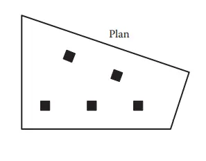
3. A multi-storey building with basement, with a quadrilateral (non symmetrical floor plan) plan as, has interior columns in an irregular (not in a grid) pattern in plan that serves architectural and functional considerations. Partition walls and interior beams supporting the slab have different layout in different stories. However, there is no constraint to the type, location and size of the lateral force resisting components and sub-systems on the perimeter. Proposals are to be made and justified for the choice of the lateral-load-resisting system and its foundation.
Ans:
Observations:
- The floor plan is neither uniform nor symmetric. So lateral load induced in the floor is not uniform.
- This layout is completely unsuited for earthquake prone locations.
- The partition wall is given through the base of the beam and should support the structure's lateral displacement.
- The internal columns are random.They are unable to transfer lateral load efficently.They are designed for only gravity load.
- The slab will be supported by the internal beams, with the lateral load resisting failure due to earthquakes.
- Partion wall provied an importance mass control in a building and beam play key role an shear transfer floor to beam. All this elemnts are not in oder. So heavy distrition and distribution of lateral lods will happen.
Suggestions:
- Heavy torsional force should be controlled by lateral load system. So corner shear walls are suggested for this plan.
- The floor area is greater than on left side than right side.so shear walls on left side is more heavier than right side shear walls.
- corner shear walls shall be supported over a box foundation and they are connected by links beams to transfer shear .
- Internal columns are supported by isolated footing and these isolated footings are connected with shear walls through tie beams.