Conceptual design of a building with columns and shear walls
Question 1:
The building shown, 20 × 35 m in plan, has columns on a 5 × 5 m grid and shear walls (with dimensions shown in m, 250 mm in thickness) in three alternative arrangements, (a), (b), (c), all with the same total cross-sectional area of the shear walls. Compare the three alternatives, taking into account the restraint of floor shrinkage, the lateral stiffness and the torsional one with respect to the vertical axis, the vertical reinforcement required for the same total flexural capacity at the base, the static eccentricity, the system’s redundancy, foundation systems, architectural constraints etc.
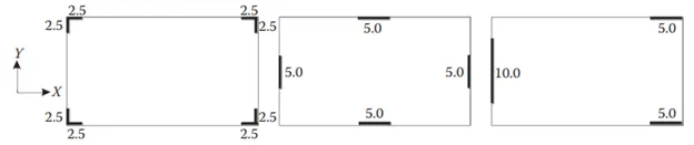
a) For the first figure:
1. Restraint of floor shrinkage: this RC walls system possess good control of shrinkage because all the corners of floor is restricted to experience shortening.
2. Lateral stiffness: this system will possess less stiffness because the RC walls is not in the principal plane but in the corners.Only the principal planes are subjected to lateral movements.
3. Torsion with vertical axis: centre of mass and center of stiffness will coincide so less prone to torsion.
4. Vertical rebar at at base: due to lesser lateral forces the verticall rebar will be lesser in comparision to other systems.
5. Static eccentricity: the system is eccentric with respect to mass-stiffness comparision.
6. System redundancy: as the RC wall is provided at the corners so it will be ineffective in dealing with the lateral forces, so the frame structures will need to take part in laterla load resisting system.
7. Foundation system: isolated footing with tie beam is suitable for this system.
8. Architectural contraints: form architectural point of view this arrangement is fine because only the corners are obstructed.
b) For the second figure:
1. Restraint of floor shrinkage: edges of floor is restricted to floor shortening so therefore the corners are more prone to shortening with frame system.
2. Lateral stiffness: this system will have better stiffness compared to other systems because the RC walls are in the direction of lateral force direction.
3. Torsion with vertical axis: centre of mass and center of stiffness will coincide so less prone to torsion.
4. Vertical rebar at at base: vertical rebar will be more than the previous system as the RC wall will take all the lateral loads in the principal direction.
5. Static eccentricity: the system is centric with respect to mass-stiffness comparision.
6. System redundancy: this system possess good redundancy because RC wall is effective in resisting lateral forces.
7. Foundation system: Box type foundation is suitable for this foundation.
8. Architectural contraints: this layout is not recoomended because it hinders with entrance.
c) for the third figure:
1. Restraint of floor shrinkage: this system will have more shrinkage effect because the floor is ot enclosed with RC wall at two sides.
2. Lateral stiffness: RC wall is stiffer in X direction for one side only and not stiffer in Y direction due to the presence of RC wall at only one side.
3. Torsion with vertical axis: centre of mass and center of stiffness will not coincide in both the principle directions.So this system will experience more torsion.
4. Vertical rebar at at base: This system has highest amount of vertical rebar because the RC wall is eccentic that these walls will experience extreme lateral and torsional moments.
5. Static eccentricity: the system is more eccentric with respect to mass-stiffness comparision.
6. System redundancy: this is the worst system in terms of redundancy because of concentration of loads at one side.
7. Foundation system: provide strip footing for Y direction RC wall and Isolated footing for X direction RC wall.
8. Architectural contraints: this layout is fine with the architectural point of view as only left side is obstructed.
Question 2:
Discuss the suitability for earthquake resistance of the moment resisting framing plan of a three-storey building depicted here (cross-sectional dimensions in cm), the eccentricity of the centre of mass (as centroid of floor plan) to the centre of stiffness (from the moments of inertia of the columns) are shown. Suggest an alternative. Also, is there torsional flexibility? Are the two fundamental translational modes of vibration larger than the fundamental torsional mode of vibration. Discuss qualitatively.
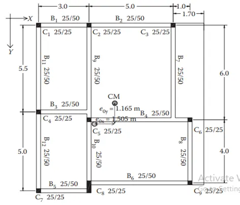
Aim: to observe the given structural framing in terms of seismic influence and to suggest better alternative for the same and in addition tell whether the given system needs to assessed for torsional flexibility.
Suitability for earthquake:
From the seismic point of view as it is a 3 storey building so a earthquake of moderate nature will affect this structure due to complexity in load transferring mechanism as we can see in the figure shown.The columns and beams are not in grid pattern they have offsetted from their path due to which load does not transfer effectively.
Alternative is that we can rearrange the columns so that load will be transfeered effectively.Also arrange the beam framing from column to column for the easy flow of lateral forces.
Main focus should be on making the grid of column and beam for effective resistance against lateral forces.Provide walls wherever possible for more resistance against lateral forces.
Torsional Flexibility:
Since the center of mass and center of stiffness of the building does not conincide so the building will definitely experience torsion with respect to vertical axis.The plan aspect ratio is less than 3 so we should assume that the given system is well proportioned.
The given vertical floor system is not effective in transferring lateral loads to vertical loads due to the offsets and beam to beam connections.The response of the building in fundamental mode of translational is the worst.
Yes, the two fundamental modes of translation may be still higher than the fundamental mode of torsion.
Question 3:
A multi-storey building with basement, with a quadrilateral (non symmetrical floor plan) plan as, has interior columns in an irregular (not in a grid) pattern in plan that serves architectural and functional considerations. Partition walls and interior beams supporting the slab have different layout in different stories. However, there is no constraint to the type, location and size of the lateral force resisting components and sub-systems on the perimeter. Proposals are to be made and justified for the choice of the lateral-load-resisting system and its foundation.
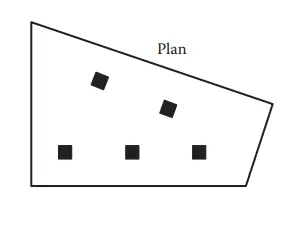
Comment on the plan:
As we can see from the plan that the floor area is not uniformly distributed so because of that the centre of mass will be somewhere on the left side of the floor plan.So the positioning of the lateral loading system be in such a way that their stiffness centre is near to the centre of mass so that torsional irregularity is avoided.
Lateral loading system:
As we can see in the figure the floor plan is an irregular quadrilateral.So during the occurance of seismic forces both the directions of earthquake will have infulence on each other because of the geometry.So the best option is to provide a L-shaped corner RC wall arrangement which will have bi-directional strength to resist seismic forces.
The foundations that can be taken for this arrangements are either isolated footings with tie beam connection or a box type foundation.