Conceptual design of a building with columns and shear walls
Question 1:
The building shown, 20 × 35 m in plan, has columns on a 5 × 5 m grid and shear walls (with dimensions shown in m, 250 mm in thickness) in three alternative arrangements, (a), (b), (c), all with the same total cross-sectional area of the shear walls. Compare the three alternatives, taking into account the restraint of floor shrinkage, the lateral stiffness and the torsional one with respect to the vertical axis, the vertical reinforcement required for the same total flexural capacity at the base, the static eccentricity, the system’s redundancy, foundation systems, architectural constraints etc.
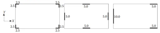
The obervations are done based on the given figure and based on the restraint of floor shrinkage, the lateral stiffness and the torsional one with respect to the vertical axis, the vertical reinforcement required for the same total flexural capacity at the base, the static eccentricity, the system’s redundancy, foundation systems, architectural constraints and the respected conclusions are made.
Observations:
A)
- As per the image given the corners of the building are provided with shear walls in L-shape so, fully restraint at all corners.
- Lateral stiffness will be comparatively less in both x and y axes as the walls at the corners will not handle the load
- But resistance to torsion with respect to vertical axis will be high as the shear wall are in the corners
- The flexural moment will be nominal and twisting moment will be high
- It is structurally symmetric and has uniform lateral supports at both the axes.
B)
- As per the image given the walls are provided at the four edges of the building with rectangular shape and the restraints are also at the edges.
- Lateral stiffness will be high and uniform in both x and y axes as the walls are uniformly provided in edges.
- Torsion resistance with respect ro vertical axis will be considerably good due to the walls at the edges.
- There will be a nominal flexural and twisting moment in the structure.
- It is structurally symmetric and has uniform lateral supports at both the axes.
C)
- As per the image given the walls are provided in a unsymmetrical manner and restraints are non-uniform as the walls are non-uniform
- The lateral stiffness will also be non-uniform in both the directions.
- Irregular placement of walls also leads to less resistance to torsional resistance and also subjected to heavy flexural and twisting moments
- It is also observed that the structure is subjected to concentrated lateral load in both the axes.
The conclusions with respect to given parameters from the observations are
Restraint of floor shrinkage: A and B exhibits hight restraint to shrinkage and are prone to cracks at floor surface compared to C as C has non-uniform walls and restraints.
Lateral stiffness: B will provide higher lateral stiffness than A and C when subjected to seismic force at x and y direction as walls are uniformly provided at edges.
Torsion with respect to vertical axis: A has more resistance to torsionsal resistance than B and C as walls are at corners.
Vertical reinforcement: C will require more vertical reinforcement than A and B as C expereinces heavy moments.
Static eccentricity: On comparison C will have static eccentricity as it is unsymmetric.
System's redundancy: A and B will be have more redundancy as they have uniform load supports.
Foundation systems: The design and of foundations systems for A and C will be critical compared to B as they have L-shapes walls and concentrated loads.The geometry of foundation will be easy for B and C compared to A.
A should be designed with peripheral box type foundation.
B and C should be designed with isolated/strip type of foundation.
Architectural constrains: The main architectural constrain is the accesibility of floors without any obstruction of strucural elements and in that case A can be preferred since it has walls at the corners only. B can be approved after discussions and C is not acceptable as it blocks the entire left corner of the structure.
Question 2:
Discuss the suitability for earthquake resistance of the moment resisting framing plan of a three-storey building depicted here (cross-sectional dimensions in cm), the eccentricity of the centre of mass (as centroid of floor plan) to the centre of stiffness (from the moments of inertia of the columns) are shown. Suggest an alternative. Also, is there torsional flexibility? Are the two fundamental translational modes of vibration larger than the fundamental torsional mode of vibration. Discuss qualitatively.
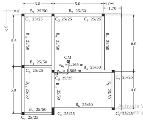
From the given image it can be clearly seen that the Beam B3 and B7 resting on beams B9 and B4 respectively rather on columns which leads to ineffective lateral load transfer and it can also be observed that the beams B5 and B6 eccentrically over the column C8 which the code prohibits. In case of beams resting on other beams shear failure occurs in primary beams.
Torsional moments or torsional flexibility will be higher if the eccentricity i.e, the distance between centre of mass and centre of stiffness is higher. In the given image it can be clearly observed eccentricity occurs in both x and y directions hence, torsional flexibility will be higher in both x and y directions and it can be higher than the two fundamental translational modes of vibration as it also have a cantilever slab at one side of the structure.
Another interpretation found in the given strucure is that the sizes of beam depth is significantly higher than the column sizes which might lead to a possibility of strong beam weak column design and ultimately which leads to soft storey mechanism and cause of column failure at first place when subjected to seismic force.
Alternative suggestion: The plan can be changed in such a way that the columns C4,C5,C6 and C7,C8,C9 can be aligned in the straight line. Smilarly columns C3,C6,C9 can also be aligned in straight line and thereby reducing the length of cantilever slab. By aligning of C7,C8,C9 columns in straight line a small cantilever beam and slab can be introduced spanning from C7 to C8 therby reducing the ineffective lateral load transfer in beams.
Question 3:
A multi-storey building with basement, with a quadrilateral (non symmetrical floor plan) plan as, has interior columns in an irregular (not in a grid) pattern in plan that serves architectural and functional considerations. Partition walls and interior beams supporting the slab have different layout in different stories. However, there is no constraint to the type, location and size of the lateral force resisting components and sub-systems on the perimeter. Proposals are to be made and justified for the choice of the lateral-load-resisting system and its foundation.
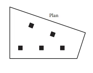
The observations from the given image and are that the floor plan is not symmetrical so any lateral load induced on the building will not have a symmetrical transfer of loads. The interior columns provided are irregular in pattern and are not subjected to any change in position hence, lateral load transfer will be in-efficient and it can only be designed for the gravity loads it expereinces. The other major data given is that the partition wall and beam plan differs from one storey to another which affects the shear transfer and leads to heavy tranfer of lateral loads.
Suggestions or proposals:
Due to the architectural constrains the given column position cannot be changed and beam plan also differs. Hence, corners of the building should be provided with shear walls connected with beams for load transfer. The mass of the shear wall will be higher on left side of the building as the plan has more floor area on the left side.Box type foundation is suggested for shear walls in the corner and isolated footings for the internal and both should be connected with tie beams.These are the possible suggestions for the design of this irregular pattern of building.