Challenge on Combustion
Combustion Simulation on Ansys Fluent
Aim-To simulate combustion simulation on a combustor model
Introduction
Combustion is a high-temperature exothermic redox chemical reaction between a fuel (the reductant) and an oxidant, usually atmospheric oxygen, that produces oxidized, often gaseous products, in a mixture termed as smoke. Combustion does not always result in fire, but when it does, a flame is a characteristic indicator of the reaction. While the activation energy must be overcome to initiate combustion, the heat from a flame may provide enough energy to make the reaction self-sustaining. Combustion is often a complicated sequence of elementary radical reaction.A combustor is a component where combustion takes place. It is also known as a burner, combustion chamber or flame holder. A combustor must contain and maintain stable combustion despite very high air flow rates. To do so combustors are carefully designed to first mix and ignite the air and fuel, and then mix in more air to complete the combustion process.
Types of combustion simulation on ansys fluent
1.On the basis of mixing
a) Non premixed combustion
In this type of combustion the fuel is injected just before the combustion. In this this type of combustion the fuel and air are not properly mixed
b) Premixed combustion
In the type of combustion the fuel is mixed to the air way before the combustion starts. Mixing air and fuel using a carburetor in an IC engine is an example of this type of mixing.
d) Partially mixed
This type of mixing is a combination of both non premixed and premixed combustion
2.) On the basis of Phase
a) Fluid phase
In this combustion the fuel is the fluid phase
b) wall
In this the combustin takes place on a wall or a surface
c) Particle
In this the combustion takes place on the surface of the particle
d) Porous Region
The combustion takes place inside the pores of a solid
PROCEDURE
1.) Setting up the geometry
For this simulation a model of combustor is uploaded on spaceclaim. We can simulate the combustion on the 3D model but its will take alot of time to do so also it will exceed the maximum number of cells allowed of the academic licence of Ansys Fluent. Therefore we will simulate an axisymmetric simulation. But for 2D axisymmetric simulation we have to keep two thing in mind. First that the geometry should be in XY Plane and second the axis of symmetry should be on X-axis.Keeping this is mind the geometry was made.
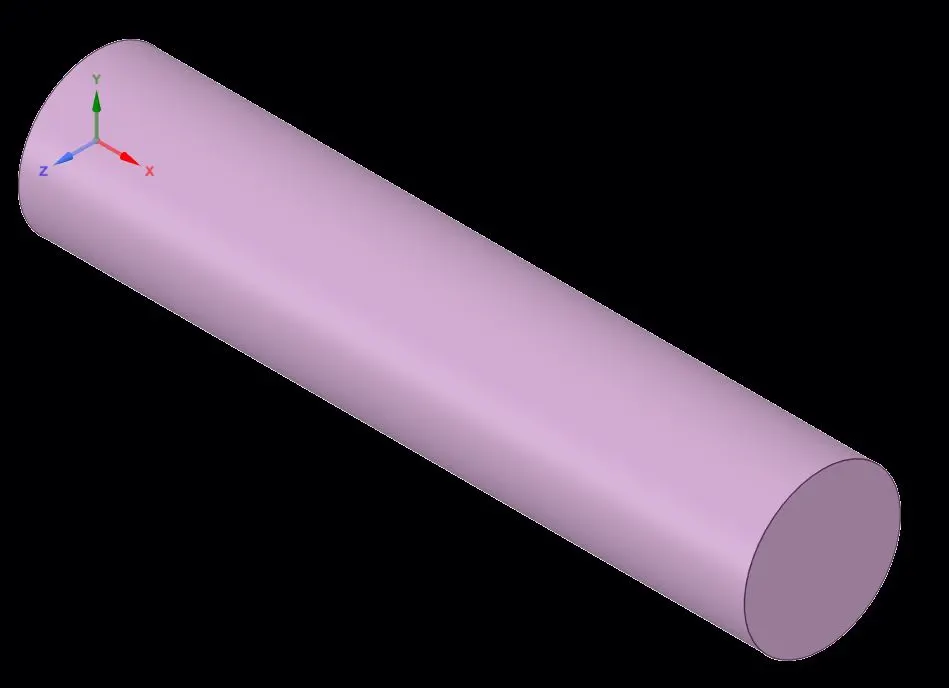
Figure 1- 3D Image of combustor

Figure 2- 2D geomety
2. Meshing
Then the geomety was meshed. The mesh generated is triangular mesh with element size of is 2mm.The option of Capture proximity was also turned on.Also the inlet for air and fuel,Outlet , walls and symmerty axis were named.


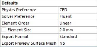
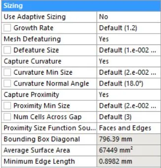
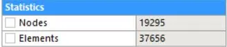
figure 3 -Image and Details of Mesh
3. Setup
Then fluet was opened. A steady state simulation was pressure based solver is used for the simulation.Then the setting of 2D was set to axisymmetric. The turbulance model used is Standard k-epsilon model with standard wall function.The energy equation was also turned on. In the spicies model, The spicies transport model is used and for Chemistry Interaction Eddy dissipation model is used. For mixture Material Methane-air is used.In boundry condition the inlet velocity for air is set at 0.5m/s and for fuel is set as 80m/s .
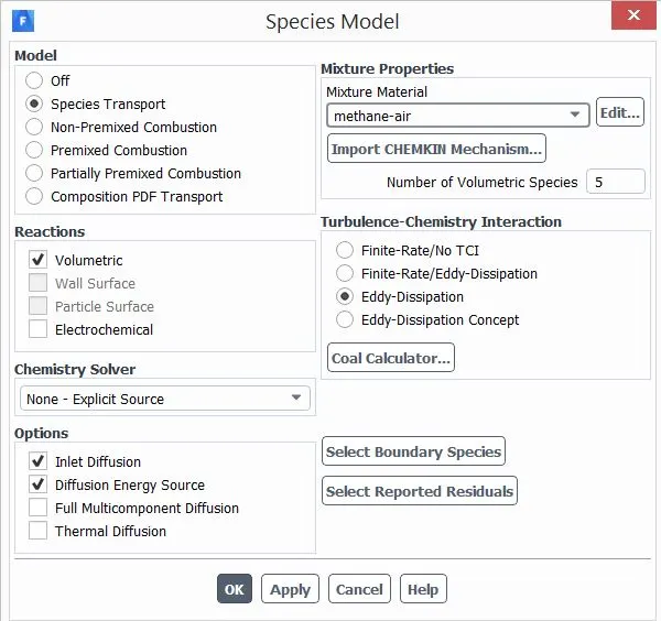
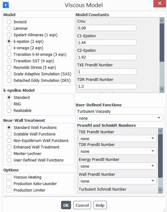
Figure 4- Setup Details
4.Simulation
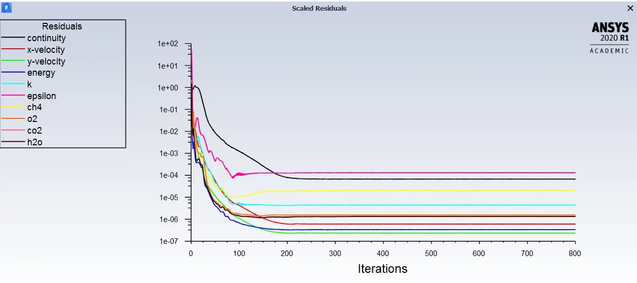
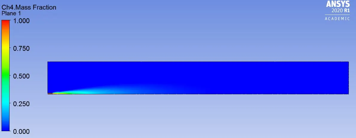
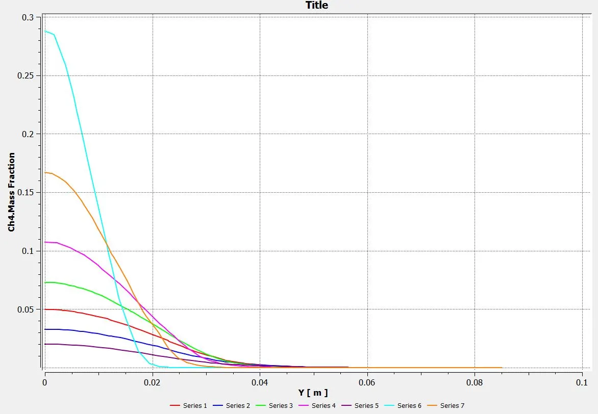
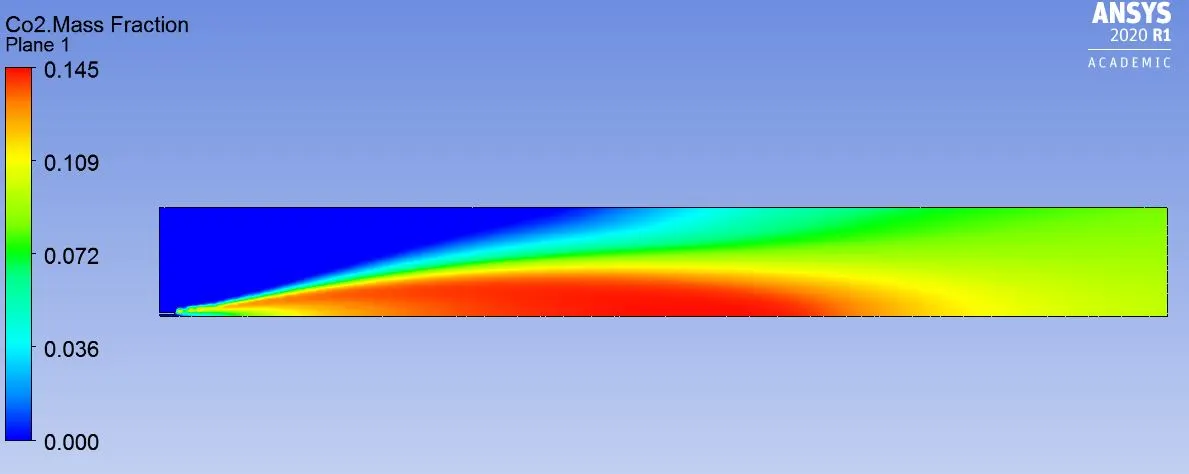
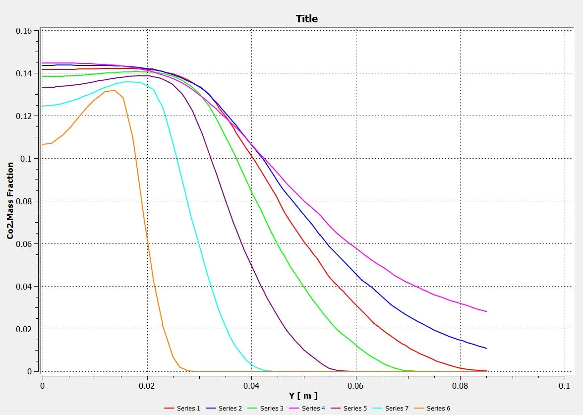
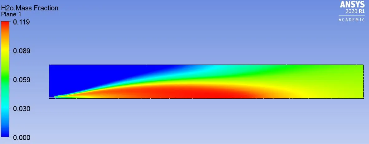
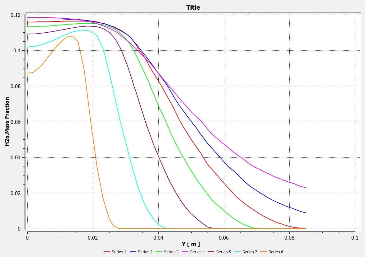
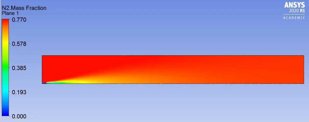
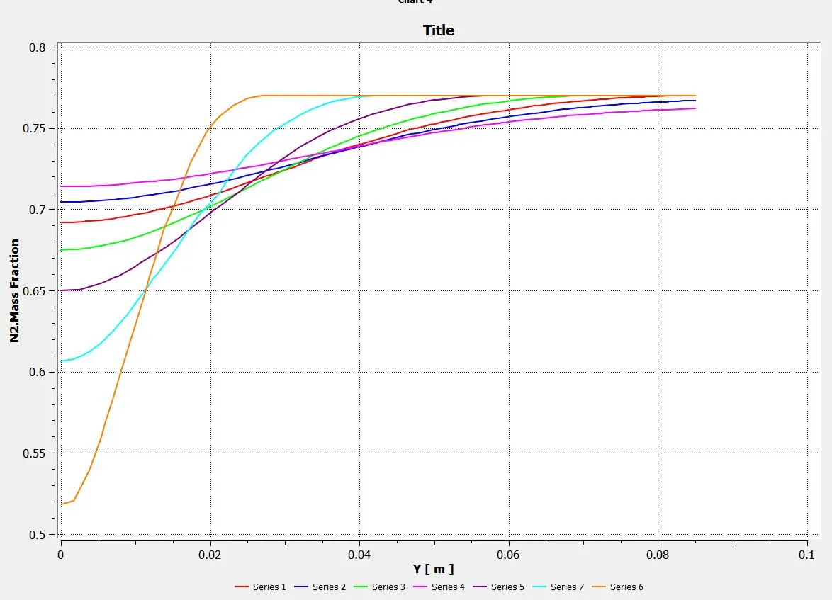
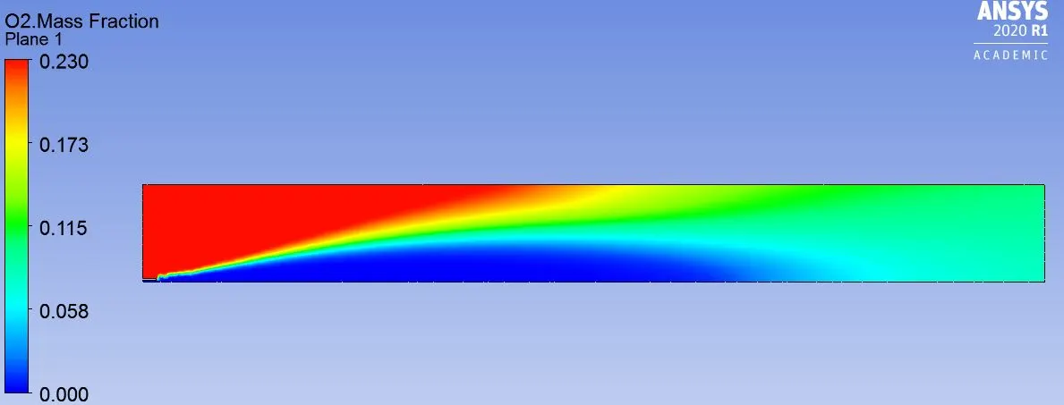
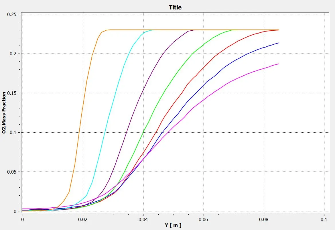
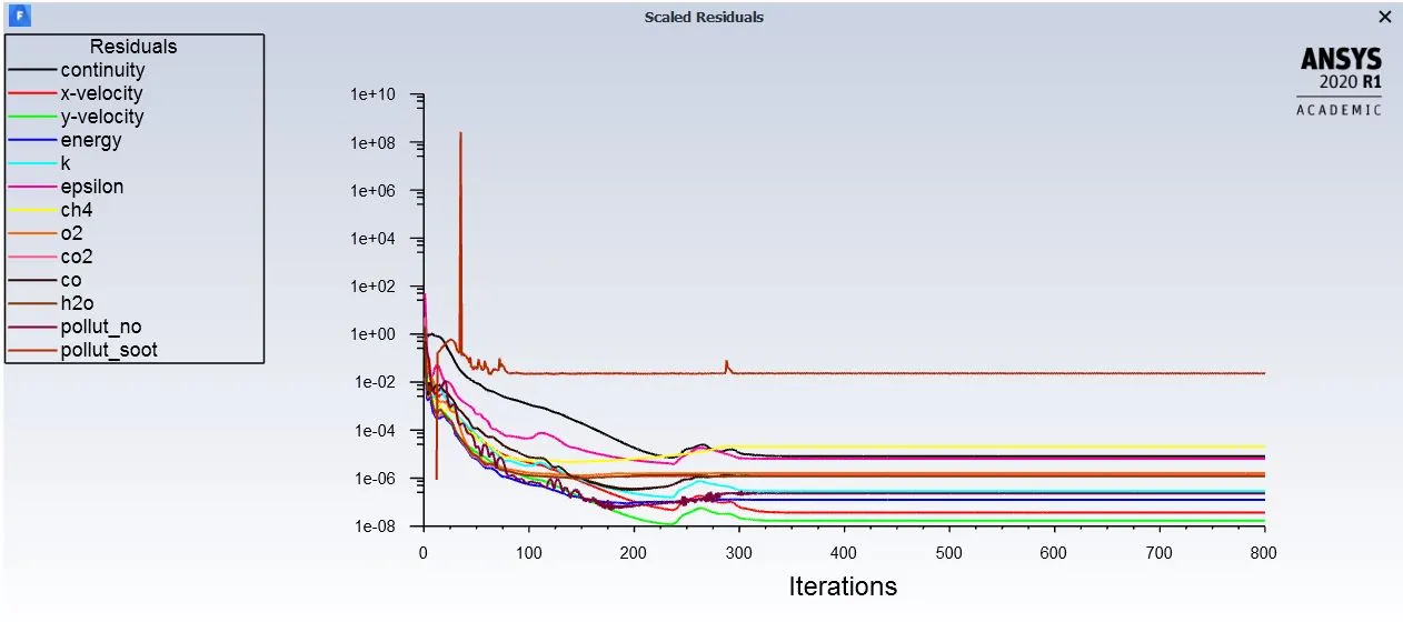
The Simulaton is done is two parts. For both the parts the simulation is ran for 800 iterations. To observe the emmision of CO2, H2O, CH4, N2, O2, NOx Chart were also made.
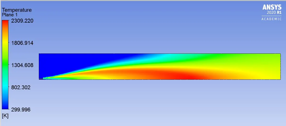
Part 1
Part 2
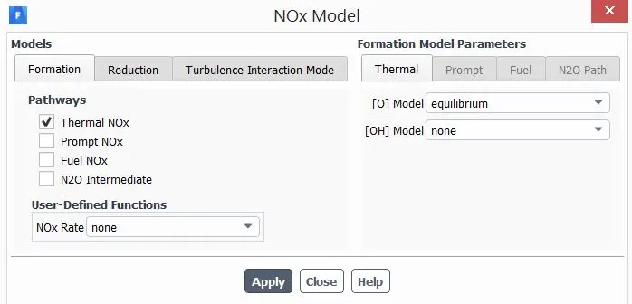
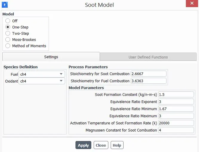
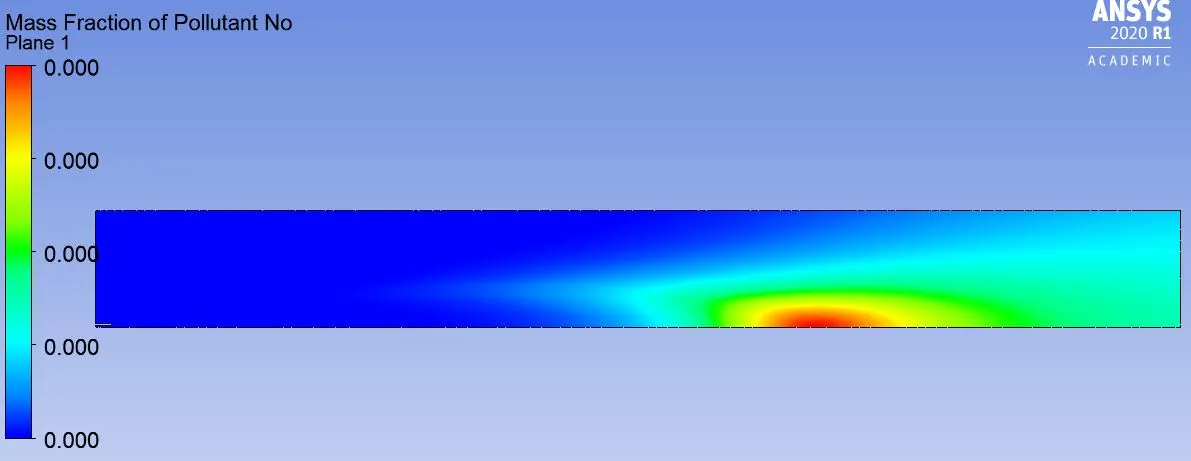
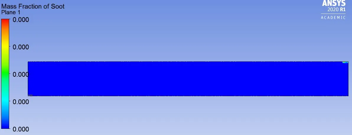
For the second part of the simulation the Mixture Material is set to Methane-air (2-step). Also the NOx model and soot model(one-step model) are enable for the simulation.Rest of the settings are same.
Result
The maximum temperature achived during the combustion was 2309 K. Also the formation of the species like Co2,N2 & H2O were observed is the charts. The data is taken from 0.1m to 0.4m away from the inlets.