Simulating combustion on an axi-symmetric geometry
Aim:
- To perform a combustion simulation on the combustor model and plot the variation of the mass fraction of the different species’ in the simulation using line probes at different locations of the combustor.
- To add the water content in the fuel from 5% to 30% by mole and observe the effect of it on the results.
Theory:
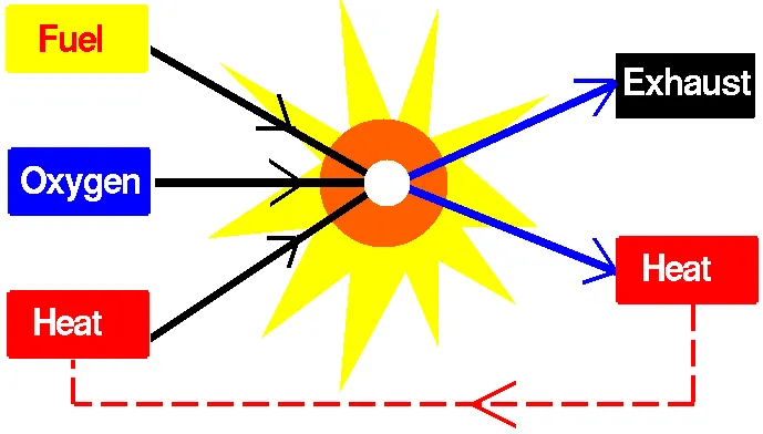
To move an airplane or a model rocket through the air, we must use a propulsion system to generate thrust. Different types of aircraft use different types of propulsion devices, but all aircraft rely on some type of engine to generate power. Rocket engines, internal combustion, or piston engines, and jet engines all depend on the burning of fuel to produce power. Burning fuel is called combustion, a chemical process that we study in middle or high school.
Because combustion is so important for aircraft and rocket propulsion, we will review the fundamentals. Combustion is a chemical process in which a substance reacts rapidly with oxygen and gives off heat. The original substance is called the fuel, and the source of oxygen is called the oxidizer. The fuel can be a solid, liquid, or gas, although for airplane propulsion the fuel is usually a liquid. The oxidizer, likewise, could be a solid, liquid, or gas, but is usually a gas (air) for airplanes. For model rockets, solid fuel and oxidizer is used.
During combustion, new chemical substances are created from the fuel and the oxidizer. These substances are called exhaust. Most of the exhaust comes from chemical combinations of fuel and oxygen. When a hydrogen-carbon-based fuel (like gasoline) burns, the exhaust includes water (hydrogen + oxygen) and carbon dioxide (carbon + oxygen). But the exhaust can also include chemical combinations from the oxidizer alone. If the gasoline is burned in air, which contains 21% oxygen and 78% nitrogen, the exhaust can also include nitrous oxides (NOX, nitrogen + oxygen). The temperature of the exhaust is high because of the heat that is transferred to the exhaust during combustion. Because of the high temperatures, exhaust usually occurs as a gas, but there can be liquid or solid exhaust products as well. Soot, for example, is a form of solid exhaust that occurs in some combustion processes.
During the combustion process, as the fuel and oxidizer are turned into exhaust products, heat is generated. Interestingly, some source of heat is also necessary to start combustion. Gasoline and air are both present in your automobile fuel tank, but combustion does not occur because there is no source of heat. Since heat is both required to start combustion and is itself a product of combustion, we can see why combustion takes place very rapidly. Also, once combustion gets started, we don't have to provide the heat source because the heat of combustion will keep things going. We don't have to keep lighting a campfire, it just keeps burning.
To summarize, for combustion to occur three things must be present: a fuel to be burned, a source of oxygen, and a source of heat. As a result of combustion, exhausts are created and heat is released. You can control or stop the combustion process by controlling the amount of the fuel available, the amount of oxygen available, or the source of heat.
Geometry and mesh:
The 3D geometry consists of a fuel injector, air inlet, and casing as shown below. Since performing combustion simulation of the given 3D geometry is an expensive and time-consuming process, the given geometry is simplified into a 2D axisymmetric model.
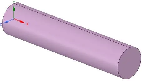

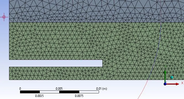
The 2D axisymmetric model is generated. Additional enclosures are provided so as to refine the mesh near the fuel inlet. Share topology is enabled to transfer data between the enclosures. Different parts of the geometry were named(air inlet, fuel inlet, wall, axis, outlet) so that the boundary conditions can be applied easily.
In the meshing module, the mesh is generated on the 2D geometry using the all triangles method. The mesh element size for the outer, middle, and inner enclosure is 5e-3m, 1e-3m, and 5e-4m respectively. There were a total of 22045 nodes and 43266 mesh elements once the resultant mesh is generated.

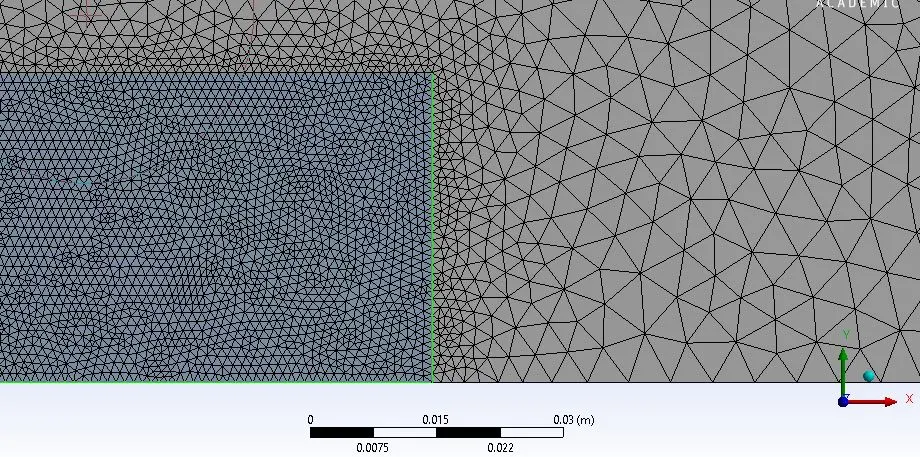
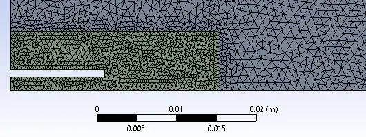
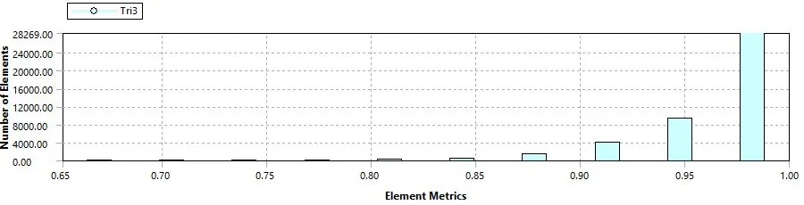
The resultant mesh had a good mesh quality, with the majority of the mesh elements having mesh quality greater than 90%
Setup:
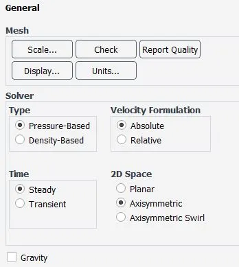
1. The problem is solved using the pressure-based, steady-state solver. In the general settings, the 'axisymmetric' option is enabled. By enabling this option, the system assumes that the properties remain the same in the radial direction of the combustion chamber.
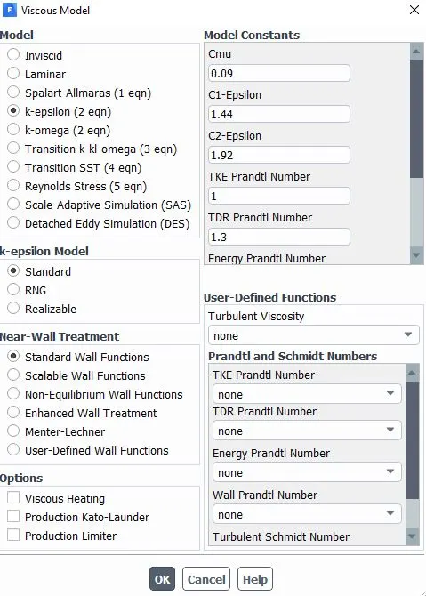
2. The standard K-epsilon viscous model with standard wall functions is chosen to solve the problem.
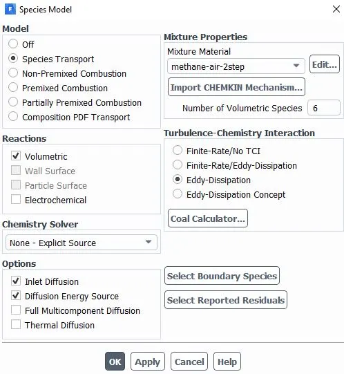
3. The species model is enabled, and the species transport model is chosen. Volumetric reactions are enabled. Methane air 2 step is chosen as the mixture material. Eddy-dissipation is chosen as the turbulence chemistry interaction.
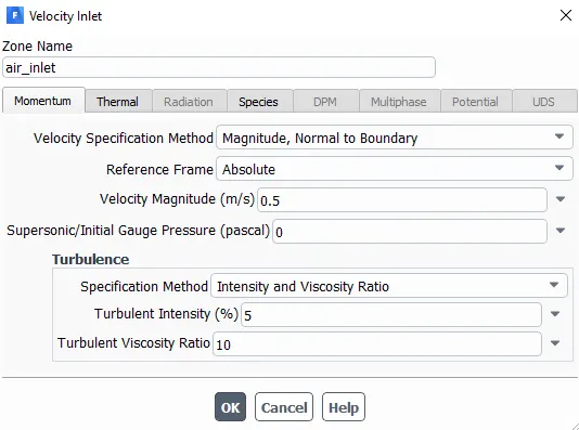
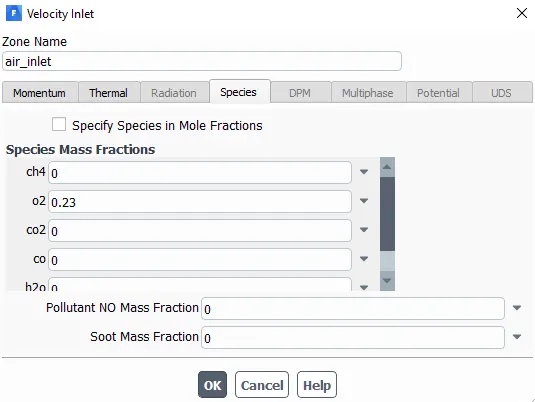
4. The boundary conditions at the air inlet are provided. Velocity magnitude= 0.5m/s, temperature= 300K, and the mass fraction of O2 is given as 0.23 in the species tab.
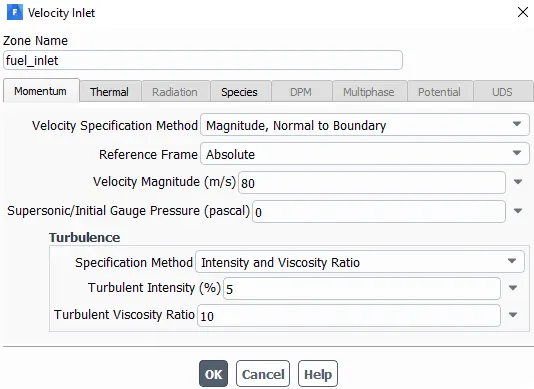
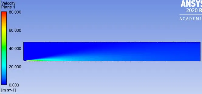
5. The boundary conditions at the fuel inlet are provided. Velocity magnitude= 80m/s, temperature= 300K. In the species tab, the mass fractions of the fuel and water are provided with the parametric input. By doing so a parametric study can be conducted on the effect of water content in fuel to the by-products produced. Initially, the mass fraction of CH4=1, and for H2O=0.
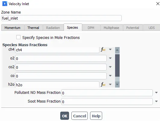
6. The boundary condition provided at the outlet is pressure outlet with the gauge pressure being 0Pa, and the walls are provided with a stationary-wall, no-slip boundary condition.
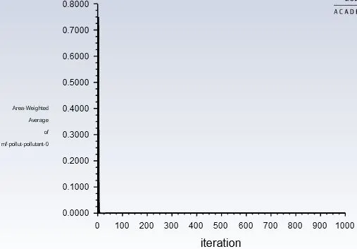
7. The NOx(thermal NOx) and soot(one-step) model was enabled so simulate the mass fraction of pollutants produced due to the process of combustion.
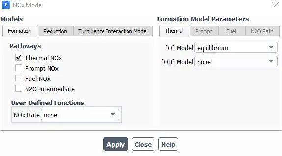
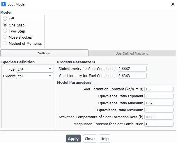
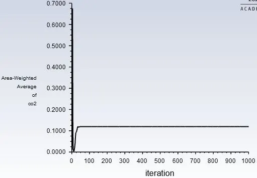
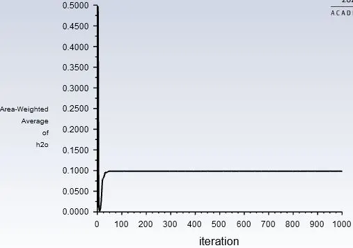
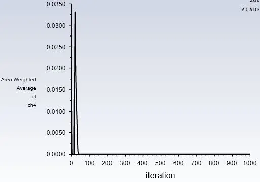
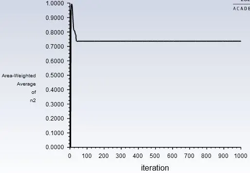
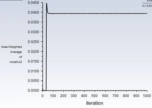
8. The area-weighted average of the mass fractions of CO2, H2O, CH4, N2, O2, NOx emissions, and soot formation was plotted and were set as output parameters to simulate its variation with the water content in the fuel.
9. The solution was initialized using hybrid initialization, and the solution was run for 1000 iterations.
Solution:
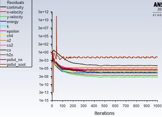
The solution was run for 1000 iterations, and the solution report of mass fractions of CO2, H2O, CH4, N2, O2, NOx emissions, and soot formation was calculated at the outlet and the solution report plots are given below:
CO2:
H2O:
CH4:
N2:
O2:
NOx emissions:
Soot formation:
Post-processing:
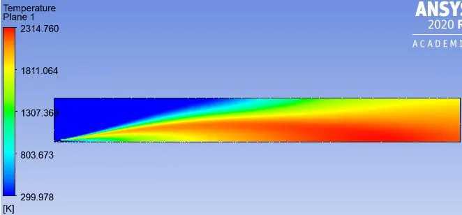
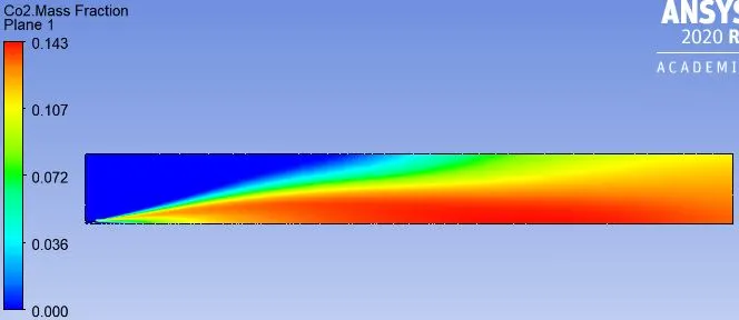
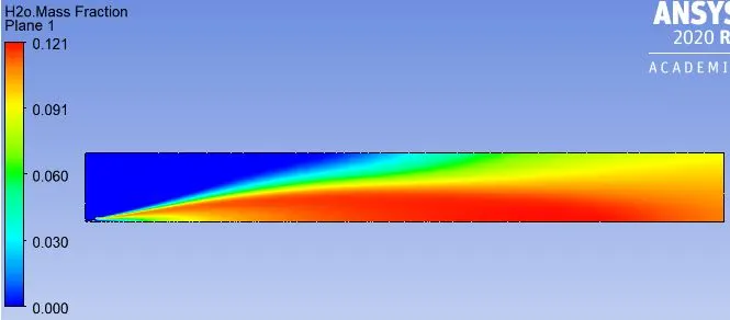
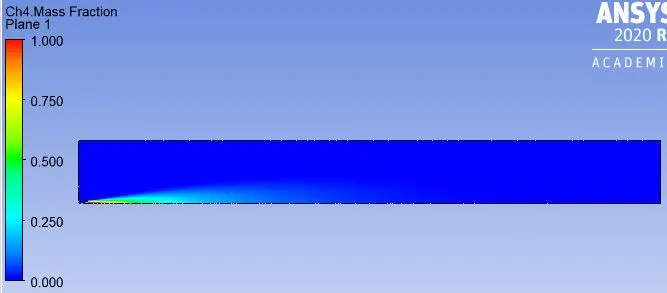
The following contours are visualized in the post-processor
Velocity:
Temperature:
Mass fraction of CO2:
Mass fractions of H2O:
Mass fractions of CH4:
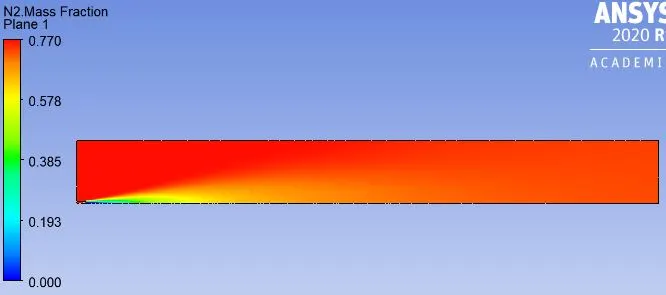
Mass fractions of N2:
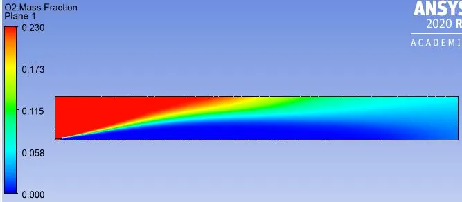
Mass fractions of O2:
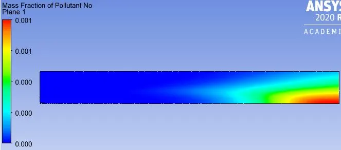
Mass fractions of NOx emissions:
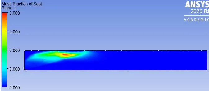
Mass fractions of soot formation:
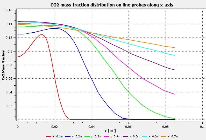
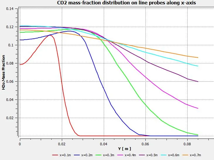
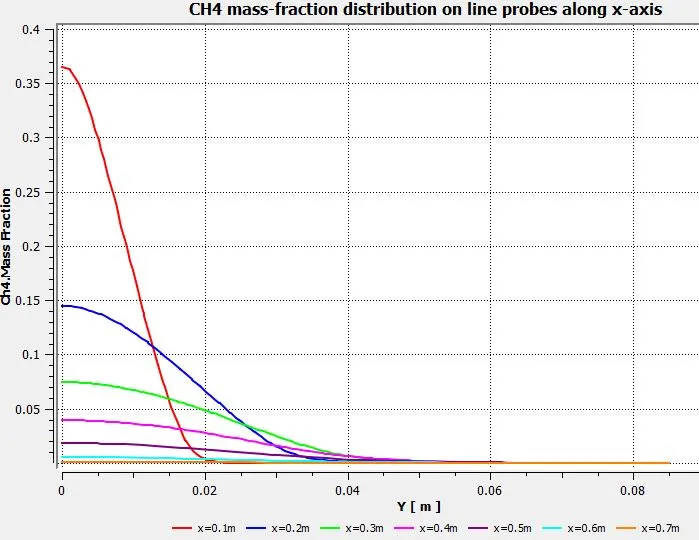
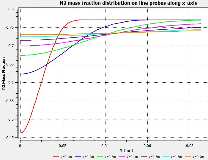
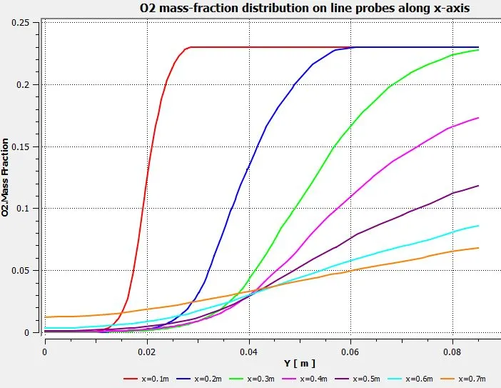
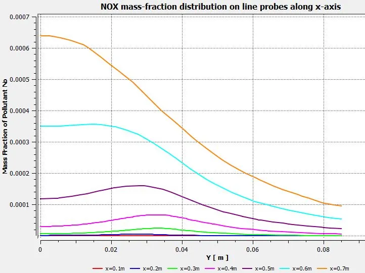
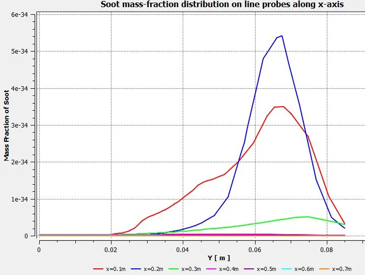
Line probes are drawn at a distance of 0.1m from each other, and the variation of the mass fractions of CO2, H2O, CH4, N2, O2, NOx emissions, and soot formation along its length is simulated.
CO2:
H2O:
CH4:
N2:
O2:
NOx emissions:
Soot formation:
Parametric study:
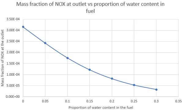
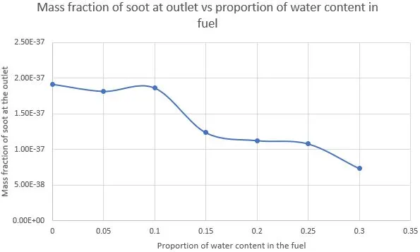
The Nox and soot are getting formed as a result of combustion. Such formation has harmful effects on the environment and humans. The stringent government norms also demand the least formation of Nox and soot. To satisfy these requirements, we need to check the effect of adding the water in the fuel. Here, the water content is added in the fuel from 5% to 30% by mole, and its effect is observed on the magnitude of emissions produced.
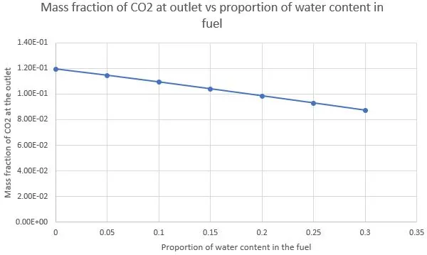
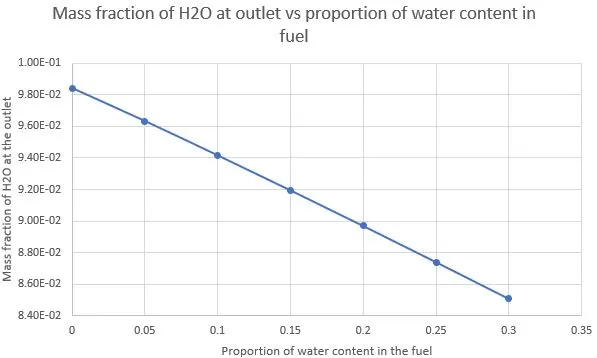
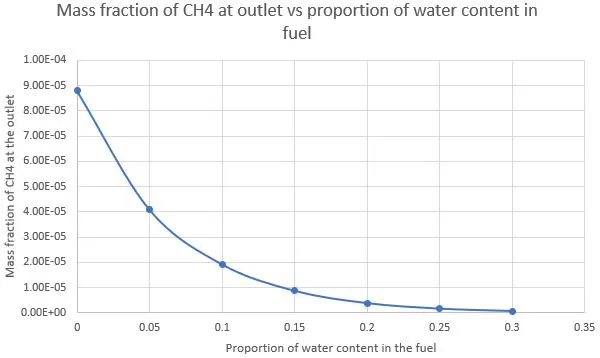
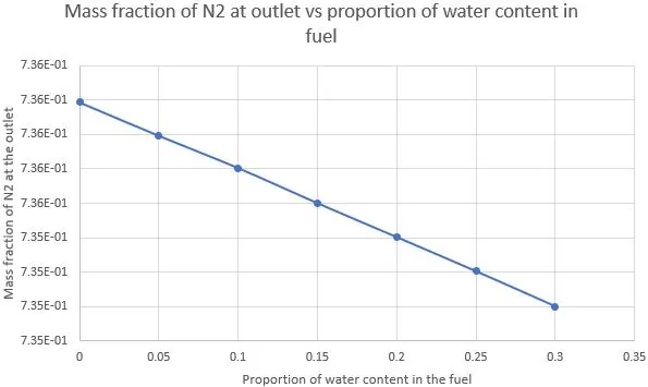
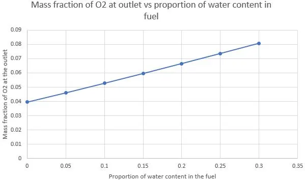
To perform this simulation, the best and quickest method is to perform a parametric study. Here the mass fractions of CH4 and H2O are taken as input parameters, and the proportion of H2o is increased from 0% to 30% gradually. The mass fractions of CO2, H2O, CH4, N2, O2, NOx emissions, and soot formation calculated at the outlet are taken as the output parameters.
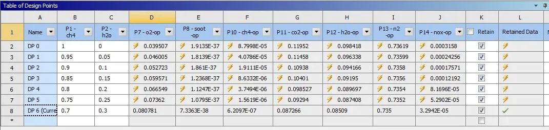
The variation of the mass fractions of CO2, H2O, CH4, N2, O2, NOx emissions, and soot formation at the outlet of the combustion chamber with the water content is given below
CO2:
H2O:
CH4:
N2:
O2:
NOx emissions:
Soot formation:
Conclusions:
- During the combustion process, a lot of heat is generated, due to which the temperature of the fluid domain increases substantially. This temperature distribution becomes more even near the outlet of the combustion chamber. This is due to diffusion.
- From the line probe plots, we can see that more even distribution of mass fractions of different elements is obtained near the outlet. This is also caused due to diffusion.
- From the parametric study, we can see that with the addition of water in the fuel, lesser pollutants/emissions are produced. Except for the mass fraction of O2 which increases with the increase in the percentage of water in the fuel, all other elements show the negative trend.
- Hence, to reduce the pollutants produced due to the combustion of fuels, the addition of water by some means at a particular proportion will help in reducing the emissions and soot formation considerably.