Challenge 9
Ans 1
PIER
Diameter of pier, D = 2.0 m
Area of the pier = π/4 x D2 = 3.142 m2
Density of concrete = 25 kN/m3
Dead load of the pier/m = 25 x 3.142 = 78.54 kN/m
For a length of 30.0 m, dead load = 2356.2 kN
PIER CAP
Volume of pier cap = 35 m3
Dead load of the pier cap = 35 x 25 = 875 kN
Assuming the length of the pier cap also to be 10.0 m,
Dead load of the pier cap/m = 875/10 = 87.5 kN/m
Ans 2
To protect the piers from vehicular collision directly, there are safeguarding structural RCC systems built all around the pier to take the impact of the collision.
- At the base of the RCC pier, a rectangular or circular system is designed and built in line with the shape of the pier such that the section of the RCC pier is strengthened at its base.
- Auxillary base structure built at some offset to the pier to safeguard direct impact of the vehicle. This will in no way guarantee that the vehicle will not collide with the main pier. However, after the initial impact there will be considerable dissipation of energy which is almost like impulse loading.

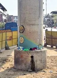
In the case of piers constructed on a water body, provision of fenders, also called as dolphins, are constructed so that the ships navigating through these spans do not directly hit the main pier. In many cases, barges are used even during the construction of a bridge and are susceptible to collision with the under-construction bridge piers. Here, the barge impact needs to be considered for designing the pile cap.
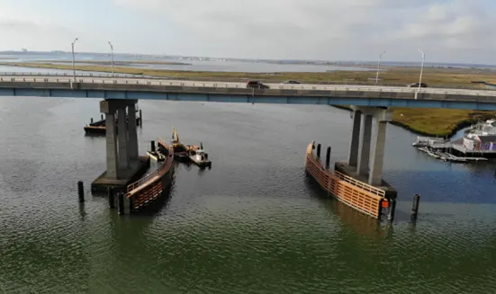
There may be cases where the DBR itself states design criteria defining the load case to be considered for design of the pier / pile cap. For instance, barge impact load on a pile cap is a totally different load as compared to the permanent loading of the bridge.
As a viaduct bridge designer, it is very important to understand that any damage to the pier due to a collision, however rare, shall lead to damage to various extents depending on the impact and mass of the vehicle. It can even lead to a catastrophic collapse of the bridge if not attended to properly.
Ans 3
Axle loads are already stated in the DBR of a metro viaduct. These axle loads and their spacing are applied as moving loads on a model to get the results. Typically, on one span of 27.0 m girder one bogie and a half is present at a time. Below is a typical pic of the loads and their spacing.
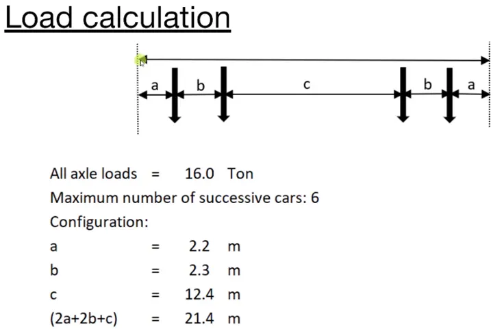
The arrows indicated in dark are the locations of the axle loads and are generally taken as 16 T with total c/c between bogies = 21.4 m
Ans 4
A rigid element present in between the pier and the piles is called the pile cap. It is a structural element that transfers the loads from the pier to the piles in the form of axial forces.
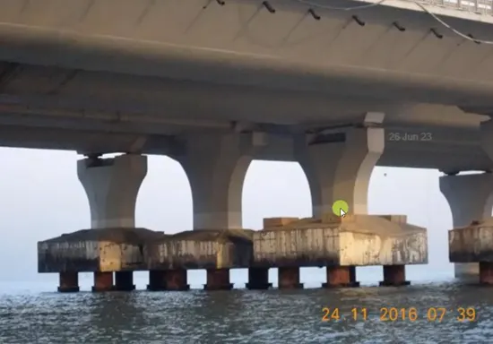
Significance of the pile cap: (STRUCTURAL)
- Transferring all the loads from the piers to the piles
- Converting the various forms of loads like moments (longitudinal and transverse, bi-directional shear and vertical loads and transferring it to the piles in the form of tension and compression
- To carry out the above load transfer, it must be a rigid structure.
Significance of the pile cap: (FUNCTIONAL)
- Pile caps provide flexibility in construction. For instance, if the pier is to be placed directly on piles and say that piles are constructed with a certain allowable eccentricity, then the pier would also be constructed with that eccentricity.
- This means that the pier cap and bearings shall also be constructed eccentric and in the end the superstructure alignment would not be where we intend it to be.
- For this purpose, pile caps are designed, and they provide a firm base such that the piers can be constructed at their exact location.
- Normally, a pile cap covers the entire area of the group of piles and 150 mm offset beyond it and the plan dimensions are decided accordingly. This is to cater to any minor tilt or shift during the casting of the pile.
- Moreover, pile caps provide a firm base and a firm working platform for the construction activities of the bridge like pier, pier cap and superstructure. The formwork arrangement can be easily accommodated on this sufficiently large base.
Ans 5
Monopiles: A single pile on which the pier is constructed directly without the need to design a pile cap.
|
Advantages & Disadvantages of Monopiles |
|
|
Fast construction of single pile |
Construction errors like tilt in pile cannot be adjusted |
|
Construction of multiple piles can be avoided |
Pier must be shifted to be aligned with the pile |
|
Pile cap construction activity removed |
Load flow from pier to pile is by shear and flexure |
|
Accurate construction required with less margins |
|
|
More material required due to larger diameter pile |
|
|
Special equipment required for construction of larger diameter pile need to be deployed |
|
|
Skilled personnel required for construction of monopile |
|
Ans 6
Assumptions made for designing of pile cap and pile:
- Pile cap is designed by bending theory for shear and flexure if the c/c distance between the piles is large. For instance, if c/c between piles is 4d and depth of pile is 1.5d, (where d is the diameter of the pile) then load cannot flow 45 degree between piles leading to flexure in the pile cap.
- Pile cap is designed by strut and tie theory if distance between piles is small and force flows through tension and compression of the pile cap. For instance, if c/c distance between piles is 2d and depth of pile cap is 1.5d, (where d is the diameter of the pile) then the load from the pier flows directly through compression and tension in the pile cap and there is no scope for generation of flexure.
- Strut and tie theory is used when there is a 4 pile group and for pile group having more than 4 piles we use bending theory.
- Edge distance from face of pile is assumed as 150 mm to accommodate tilt and shift and provide sufficient lapping of dowel bars coming out from piles.
- Density of soil is assumed as 20 kN/m3.
- Density of concrete is assumed as 25 kN/m3.
- Distance between top of pile cap to the ground level ~ 500 mm to ensure that the pile cap is fully embedded in the ground and it does not interfere with the traffic movement.
- Depth of pile cap = 1.5 d, where ‘d’ is the diameter of the pile.
- Pile design is based on specific geotechnical assumptions of bore hole data available.
Ans 7
Following data is typically used for calculating the forces and moments in a pile cap section by bending theory:
SOFTWARE: Any standard analysis software can be used for modelling the pile cap.
GEOMETRY & BOUNDARY CONDITIONS: Centre to centre of piles is known and those are used as supports for the modelling of the pile cap as a beam element in 2D or a plate element in 3D.
LOADS:
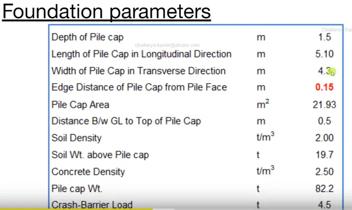
With the preliminary assumption of depth of 1.5 times diameter of pile, plan dimensions as per the pile centres and offsets assumed, we can get the self-weight of the pile cap.
Load of surcharge soil can also be applied considering the volume of the soil present on top of the pile cap i.e. the plan dimensions of pile cap x depth of soil x density of soil
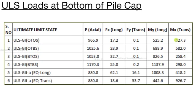
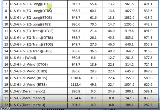
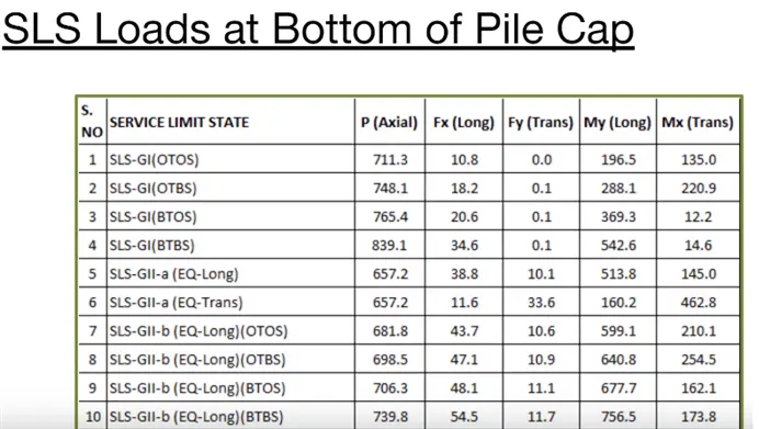
Major loads from the bridge transferred to the pile cap at the base of the pier are Axial forces, Shear and bending moments in both longitudinal and transverse directions P, Fx and Fy, Mx and My respectively.
After application of all basic external and internal loads, load combinations are added in both SLS and ULS case for checking the serviceability and strength criteria of the pile cap. (See figures below)
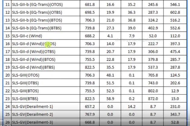
After obtaining values for maximum shear and bending forces on pile cap, we proceed for the design of pile cap wherein standard section check software can be used.
Another option is designing it by first principle. We first locate the neutral axis of the section by equating the concrete compression forces to the steel tensile forces.
Moment of resistance of the tension zone is given by Mud = 0.87*fy*Ast*(d-0.42Xu)
Moment of resistance of the compression zone is given by Mud = 0.36*fck*b*Xu*(d-0.42Xu)
Mud minimum of above is the capacity of the section and should be greater than applied design moments.
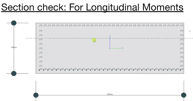
Crack width is calculated with the help of standard set of formula and checked as per relevant codes.
Based on the stresses in concrete Fc, stresses in steel Fy, crack width limit and M/Mu ratio, a design engineer can optimize the depth/reinforcement/spacing of rebars and recheck the values with new iterations so that a most optimized section is obtained.