Challenge 9
Aim:
Q1)Explain in detail the steps involved in calculation of the loads considered in piers.
Answer:-
- Pier is the compression member of the bridge.
- They support the span (superstructure) of the bridge by transferring the load to the foundation.
- They are subjected to massive loads like
- Bi-axial moment in both longitudinal and transverse direction.
- Axial loads and shear force.
Following are the Loads considered in piers:
- Dead Load:
- This load majority comprises of selfweight of girder,pier caps and pier.
- Superimpose Dead Load:
- This load majority comprises the weight of track plinth, rail, cables, cable trays, cable trough, handrails, parapets etc.
- Live Load:
- This load comprises the train (rolling stock) live load that runs on the superstructure.
There are four cases:
a. One Track One Side Loaded (OTOS)
b. One Track Both Side Loaded (OTBS)
c. Both Track One Side Loaded (BTOS)
d. Both Track Both Side Loaded (BTBS)
- Breaking Load:
- This load comes into play when the train applies brake while moving.
- It is taken as 18% of the unfactored vertical load.
- Traction Load:
- This load comes into play when the train starts to accelerate from rest.
- It is taken as 20% of the unfactored vertical loads.
- Centrifugal Force:
- This load acts on curved spans.
- It shall be calculated with the actual maximum allowed speed of the train in a curve according to the planned radius of curvature.
- Coefficient of CF = `V^2/127 xR`
- Wind Load (without Live Load):
- This load comes into play when wind exerted load on the structure.
- In this case the wind pressure will be very high making it quite difficult to move the live load.
- Wind Load (with Live Load):
- This load comes into play when wind applied forces on the structures.
- In this case, the wind pressure will be normal allowing the movement of live load.
Vz= Vb x K1 x K2 x K3
- where Vb(m/s) is the regional basic wind speed.
- Earthquake Load (in Longitudinal Direction):
- This load comes into play during an earthquake when the structure vibrates in the longitudinal direction.
- Live Load is not considered in the case as vibration doesn't have any impact on the live load as it rolls away.
- Earthquake Load (in Transverse Direction- with Live Load):
- This load comes into play during an earthquake when the structure vibration is in the transverse direction.
- Live Load is considered in the case as the live load will be restrained to move in the transverse direction and would thus vibrate along with the structure.
- Earthquake Load (in Transverse Direction- without Live Load):
- This load comes into play during an earthquake when the structure vibrates in the transverse direction.
- In this case the live load will not be present on the structure.
- LWR Force:
- The "Long Welded Rail" force acts on the structure to stress generated in the rail.
- It is generated by the expansion/ contraction of rail due to an increase/ decrease in temperature.
- LWR force is considered to be 0.8 t/m/track.
- Derailment Load:
- This load comes into play when the live load gets derailed.
- In this case the live load may get off the track & slide to the edge of the structure or the live load may derail and topple on the edge.
Q2) Elaborate the design codal provisions for piers of metro viaducts.
Answer:-
Shear Checks
Shear Enhancement Factor:
- d= 1+0.05P / Ac
where,
- P = ultimate axial load in newtons
- Ac=area of entire column in mm^2
- fck=characteristics compressive strength of concrete.
According to table 15 of IRS-CBC 1997 ultimate shear stress in concrete as per percentage area of tension reinforcement and grade of concrete.
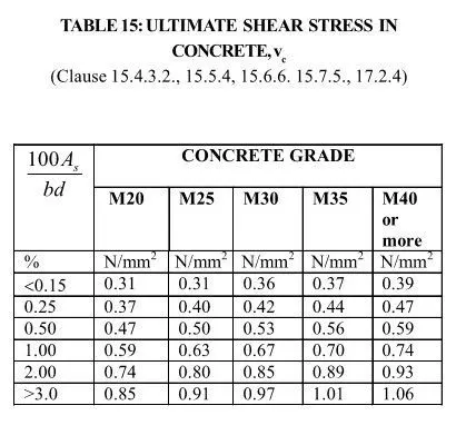
Ultimate shear stress, Vc= 0.767 N/mm2
Depth factor, S= 0.799
Enhanced Ultimate Shear Strength of concrete, S x Vc x d= 0.715 N/mm2
Shear reinforcement is required if V>S x Vc x d
If V <= Vc x S, Asv=0.4 x b x sc/0.87xfy
If V>S x Vc, Asv=b x Sv x (V+0.4-SVc)/0.87xfy
where,
-Asv= C/S area of all legs of the stirrups/links at a particular C/S.
-Sv= Spacing of the stirrups along the member.
-B= Width of the section.
Confining Reinforcement (for circular section)
Ash= 0.09 x S x Dk x (Ag/Ac-1) x Fck/fy
or
Ash= 0.024 x S x Dk x fck/fy
Take maximum value from above
where
- Concrete grade (fck)
- Reinforcement grade (fy)
- Dia of the pier (D)
- Clear cover on either side (c)
- Dia of pier core (Dk)
- Area of concrete core (Ac)
- Gross area of pier section (Ag)
- Pitch of spiral (S)
P-delta effect
Effective Length Calculation
- Diameter of the pier, d
- Cantilever Height of pier, Lo
- Effective Height of pier, Le (=2.3 x Lo)
Additional moment due to slenderness ratio effect
Slenderness ratio, Le/d (as per Cl 15.6.1.1 of IRS CBC)
As per the below clause
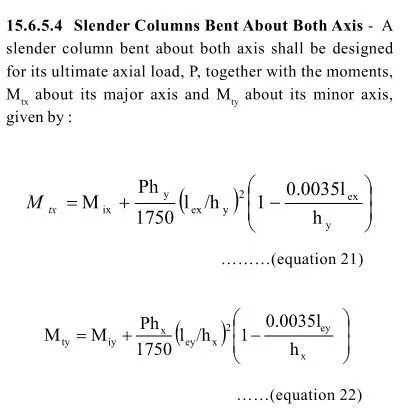
Additional Moment, Me= P x e