Challenge 9
CHALLENGES- 9
- Explain in detail the steps involved in calculation of the loads considered in piers.
AIM:
Here i am going to explain about the steps involved in the calculation of the loads considered in the piers.
- Dead load of structure
Dead load of U- girder Dead load of pier cap
Density of concrete - 2.50 t/m³ volume of pier cap- 31.00
Cross-sectional area of U- girder - 2.173m² Dead load of pier cap- 31*2.5= 77.50 Ton
Dead load of 27m U-girder - 2.173*2.5*27= 146.7 ton
Dead load of pier
Area of pier ( circular pier diameter =1.7m)-2.27
Dead load of pier/m = 2.27*2.5=5.67 Ton
- superimposed dead load
Load due to SIDL - 2.20 Ton/m/track
SIDL of 27 m U- girder- 2.2*27= 59.40 Ton
- LIVE LOAD
- one track one side loaded (longitudinal direction)
- one track both side loaded (longitudinal direction)
- both track one side loaded (longitudinal direction)
4.both track both side loaded(longitudinal direction)
AXLE LOAD
- Braking load:
It is taken as 18 percent of the unfactored vertical loads.
- Traction load:
It is taken as 20 percent of the unfactored vertical loads
- since each track is supported by a single U - girder tractive force of one track and braking force of another track will be taken in athe same direction to produce the worst condition of loading
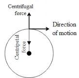
- CENTIRIFUGAL FORCE :
WIND LOAD
calculation of wind load is based on IS - 875(PART3) - 1987.
The design wind at height z is considered as fallow .
Vz= Vb.K1.K2.K3
Vb(m/s) Reginal basic wind speed taken 47 m/s for varanshi
GENERAL PARAMETERS Vb
total structure Height above ground H = 13.6m
Regional basic wind speed Vb = 47m/s
probability factor = 1.07
Terrain Height and structure size factor K2 = 0.856 ASSUMING CATEGORY 3 TERRAIN
TOPOGRAPHY FACTOR K3= 1.0 class c structure
design wind speed at height z, Vz
Vz= Vb. K1. K2.K3= 43.1m/s
wind pressure = 1112.41 N/m²
Pz= 0.6×Vz²= 0.113 t/m²
- LOAD FROM SUPERSTRUCTURE
Over width of both U- girder combined b = 10.15m
contributing length of superstructure l= 27.00m
Total Depth of superstructure d = 1.87m
Height of live load above U- girder h= 3.232m
Transverse wind load without live load = 50.49m
Project area of structure A1 = l×d = 5.73m
PD= Pz×At = 15.62m
Acting @above pier bottom
Transverse wind load with live load
Project area of structure A1= l×d+h = 137.75m
PD= PZ×At = 15.62m
Acting @above pier bottom = 14.80m
Vertical wind load Pv =
Plan Area of superstructure Av= b×l = 274.05m²
Pv= Pz×Av = 31.08t
LOAD ON SUBSTRUCTURE
PIER CAP
Width of pier cap ( conservation)b = 3.10m
length of pier cap d = 9.60m
height of pier cap h = 2.00m
height of pier cap above ground h = 11.55m
wind in longitudinal direction
Ratio a/b=d/b = 0.32
force coefficient Cf = 1.22
projected area of structure At= h×d= 19.20m³
wind force F= Cf×Pz×At= 2.65t
Acting @above pier bottom = 11.05m
wind in transverse direction
Ratio a/b =b/d = 3.10
force coefficient Cf = 1.04
Projected Area structure A1 =h×b = 6.20m³
wind force F = 0.73t
Acting@above pier bottom = 11.05m
PIER
Diametre of pier , b= 1.70m
Height of pier above Ground h = 9.55m
wind in longitudinal /transverse direction
Ratio height /Breadth = h/b = 5.62
force cofficient Cf = 0.80
projected area of structure A1 = h×b = 16.24m²
wind force F = 1.47t
Acting@above pier bottom = 5.28m
SEISMIC ACCELERATION : Ah= (z/2)*(l/R)*(sa/g) where:
Ah= horizontal seismic coefficent to be considered in design
Z= zone factor = 0.16( for varanasi region)
I= importance factor= 1.50
R= response Reduction factor
=4 for pier
sa/g being computed as per irc 6:2017 for medium soil sites
mathematics expressions are:
sa/g=1+15T for 0.0< T <0.10
sa/g=2.5 for 0.10<T<0.55
sa/g = 1.36/T for 0.55<T<4.00
2.Elaborate the design codal provisions for piers of metro viaducts.
AIM
HERE I AM GOING TO ELABORATE THE DESIGN CODAL PROVISION FOR PIER OF METRO VIADUCTS
THIS CODAL PROVISION FOR R.C.C PIER AND PRESTRESS CONCRETE PIER CAP IN THIS WE FIND OUT HOW MANY CONCRETE REINFORCEMENT AND PRE STRESSING TENDON NEEDED WE CALCULATE
ACCORDING TO CODAL PROVISION FCK THAT MEANS COMPRESSIVE STRENGTH OF STRUCTURE .
* TABLE 11 CLAUSE 10.2.2 OF IRS CBC STRESS LIMITATIONS FOR THE SERVICELIBLITY LIMIT STATE.
MATERIAL TYPE OF STRESS UNDER DESIGN LOADING TYPE OF CONSTRUCTION
R.C.C PSC
CONCRETE TRIANGULAR OR MEAR TRIANGULAR COMPRESSIVE STRESS 0.50FCK 0.40FCK
UNIFORM OR NEAR UNIFORM COMPRESSIVE STRESS (E.G Y
DUE TO AXIAL LOADING 0.38FCK 0.30FCK
REINFORCEMENT COMPRESSION TENSION 0.75FY NA
PRE-STRESSING TENDONS TENSION NA DEEMED TO SATISFIED BY
16.8.1
- TABLE 10 ( CLAUSE 10.2.1) OF IRS CBC DESIGN CRACK WIDTH THE VARIOUS EXPOSURE CONDITIONS
EXPOSURE CONDITION DESIGN CRACK WIDTH IN MM
- MODERATE _ 0.20
- SERVERE _ 0.10
- EXTREME _ 0.10