Challenge 8 Flattening & Forming the Metal Bracket II Using NX CAD
TITLE: Flattening & Forming the Metal Bracket II Using NX CAD
- Report on what's Neutral Data File? What does it mean? Where it's used?
The neutral file is one of the choices of CAD data exchange. so, let me first explain what's CAD data exchange. CAD Data Exchange CAD data exchange could be a modality of information exchange accustomed translate data between different software (CAD) authoring systems or between CAD and other downstream CAD systems. Many companies use different CAD systems internally and exchange CAD data with suppliers, customers, and subcontractors. Transfer of data is important so that, as an example, one organization will be developing a CAD model, while another performs analysis work on the the same model; at the identical time, a 3rd organization is to blame for manufacturing the merchandise. The CAD systems currently available within the market differ not only in their application aims, user interfaces, and performance levels, but also in data structures and data formats therefore accuracy within the data exchange process is of paramount importance and robust exchange mechanisms are needed. The exchange process targets primarily the geometric information of the CAD data but it also can target other aspects like metadata, knowledge, manufacturing information, tolerances, and assembly structure. There are three options available for CAD data exchange: direct model translation, neutral file exchange, and third-party translators. Now we all know what's CAD Data Exchange, so let's try to understand more about Neutral record.
Neutral Data File: -
Neutral file exchange uses an intermediary-neutral format to translate data between CAD systems. This method starts from a pre- processor embedded within the original CAD system, which generates the neutral file from the originating CAD format. The target CAD system post-processes the neutral file and converts it into the target native format. Some neutral formats are defined by standards organizations such as IGES and STEP while others are proprietary but still widely used and are considered quasi-industry standards
NEUTRAL FORMATS
- IGES (Initial Graphics Exchange Specification) - originated in late 1979 and was initially published by the American National Standards Institute (ANSI) in 1980 preceding the large-scale deployment of the CAD technology within the industry. This file format considers the product definition as a file of entities, with each entity being represented in an application-independent format After the initial release of STEP (ISO 10303) in 1994, interest in further development of IGES decline and Version 5.3 (1996) was the last published standard.
- DXF(Drawing exchange format) - developed by Auto desk in 1982 as their data interoperability solution between Auto CAD and otherCAD systems. The DXF is primarily 2D-based and its format could be a tagged data representation of all the knowledge contained in an Auto CAD drawing file, which implies that every data element within the file is preceded by an integer number that's called a gaggle code indicating the kind of following data element. As most commercial application software developers have chosen to support Auto desk's native DWG because of the format for AutoCAD data interoperability, DXF has subsided useful
- VDA-FS (Verband der Automobile industries - Flachenschnittstelle) - created by the German Association of the Automotive Industry in 1982 as an interoperability method for free-form surfaces. This format differs from other formats therein it only supports the communication of free-form curve and surface data with associated comments, but no other geometric or non-geometric Therefore, it's limited to representations by parametric polynomials, but this covers the good majority of free-form CAD systems. It includes Bezier, B-Spline, and Coons tensor product forms of surfaces and corresponding curves. The VDA-FS specification is released within the German Industrial Standard DIN 66301.
- PDES (Product Data Exchange Specification) - originated in 1988 under the merchandise Definition Data Interface (PDDI) study done by McDonnell Aircraft Corporation on behalf of the U.S. Air Force. PDES was designed to completely define a product for all applications over its expected life cycle, including geometry, topology, tolerances, relationships, attributes, and features necessary to completely define a component or assembly of parts. PDEs are often viewed as an expansion of IGES where organizational and technological data have been added. The later PDES contained IGES. the event of PDES under the guidance of the IGES organization and in close collaboration with the alignment of Standardization (ISO) led to the birth of STEP.
- STEP(ISO 10303 - Standard for the Exchange of Product model data) - the work with the ISO 10303 standard was initiated in 1984and initially published in 1994, with the target to standardize the exchange of product data between PLM systems. it's a comprehensive set of specifications covering many alternative product types and plenty of life cycle phases. STEP uses the neutral ISO 10303-11 format. also referred to as an EXPRESS schema EXPRESS defines not only the information types but also relations and rules applying to them. STEP supports data exchange data sharing and data archiving For data exchange STEP defines the transitory sort of product data that's to be transferred between a pair of applications. It supports data sharing by providing access to and operation on a single copy of the identical product data by quite one application, potentially simultaneously. STEP may additionally be accustomed support the development of the archive product data itself. STEP consists of several hundred documents called parts. once a year new parts are added or new revisions of older parts are released. This makes STEP the largest standard within ISO. The 200-series parts STEP are called Application Protocols (AP), with the particular parts directly associated with CAD systems:
- 203 (Configuration controlled 3D designs of mechanical parts and assemblies) - Mainly used for 3D design and products structure. A subset of AP214 but most generally used.
- 210 (Electronic assembly, interconnect, and packaging design) - CAD systems for the computer circuit board.
- 212 (Electrotechnical design and installation) - CAD systems for electrical installation and cable harness.
- 214 (Core data for automotive mechanical design processes) - How STEP is represented during a computer file for interchange.
- 238 (STEP-NC Application interpreted model for computerized numerical controllers) – CAD, CAM, and CNC machining process information.
- 242 (Managed model-based 3D engineering) – the merging of the 2 leading STEP application protocols, AP 203 and AP 214.
- Parasolid XT-part of the Parasolid geometric modeling kernel originally developed by Shape Data and currently owned by Siemens PLM Software.Parasolid can represent wire frame, surface, solid, cellular, and general non-manifold models. It stores topological and geometric information defining the form of models in transmitting files. These files have a broadcast format so applications can have access to Parasolid models without necessarily using the Parasolid kernel. Parasolid is capable of accepting data from other modeler formats. Its unique tolerant modeling functionality can accommodate and catch up on less accurate data. By using a Neutral file we can eliminate the matter of plenty number of translators and reduce it to just one translator by implementing a method of neutral file.
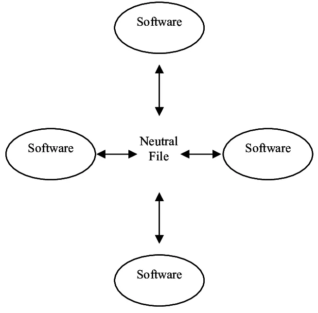
When this neutral file is employed cach CAD system needs just one preprocessor and one post-processor which forms one set of translators. illustrates the way the pre-processor imports the info into the system and also the post-processor outputs the file into the standard.
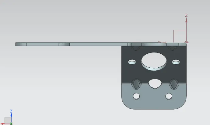
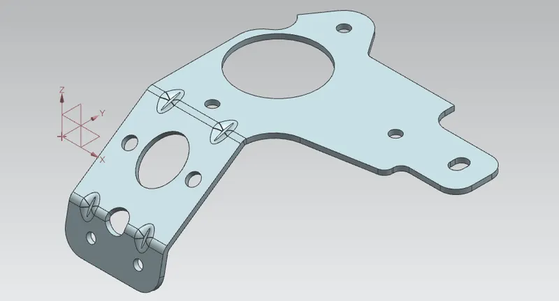
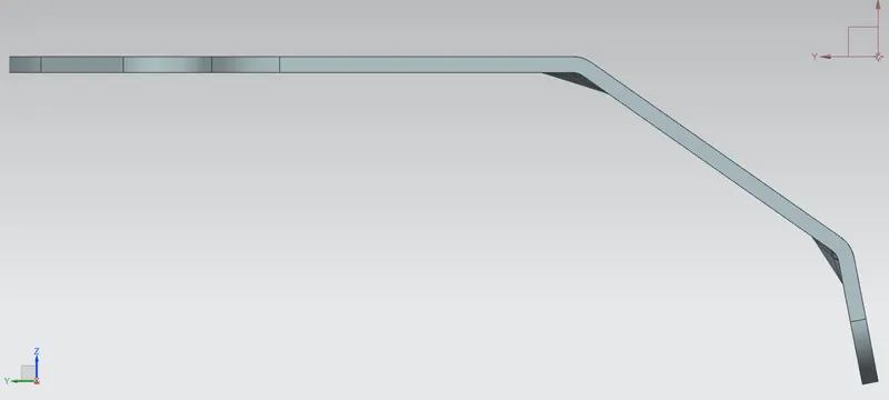
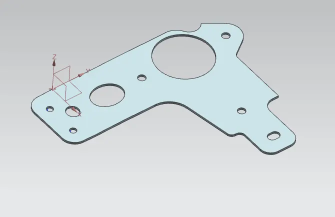
- Flattening & Forming the Metal Bracket II using NX CAD Objective:- To create a flattening bracket using NX CAD from the Dumb Body that is exported to otherformats like (STP., ages, dwg..).
Dumb Body: There is a desire to use CAD models within the optimization framework ... using either a dumb geometry, which could be a non-parametric CAD model from which ... Throughout this work, the feature parameters represent the input.
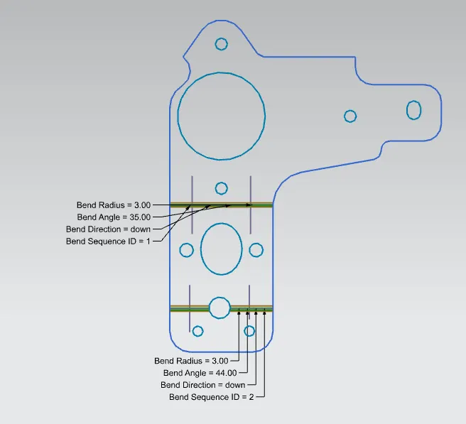
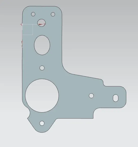
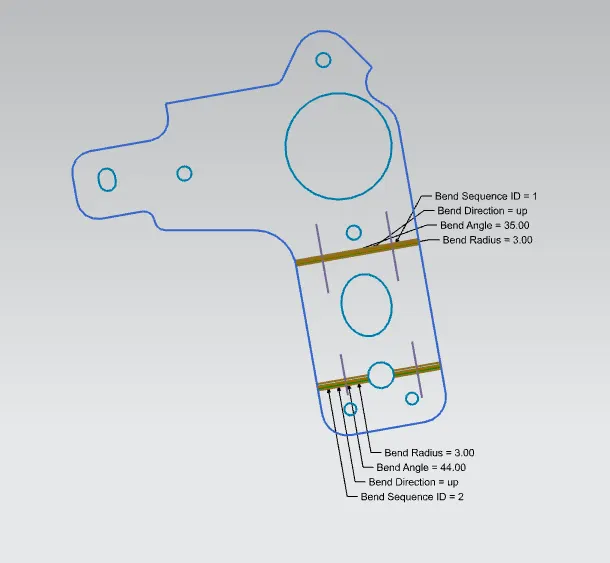
Introduction:- For Flattening the Bracket. I've got used the flattening & forming feature to flatter the dumb body After the flatten the part, the part sounds like a plain surface only. So here we are giving the thickness to its surface for the conventional part model view Thicken feature is used to provide the thickness to the flatter model Design Methodology:
Neutral Data File: - It is the information file that may be used as an exchange medium between different CAD systems. Import the file that we have exported the bracket II model to stp., format.
Flattening and Forming: The Flattening and Forming function could be a complete solution for flattening, modifying, and re-forming curved surfaces within the design and manufacturing process. Thus, it supports completely new development processes.
Thicken: Thicken features use predetermined surface features or quilt geometry to either add or remove thin material sections in your designs. - Typically, Thicken features are accustomed create complex thin geometry that will be tougher, if not impossible, to create using regular solid features.
Metal Conclusion: In this project, we explained about Neutral records and also flattening & forming is successfully designed from a dumb body in the flat solid workbench of Siemens NX. The advantage of a parametric modeling environment is employed to keep up our desired design intent and every one of the mandatory features is applied so as following the commercial workflow.
Case 1
Case 2