Challenge 8
1.List factors of 4 loads for SLS G-I Combinations as per IRS.
Ans.
- After calculating all types of loads, the loads has to be applied on to the structure. The value of bending moment, shear force etc is being calculated which are basically unfactored value.
- The load combinations in SLS case is being applied as various different combinations.
- There as 7 combinations is being described as per IRS CBC code which is catagorised as 4 different groups as G-I, G-II, G-III & G-V.
- Among these groups G-I combination is for normal loadings as Dead load, shinkage & creep load, prestressing, SIDL and live load.
- In G-I combination of loading all the permanent loads with live load is being taken.
- In G-II combination of loading EQ loading & Wind load is considered with DL,LL & Prestress loading.
- In G-III combination temprature loads with all permanent load is being taken for consideration.
- In G-V derailment load factor is being considered.
List of loads for SLS G-1 Combination
-
Limit State Loads Symbols G-I Checked For Cracking/Stress Dead Load DL 1.0 Shrinkage & Creep SC 1.0 SLS Combination Prestressing PR 1.0 Super Imposed SIDL 1.2 Differential Settelment DS 1.0 Live Load LL 1.1
2.List factors of 3 loads for ULS G-I Combinations as per IRS.
Ans.
- The load factors for the ULS combination is higher than the SLS combination.
- The G-I combination is as below.
-
Limit State Loads Symbols G-I Checked For Cracking/Stress Dead Load DL 1.25 Shrinkage & Creep SC 1.00 ULS Combination Prestressing PR 1.15/0/87 Super Imposed SIDL 2.0 Live Load LL 1.75
3.Explain in detail about the reinforcement provided in the RCC cantilever pier cap with drawings.
Ans.
- The main reinforcement in the pier cap is provided at the top surface by providing nominal clear cover.
- Among the top reinforcement half of the rienforcement as nomenclated as A is provided through out the whole periphery of the pier cap to transfer the load to the shaft.
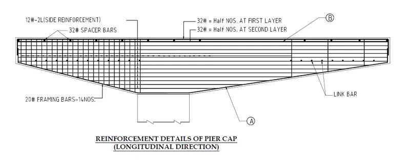
- The rest half of the reinforcement is provided below the other half by providing spacer bar in between them. This contribute as the main reinforcement and of which the rfcmnt needs to be embedded into the shaft.
- The 2nd layer of the reinforcement nomenclated as B has to cross beyond the pier to anchor properly.
- These are the main reinforcement of the structure.
- The provision for the drainage pipe should be provided and the reinforcement adjusted accordingly.
- the left part is less cantilever part of the structure. This part is being designed as a corbel.
- Designed as corbel where the loading span is less than the depth of the structure.
- Here the load flow is directly to the support at an angle of 45. So this is mainly designed as a shear resisiting structure.
- So need to design the corbel section for shear flexure , so we need to encase the horizontal links as shown.
- Vertical rebars provides safe load flow under direct compression.
- An outer ring is provided to convert the whole structure to bind in a single one.
- Some rebars is provided which is coming out from the shaft inot the pier. These need to be checked properly at the junction point to prevent form sliding/shear friction effect.
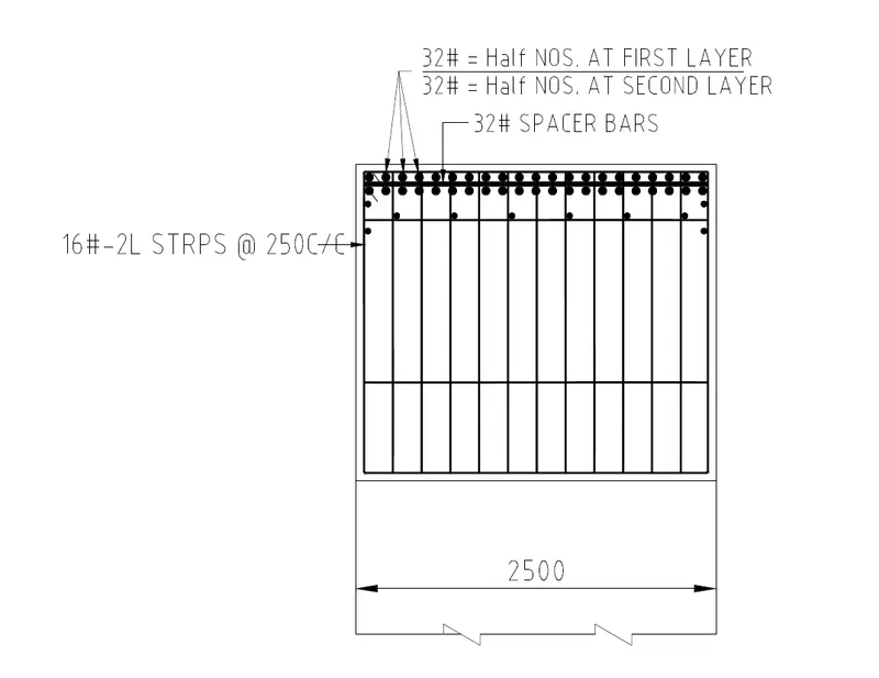
- SECTIONAL VIEW
- Here the main bars and the spacer bars can be visualize properly.
- The strirrups has been provided accordingly.
- the stirrups has be bend at an angle of 45 degree at the corner points to make proper joint at the location.