Challenge 5 : Concept Modeling of Car Bumper
1. Title of the Project : CONCEPTE MODELLING OF CAR BUMPER
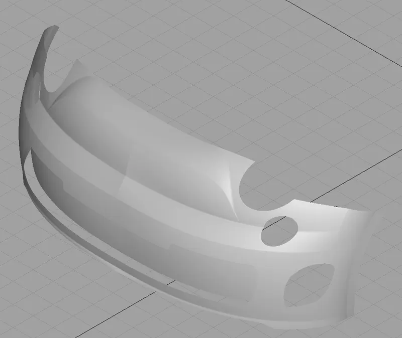
2. Objective : To build the bumper of the Abarth 500 car using ALIAS curves traced from the given blueprint of the car model.
Design methodology / approach :
A design approach for modelling this bumper Part has been briefly explained below using flow chart
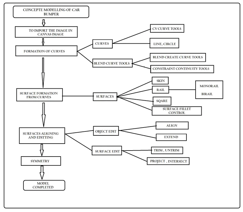
PROCEDURE:
Stage 1: To make a rectangular box with a dimension of 3657 X 1627 X 1485 as dimension of the car from the blueprint.
Stage 2: import the front and side view from the image. Use crop to crop out different views of the blueprint and by using image editor command decrease their visibility. Now scale and align all these images according to the box to fit all the views properly.
Stage 3 : Now according to the view start creating the curve networks to make a 3D image. These curve networks will be used to create the surfaces.
Stage 4: Now align all these curve according to a particular view and follow that view to make accurate 3D model.
Stage 5: Now with the help of curves and tools like skin, square and rail used to start making surfaces according to the image.
Stage 6: Now focus on the continuity, the flow of surface is one of the most important expect of the design so the flow should be even and continuous .check the flow using diagnostic shaders.
Stage 7: For the special are we have to use a speaical approach to follow to attain the destered surface, extend and intersect the surcafes isolate the surfaces to create it.
Stage 8: Intersect the suffaces then trim the surfaces to make the model more realistic as possible.
Final stage: Now focus on the detailing part like head lamps and back lamps to make it as realistic as possible. Also use surface fillet to make the joints smoother.
Features used
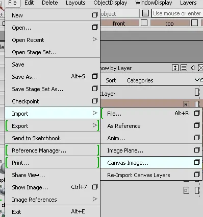
1. Import canvas images
Using import option we can insert 2D images as canvas images for modelling the Abarth 500 car bumper.
2. Marking menus
Marking menus had three forms picking tools, tranforming tools & information tools. It is more effective while modelling.
Picking tools
Using shift+ctrl+left mouse button we can use below picking tools.
- Pick object
- Pick cv
- Pick curves
- Pick surface
- Pick curve on surface
- Pick blend point
- Pick edit point
- Pick nothing
3.Transforming tools
Using shift+ctrl+middle mouse button we can use below transforming tools.
- Move
- Move pivot
- Scale
- Rotate
- Delete Locators
- Query edit histroy
4. Information tools
Using shift+ctrl+right mouse button we can use below Information tools.
- Information windows
- Toggle model
- Toggle grid
- Control on/off
- Plane editor
- Shade
5.Curves tools
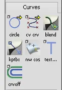
In curves, CV curves is important tool on alias. Here we used this tool for curve network of concept car. Also we used blend, circle, key point curve tools on required area to achieve entire curve network.
6.Surfaces tools
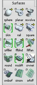
We learned how to create surfaces on curve network using Skin, Rail, Square and also Surface fillet.
Skin
If we have only two curve lines we can easily able to create surface using Skin surface tool. We can also use 3 curve line to create surface holding shift key and select curve.Also toggle to change the bend of surface by selecting the centerline curve and move the curve line.
Rail
To create surface using rail we need two curve line one as generation and other as rail curve. We can also use two lines as generation curve & 2 lines as rail curve to create surface.
Square
We can create surface, if we have 4 curve lines meeting each other. It create surface like patches.
Surface fillet
Surface fillet will create surface like L shape. We can create surface fillet by selecting srfillet and selecting two surface as primary and secondary surfaces.if we want to change use option like G2 curvature to form edge less surface as tertiary suraface.
7.Surface Edit
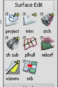
We learned how to use surface edit tools to get required shape of the surface.Using Project tool we can project a curve on surface and trim unwanted surface to get desired shape of surface.
We learned below tools on surface edit.
- Project
- Intersect
- Trim/Untrim
8.Interactive shading
Interactive shading use your system graphics to draw surface. There are two types: Hardware shade, Diagnostic shade.
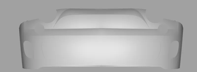
FRONT VIEW:
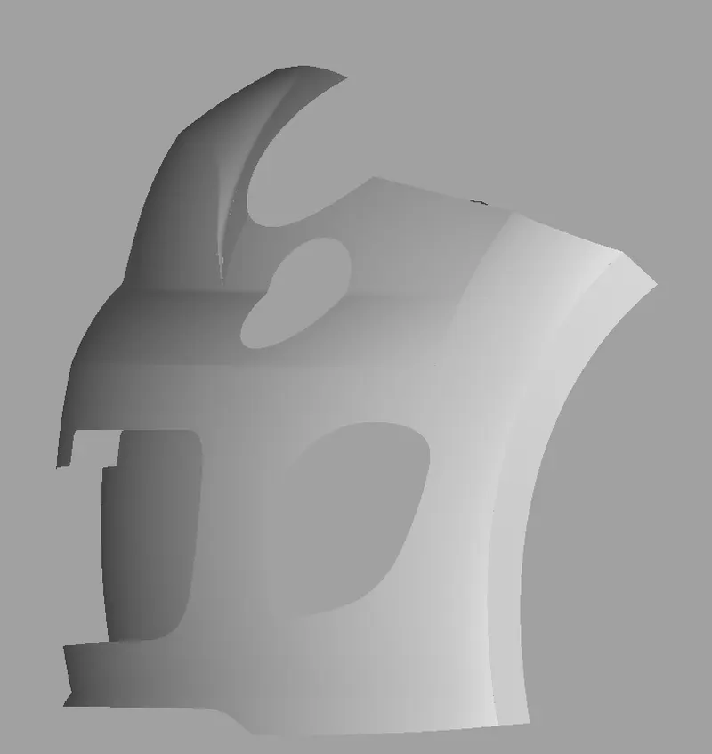
SIDE VIEW :
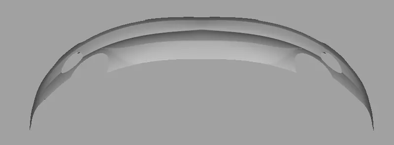
TOP VIEW :
ISOMETRIC VIEW:
Conclusion:
- We learned how to make surface on curve network using surface tools like skin, rail, square.
- We learned how to edit the surfaces using surface edit tools like project, intersect, trim, untrim.
- We learned how to acheive good quality surface using align tools or force surface to achieve good quality by manipulating degree & span.
- We learned how to visualise the model using diagnostic shade.
- We created surface model of concept car with good quality and continuity.