Challenge 4 : Concept Modelling of Alloy Wheel
TITLE OF THE PROJECT : CONCEPT MODELLING OF ALLOY WHEEL
1. Objective : To design the surface model of Alloy wheel using Autodesk alias.
2. Introduction : In the automotive industry, alloy wheels are made from an alloy of aluminium or magnesium. Alloys are mixtures of a metal and other elements. They generally provide greater strength over pure metals, which are usually much softer and more ductile. Alloys of aluminium or magnesium are typically lighter for the same strength, provide better heat conduction, and often produce improved cosmetic appearance over steel wheels. Although steels, the most common material used in wheel production, is an alloy of iron and carbon, the term "alloy wheel" is usually reserved for wheels made from nonferrous alloys.
3. Design methodology :
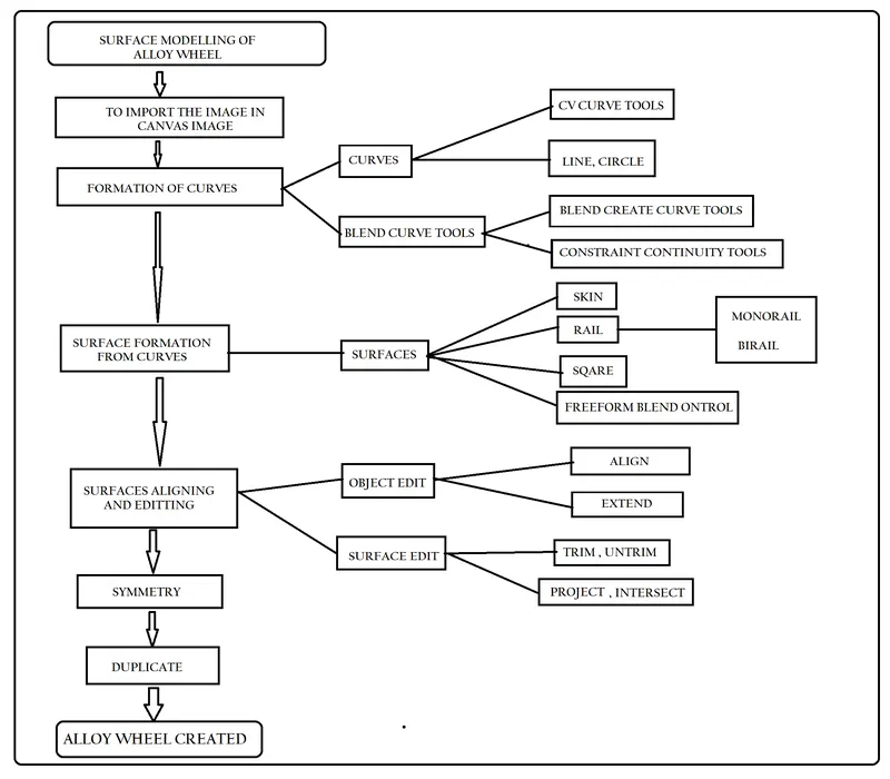
5. DESCRIPTION :
1. Skin:
The Skin tool to create a surface by connecting a set of profile curves.
the Surfaces tool palette, select the Skin Surfaces > Skin tool.
2. RAIL :
Creates a surface by sweeping one or more profile curves along one or two path curves or rails.
Surfaces tool palette, select the Swept Surfaces > Rail Surface tool .
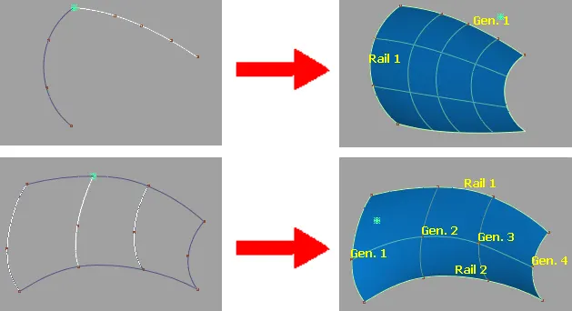
The Rail Surface tool takes its name from its use of one or two “rail” curves. The generation curves maintain contact with the rails.
The appearance of the Rail Surface icon depends on the Generation Curves and Rail Curves settings in the Rail Surface Options window.
- Monorail and Birail Control options
Generation Curves
1 – Sweep one generation curve along the rail curves.
2 – Blend between a start and end generation curve along the rail curves. Use the Gen. Blend Value slider to control the midpoint of the blend.
Continuity table :
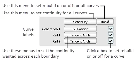
Continuity
G0 Position – Only keep positional continuity. This is the default.
G1 Tangent – Try to keep tangency with a surface that shares this edge.
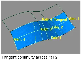
G2 Curvature – Try to keep curvature continuity with a surface that shares this edge.
3. Square :
Creates surfaces by blending four boundary curves , while maintaining continuity with adjacent surfaces.
Square Control
Continuity table
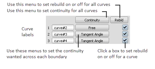
The Continuity Table displays one row for each boundary curve involved in the Square operation.
-
Use the pop-up menu next to each curve to set the level of continuity you want across that curve.
4. Project : The project tool is used to project the shapes on surfaces.
the Surfaces edit tool palette, select project > select surface > Go > select curves > project.
5. Trim :
Surfaces edit tool palette, select trim > select surface to trim > keep or discard.
Untrim :
Last – Undo the last trim operation on the surface.
All – Undo all trims on the surface.
6. Align :
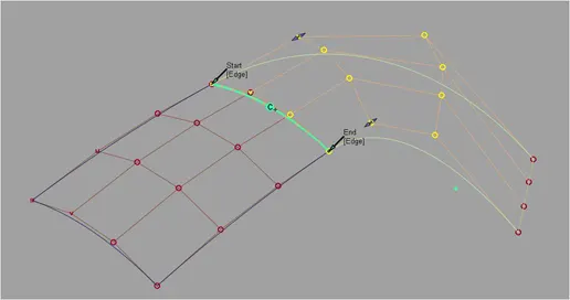
Aligns a curve or surface edge to another curve, or surface edge. Also aligns an edge to the interior of a surface.
Continuity
Continuity level between the aligned geometry: G0 Position, G1 Tangent, G2 Curvature, or G3 Curvature.
Lock Position Row
For G1, G2, and G3 continuity alignments, locks the position of the aligned edge CVs to prevent them from moving as you change options.
Alignment Type
Edge – This option is the default and provides alignments for all surfaces when a vector constraint is not used. This includes the alignment of a surface to a surface edge, isoparm, or curve-on-surface (CoS).
7. DUPLICATE OBJECTS :
The number of copies you want to create.
If you specify multiple copies, each copy is moved, rotated, and scaled relative to the previous copy.
Choose Copy to create real geometry.
Choose Instance to create a lightweight reference to the original. When the original is change, the instance is automatically updated.
Group Duplicate
Specifies whether the copied geometry should be a child of the same parent as the original geometry from which it was copied.
Copy Animation
Copy animation applied to the object. Checking on this option gives access to the Animation Parameters section (see below).
To duplicate an animated light, use Edit > Copy in the Multi-lister.
Auto Update
Automatically update the new object when the values in the Duplicate Object Control window change.
Return to Previous Tool
Turn this on if you want Alias to close the Duplicate Object following a duplication operation and return the focus to the tool you were previously using.
6.
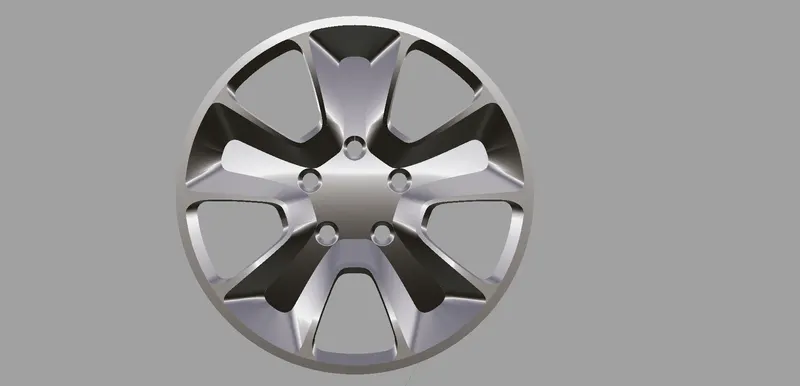
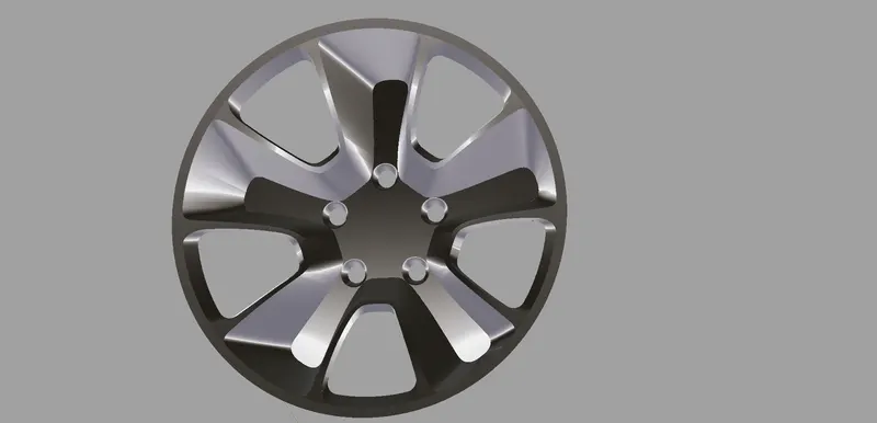
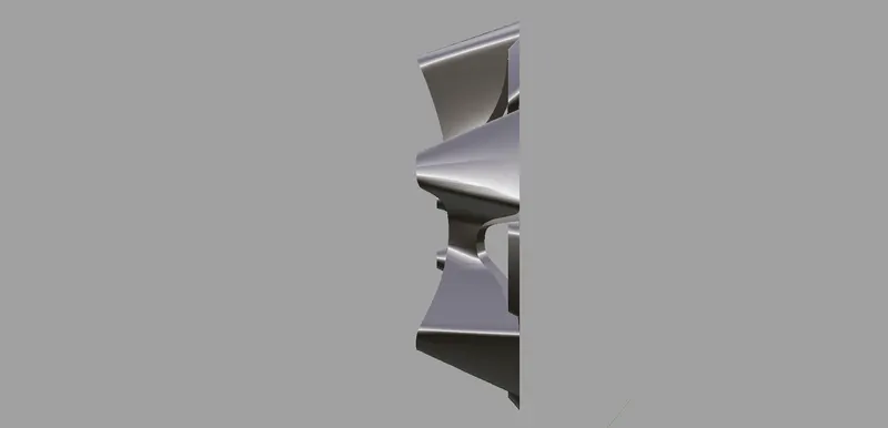
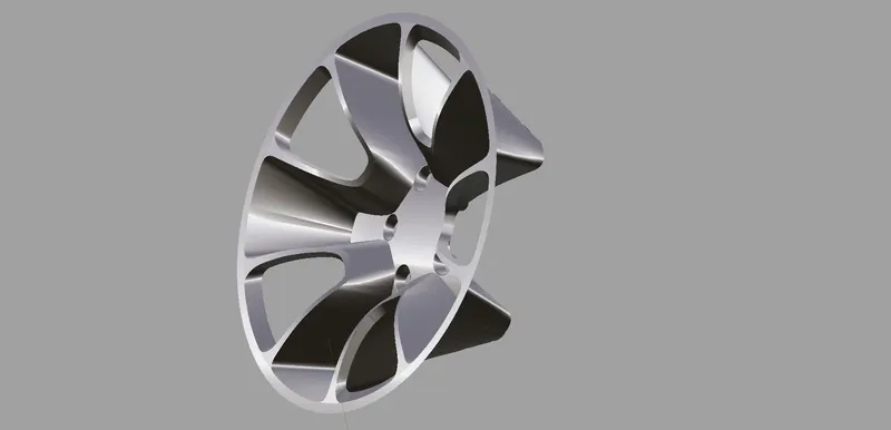
7. CONCLUSION : Finally using curves, object edit,symmetry, duplicate, surface and surface edit tools are used to produced the 3D model of alloy wheel.