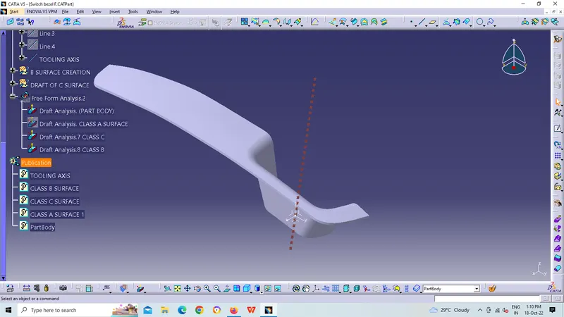
Week 8 - Challenge 2 - Switch Bezel Design
In order to obtain the proper draft analysis tooling axis is required and the following steps show how it is done.
As this component has 1 hole from where the tooling axis can be generated, however it does not have proper 4 walls to generate it. In this case, an approximation is made in order to obtain the tooling axis.
First by using the two side walls a dummy axis is made. As it is known that the draft angle is 3 degrees, the second axis is taken as a 3 degrees to the given wall and using these two axis the tooling axis is made.
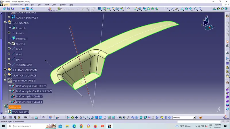
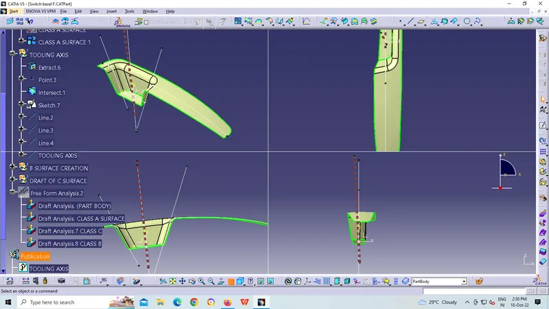
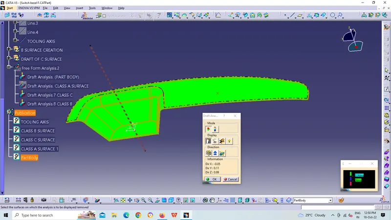
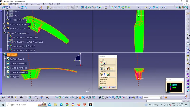
Screenshots of the Draft analysis of Class-A surface:
DRAFT ANALYSIS ON CLASS-A SURFACE:
- Go to insert> analysis> feature draft analysis
- Align the tooling axis with the compass.
- Click on the surface and see that the surface is within the permissible limit of the draft values.
- The surface should be green and in the column nominal value 3deg given as input. hence the draft analysis on the class-A surface is successfully performed.
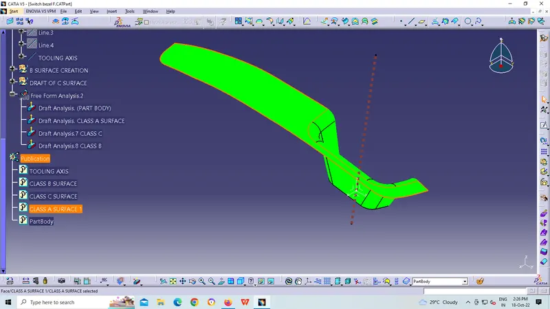
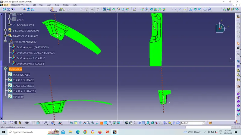
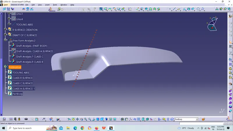
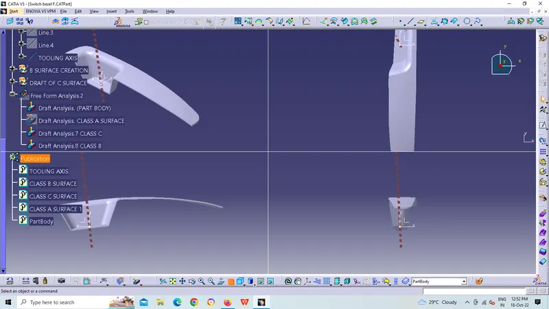
solid model with the proper color code of the draft angle in various orientations (Isometric, Front, Side, and Top View):