Challenge 5
Challenge 5
Prepare and analyse a transverse model of Deck slab with following specifications:
- Slab laid on top of 4 I-girders.
- Having supports spaced at 2.0m each.
- Having following geometrical properties:
Thickness of slab = 0.240m
Width of slab = 1.0m
4. Having material properties: Concrete, M55 grade.
AIM
Transition between a roadway pavement and bridge.Road level-level of road to which the level of bridge is adjoined by the approach slabBack wall-vertical wall at the end of the bridge supporting the expansion joints & extend up from abutment seat.Wing wall-adjacent to the abutments and act as retaining walls, provided at the both end to retain soil of earth filling for approach slab.Deck slab-a slab of concrete used to make the base for the roadway, railway, pedestrian walkaway, etc. on the bridge.
ANS- I am submitting the whole solution by screenshot whatever challenges is given in it .
STEP 1 BEAM CREARED BY NODES VALUE PUT
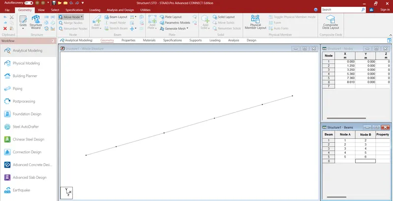
STEP 2 GO TO SUPPORT AND CREATE SUPPORT
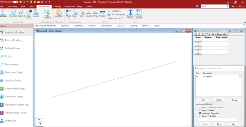
STEP 3 GO TO PROPERTIES AND CLICK ON DEFINE AND SET THE MATERIAL CONCRETE
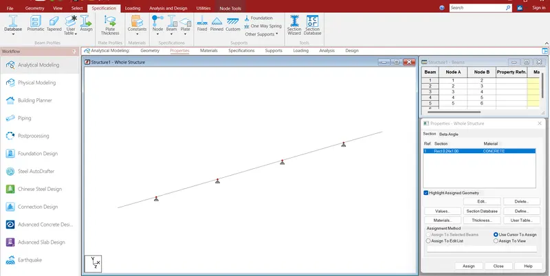
STEP 4 GO TO 3D MODULING AND CHEAK VIEW AND THICKNESS
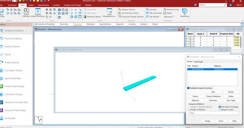
STEP 5 GO LOADING AND SET THE LOAD CASE DETAIL
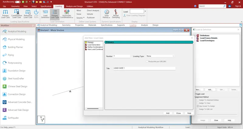
STEP 6 GO EDAGE LOAD SET THE VALUE OF DEAD LOAD
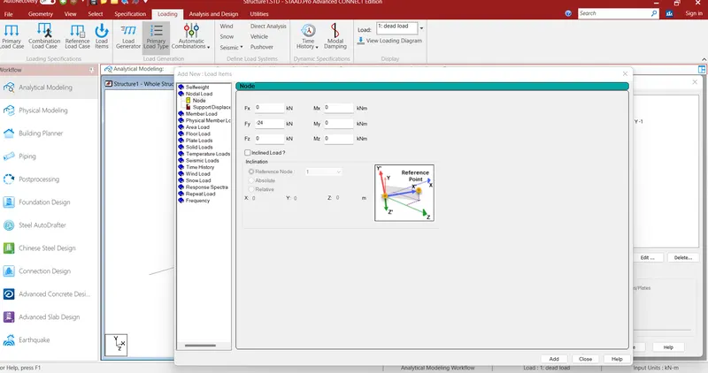
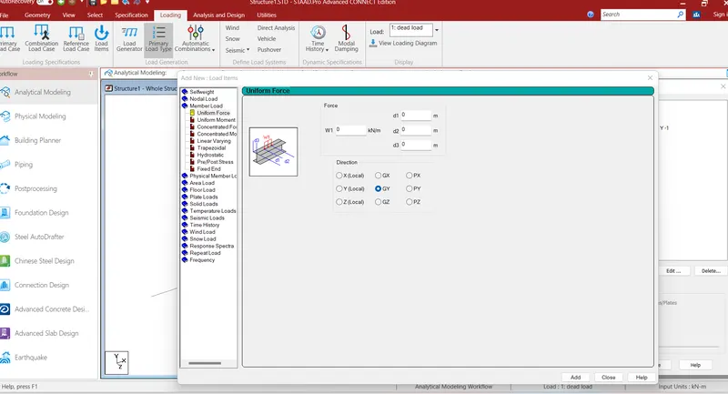
STEP 7 GO TO PLINTH LOAD AND CLICK ON MEMBER LOAD FOR SET THE UNIFORM FORCE
STEP 8 GO TO UTILITIES THEN CLICK ON NODE TOOLS THEN CLICK ON NODE DISTANCE
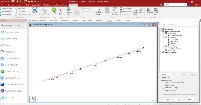
STEP 9 APPLIED THE UNIFROM LOAD OF THIS VIEW UNI GY -7 KN/M LOAD
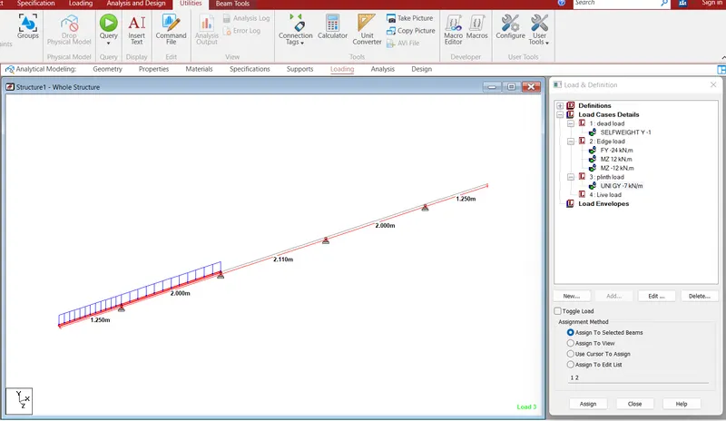
STEP 10 ALL LOAD APPLIED THEN SHOW THIS VIEW PLINTH LOAD SELFWEIGHT DEAD LOAD UNIFORM LOAD EDAGE LOADE
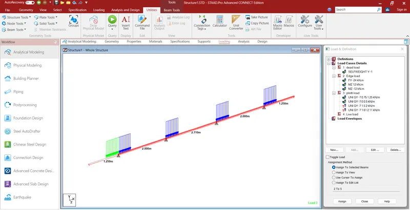
STEP 11 LIVE LOAD SHOW THIS BEAM APPLIED
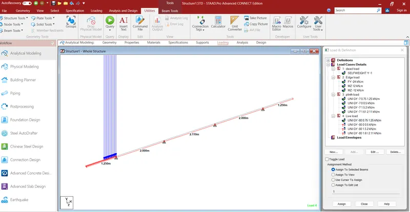
STEP 12 GO DEFINE COMBINATION FOR DESIGN SLAB
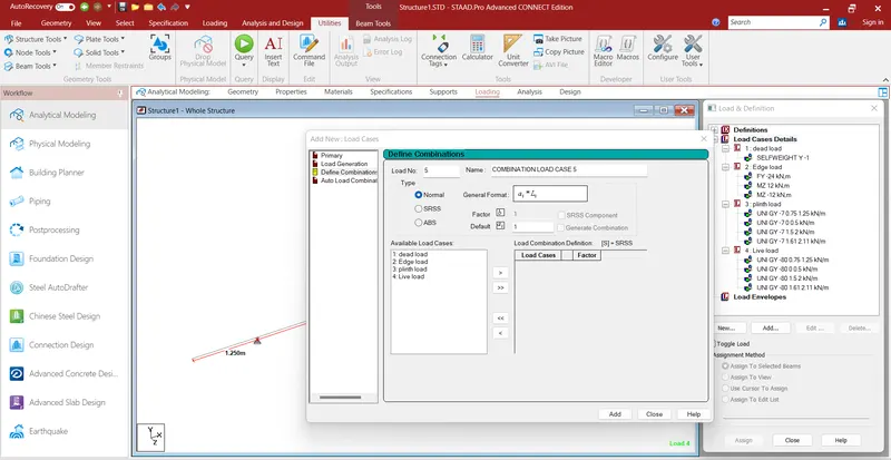
STEP 13 ALL LOAD COMBINATION IS SET
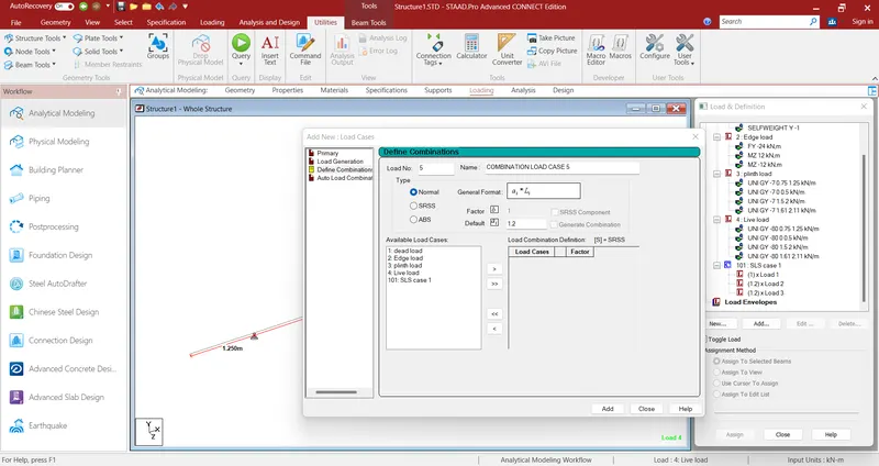
STEP 14 MOMENT LOAD APPLIED OF THIS VIEW MZ 12KN/M
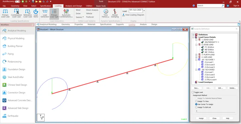
STEP 15 SLS CASE 1 APPLIED SHOW THIS VIEW
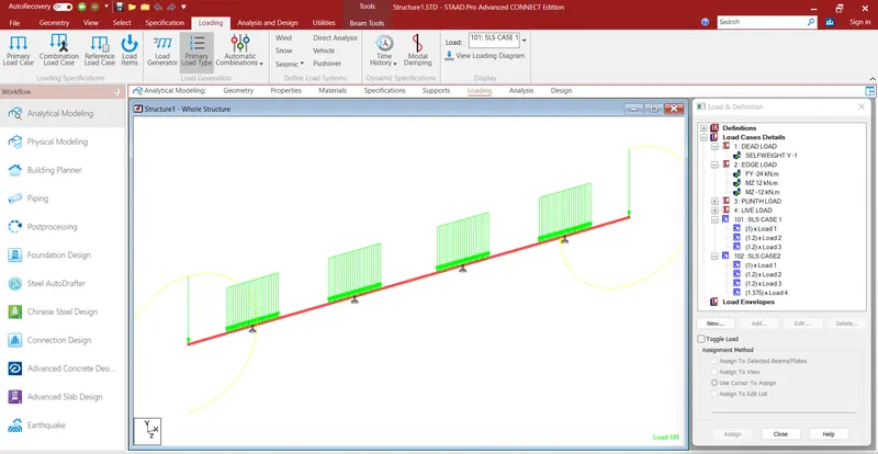
STEP 16 THIS VIEW IS APLLIED SELFWEIGHT OF BEAM
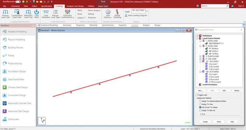
STEP 17 GO TO THE ANALYSIS DESIGN AND CLICK RUN ANALYSIS THEN GO TO POSTPROCESSING MODE OF THIS VIEW
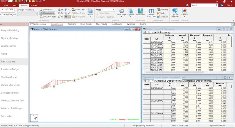
STEP 18 DEAD LOAD APPLIED VIEW
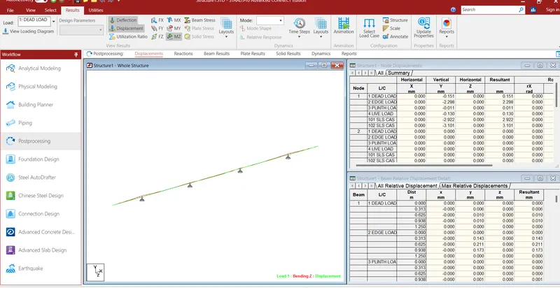
STEP 19 PLINTH LOAD APPLIED VIEW
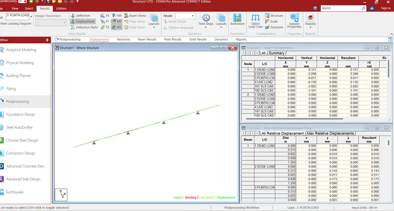
STEP 20 LIVE LOAD APPLIED VIEW
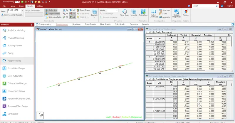
STEP 21 LIVE LOAD IN SLS CASE 1 COMBINATION OF THIS VIEW
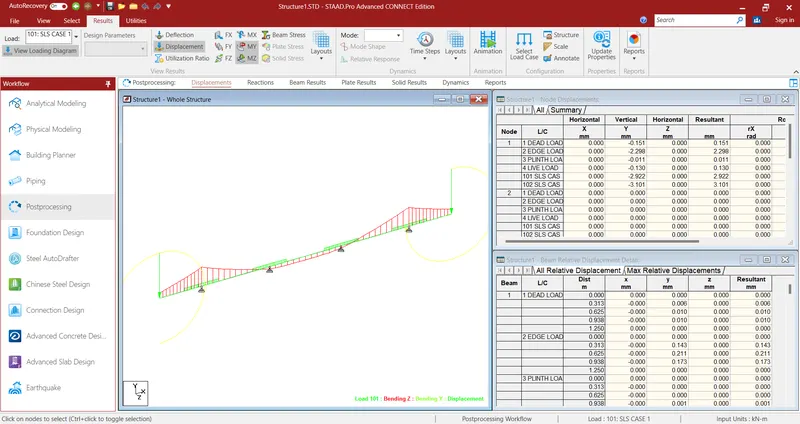
STEP 22 SLS CASE 2 LOAD COMBINATION 102 OF THIS VIEW
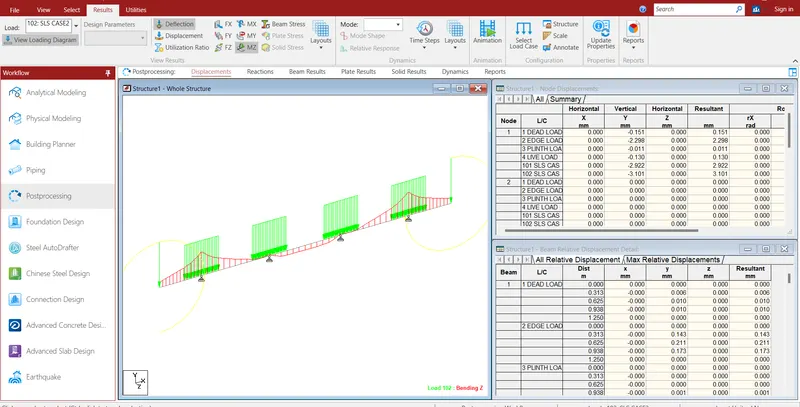
STEP 23 LOAD VIEW MAXIMUM AND MINIMUM
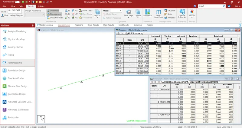
STEP 24 THIS IS I GIRDER PLATE
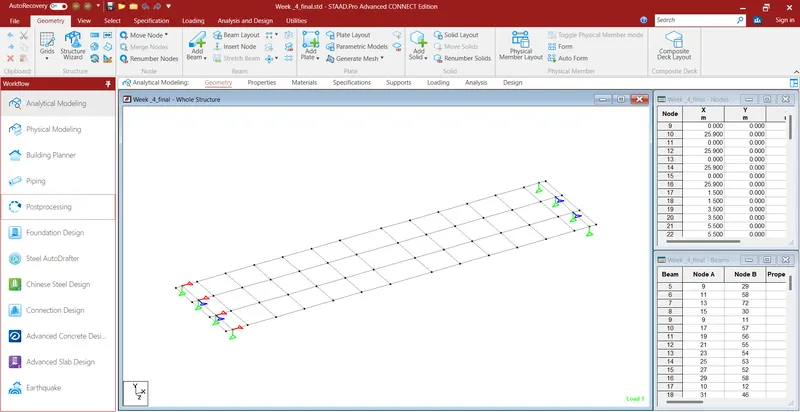
STEP 25 THIS I GIRDER BEAM LONGITUDIGNAL BEAM
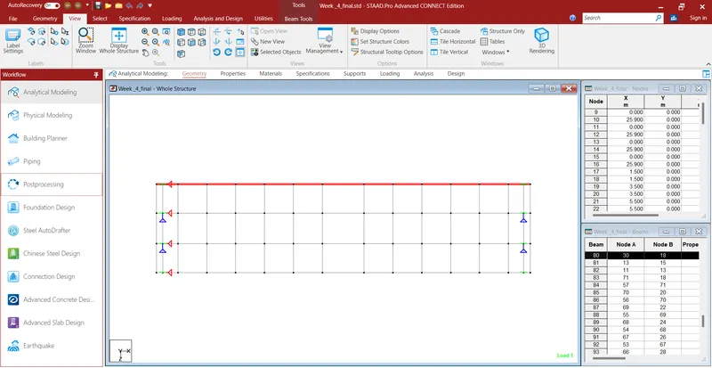
STEP 26 THIS TRAVERSE MEMBER OF I GIRDER
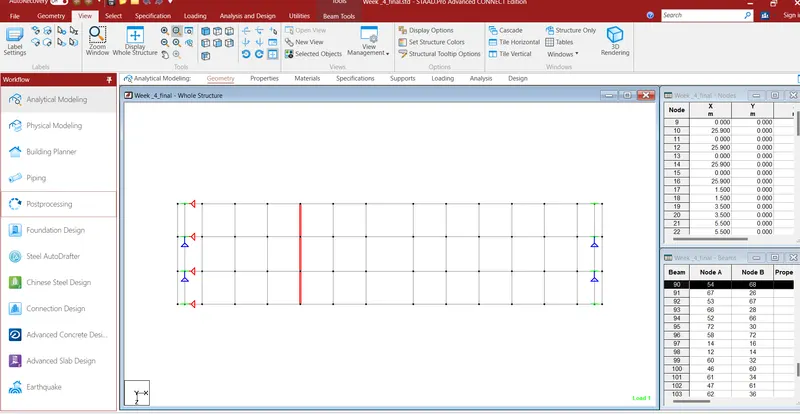
STEP 27 THIS END DIAPHARM VIEW I GIRDER
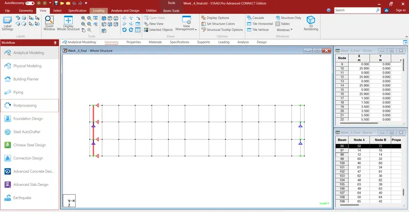
STEP 28 GO TO DIAPHARM SELECT AND CLICK ON NEW OF THIS VIEW
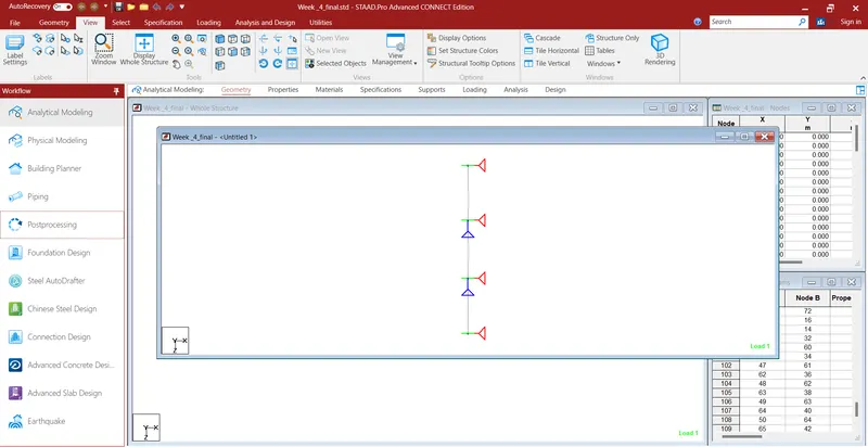
STEP 29 THIS BENDING DIAGRAM OF DIAPHARM
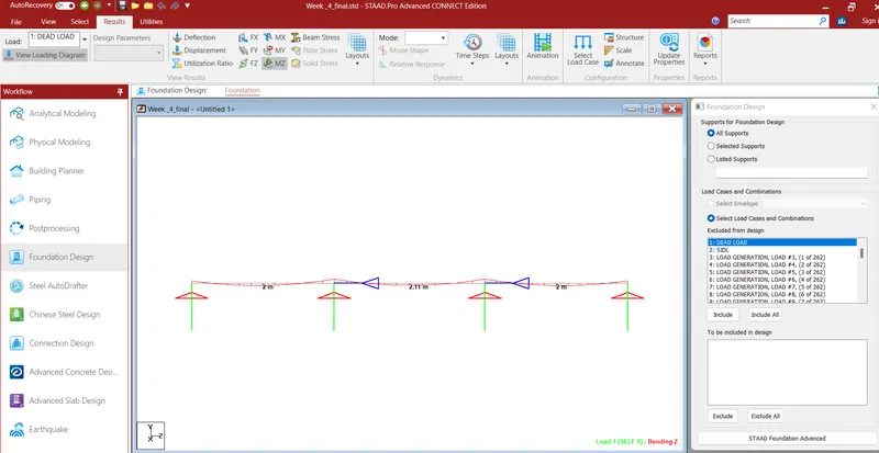
STEP 30 WHEN LOAD APPLIED SIDL OF THIS DIAGRAM
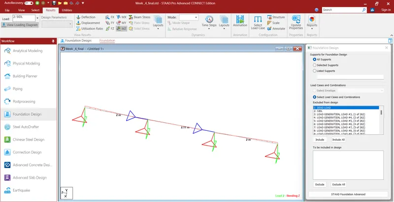
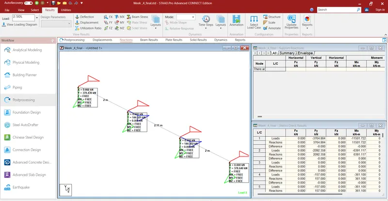
STEP 31 THIS BEAM REACTION VIEW OF DIAPHARM
I WRITE SOME OF M55 CONCRETE
Target strength = 60Mpa. Max size of aggregate used = 12.5 mm. Specific gravity of cement = 3.15. Specific gravity of fine aggregate (F.A) = 2.6.
OPC Cement 53 Grade – 330 Kg
GGBS – 200 Kg
Micro silica – 30 Kg
Water Cement ratio (w/c) – 0.25
Free Water – 140 liters
20mm Metal / Aggregates – 611 Kg
10mm Metal / Aggregates – 475 Kg
Crush Sand – 813 Kg
Admixture Dosage – 1.1 %
Admixture – 6.16 Kg
Density of Concrete – 2605 Kg/cum
The complete mix design file is attached herewith.
You can modify the mix design by changing the specific gravities of materials which will make it relevant as per the material available at your place.
Changing the specific gravity will change the weight of material in mix design which is automatically calculated.
Do not use this mixes directly without doing prior trials of it, the data provided is for educational and better understanding of mixes.
After doing trial, if any issue observed, you can do adjustment by adjusting the % of each size of aggregate to achieve the required properties of fresh concrete.
Do ensure total of all aggregate percentage in mix should some to 100%