Challenge 4 : Concept Modelling of Alloy Wheel
Topic:- Concept Modelling of Alloy Wheel
Objective:- To develop a conceptual design of the Alloy wheel from the given blue print
Introduction:- To create a alloy wheel using the Autodesk Alias AutoStudio 2021 software is used. Autodesk Alias is a family of Computer-aided industrial design software predominantly used in Automotive Design and Industrial Design for generating Class A surfaces using Bézier surface and NURBS modelling method. ALIAS uses NURBS surface and can be converted to Bezier's surface for more accuracy of continuity. In this exercise we use NURBS surface(we are not converting to NURBS surface) for the surface generation.
FlowChart:-
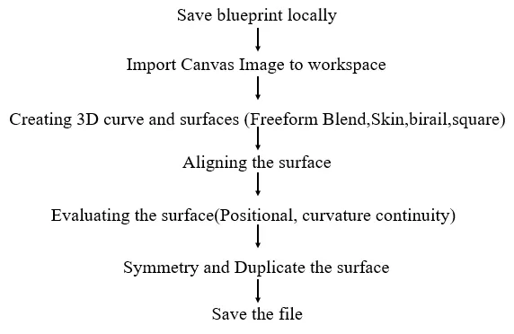
Description:-
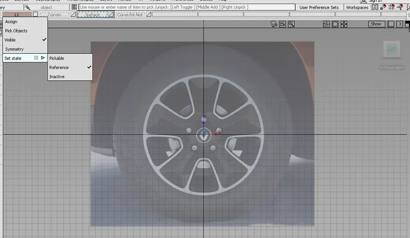
The given blueprint is laoded to ALIAS.
Adjusted to the required size by scaling up/scaling down.
The image is assigned to layer and set to Reference.
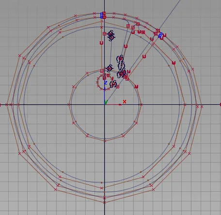
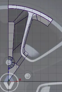
The required Curves and surfaces are generated as per the blue print.
I have used freeform blend,Skin,birail,square options to generate the surface.
We can see the image is symmetry and can be mirrored by using the axis.
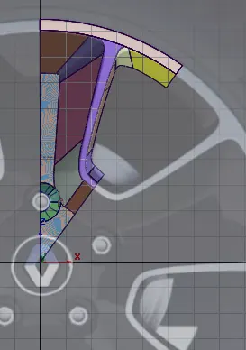
Steps in creating the surface:-
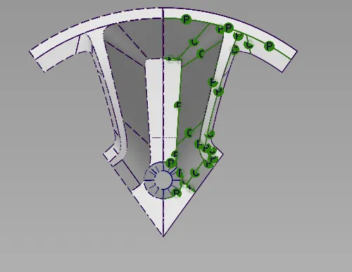
Traced the curve and ensured positional continuity(G0) is maintained.
The spans are maintained at 1 and ensured deviation is within 0.1mm

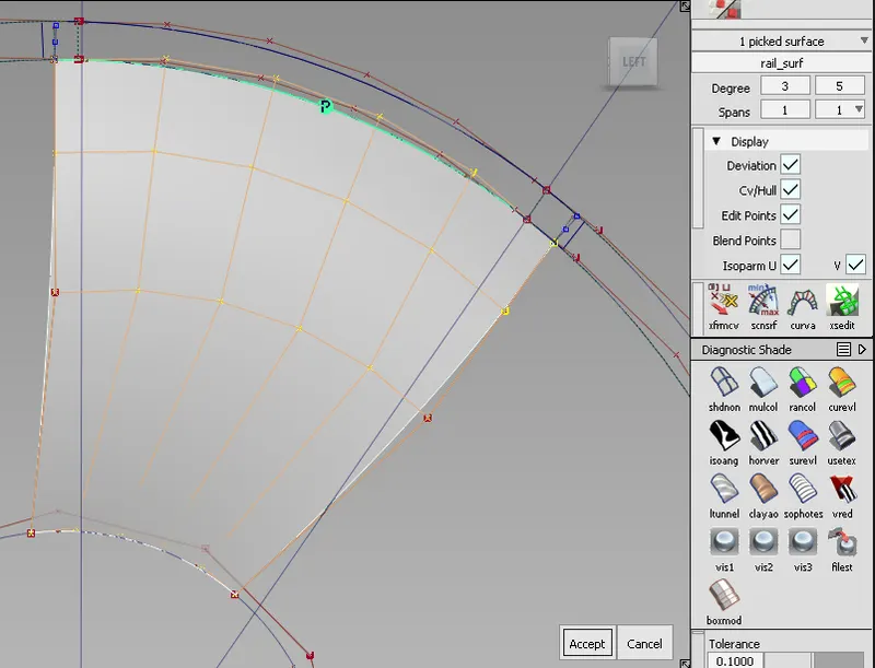
Pic depicting the Positional Continuity(G0) and the surface evaluation(G0).
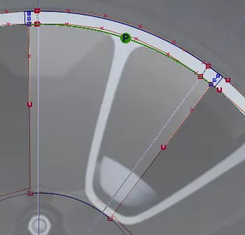
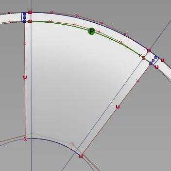
Blend:- Curves around the corner, blend is used and is ensured to maintain tangent continuity.
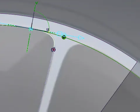
The profile curves are generated and are projected to the surface.
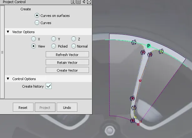
Curve projected to the surface
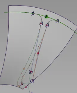
Trimmed Surface
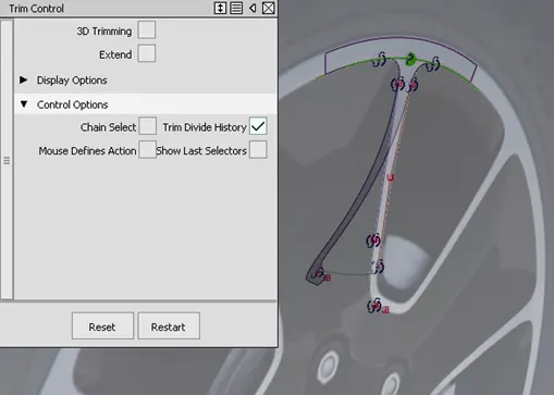
Generating the remaining surface
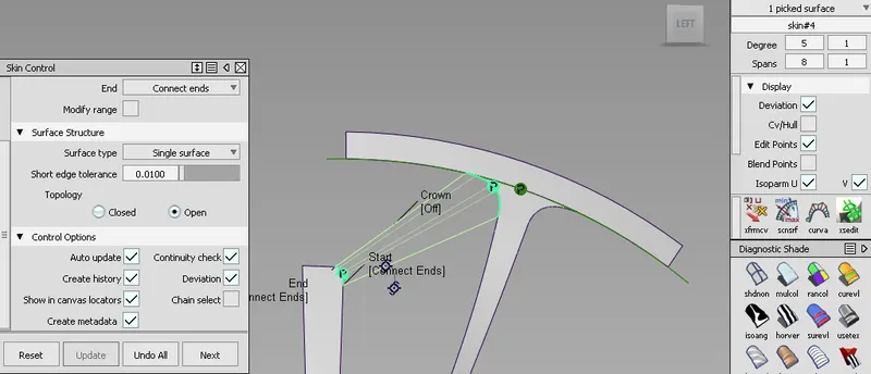
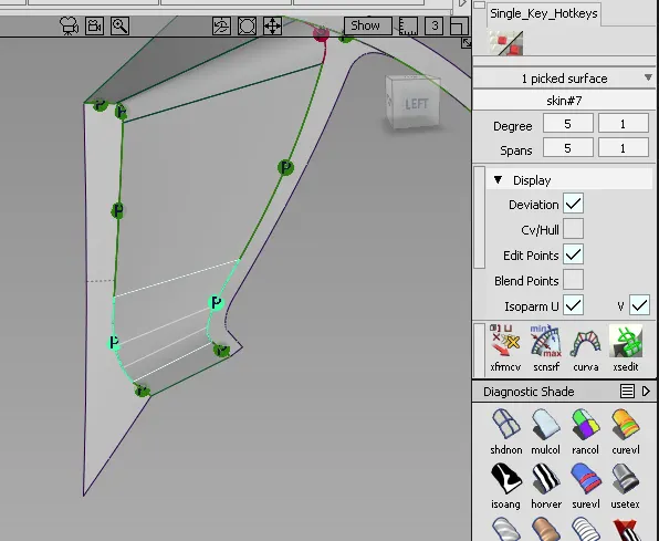
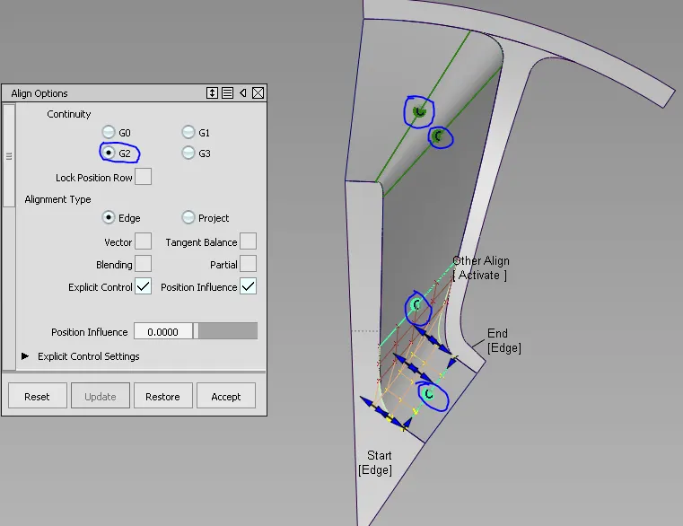
Aligning the Surface
We align the surface to make it curvature continuity
Below Highlighted indicates the surface that Curvature continuity has failed.
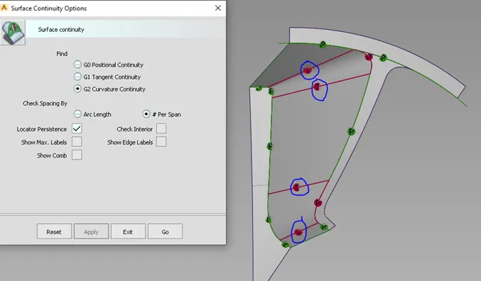
Surface aligning to maaet G2 Curvature Continuity
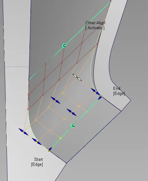
The surface are aligned and Curvature continuity are achieved.
Similarly the G0 posiional continuity is achieved. (2 trimmed surfaces)
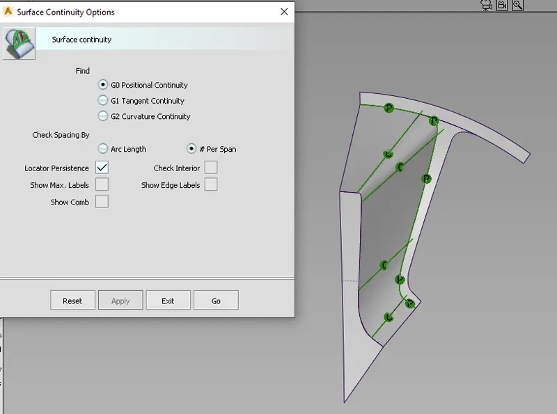
Image showing G0 Positional continuity & G2 Curvature Continuity
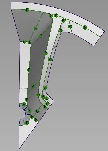
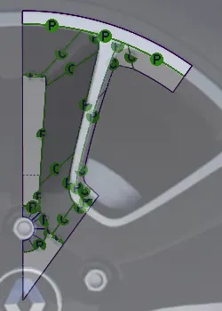
Symmetry Surface
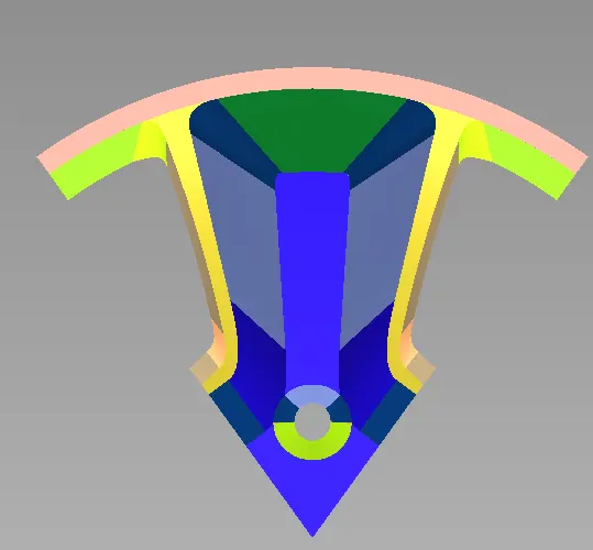
The surfaces are made symmetry
Different colors shows different surfaces generated
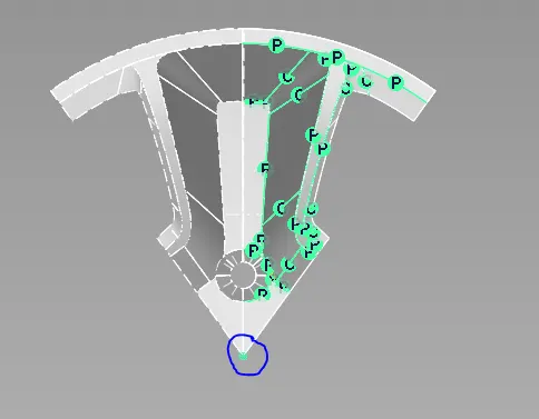
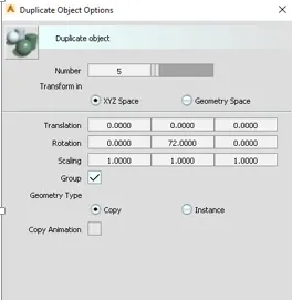
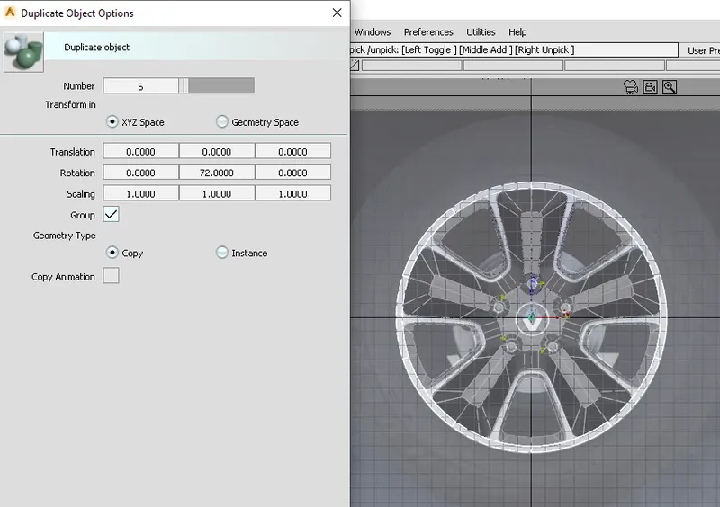
The Vertex are aligned to the tip of the profile to generate a rotated object.
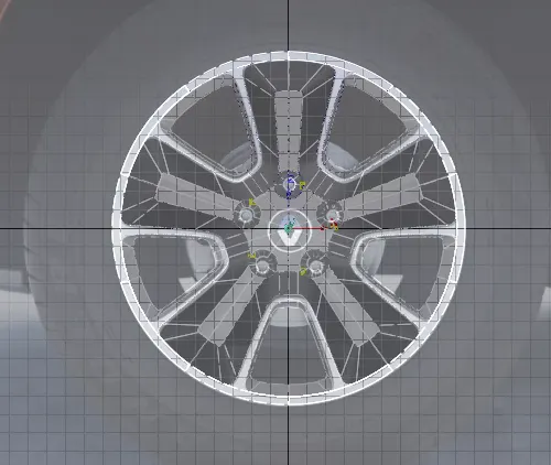
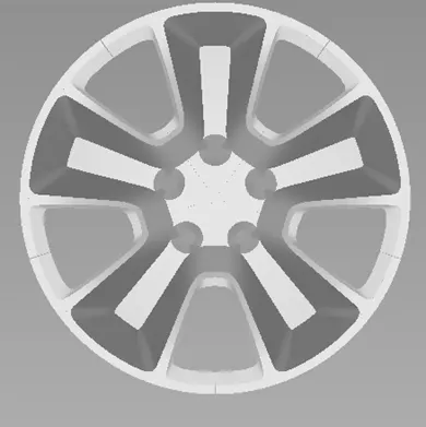
To rotate and create the Instances
The Surfaces are selected
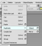
Edit - Duplicate - Object
Tools Used:-
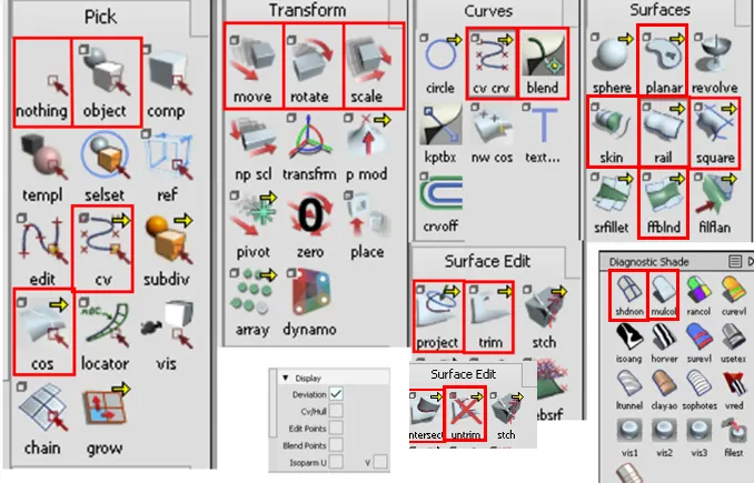
Pick
Nothing:- Used to deselect a partiular object
Object:- It is used to select a line,curve,surface
CV's:- It is used to select a CV curve
COS:-(Curve on surface) - It is used to select the curve generated on a surface either through Project
Transform
Move:- It is used to move a particular object in prescribed direction.
If we want the object in X-axis, then left mouse button is clicked(free form movement without any constaints in X-direction)
If we want the object in y-axis, then middlemouse button is clicked(free form movement without any constaints in Y-dirextion)
If we want the object in Z-axis, then right mouse button is clicked(free form movement without any constaints in Z-dirextion)
To snip the curve point to point, then Alt+left mouse button is selected.(it snips on the toggle grid)
To move the curve on another curve, then ctrl+alt+left mouse button is selected.
Rotate:- It is used to rotate a object in the prescribed direction.
If we want to rotate the object along X-axis(YZ plane), then left mouse button is selected
If we want to rotate the object along Y-axis(XZ plane), then middle mouse button is selected
If we want to rotate the object along Z-axis(XY plane), then right mouse button is selected
Scale:- It is used to scale down the image up and down.
Scaled up:- the image is selected and scrolled to the right.
Scaled sown:- the image is selected and scrolled to the left.
Curves
CV CRV:- It is used to generate a curve. The DoF can be increased to increase the number of vertex.
The more the DoF the more the vertex. The vertex is used to modify the curve.
Blend:- Is used to combine 2 curve into 1. The tangency of the curve can be adjusted by using the keypoint option.
Surface Edit
Project:- It is used to project a 3D curve to a 2D surface.
The surface is selected and the required curve is projected on to the surface of the curve.
Trim:- It is used to seperate a surface based on the required profile.
eg:- The projected surface can be used to trim the surface. The Selected surface of a side can be kept/discarded as needed.
Intersect:- To generate a curve between the 2 intersecting surface.
Untrim:- The profile of a trimmed surface can be undone to the previous existing profile using trimming.
Surface
Planar:- A surface can be generated from a closed circle or profile using this planar.
Skin:- 2 adjacent faces of a surface can be joined using Skin.
BiRail:- The generation curves and Rail curves needs to be selected for the serface edge of 2 surfaces. We have option to select 1,2,2_ generation curves and 1,2 rail curves.
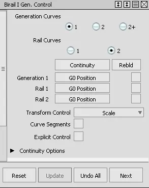
Square:- 4 bounded curves/surfaces are required to generate surface.
Freeform Blend Surface:- To create a curved surface between 2 surfaces and to maintain G2 curvature continuity this is used.
Front View:-
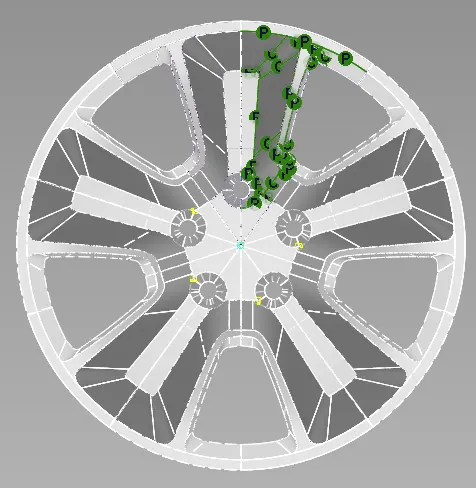
Side View:-
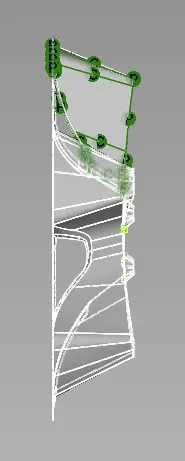
Top View:-
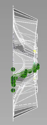
Rear View:-
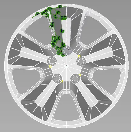
Final Model:-
Drive link:- https://drive.google.com/file/d/10HX4afQZjUwc6hF6R_2oc66H18c_ATpi/view?usp=sharing
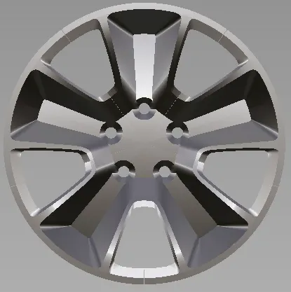
Conclusion:- The Concept modeliing of Alloy wheel using ALIAS is generated by tracing the curve.