Vehicle Dynamics - Ride Frequency, Roll And Pitch Analysis
xls link:-
https://drive.google.com/file/d/1GaTVRR0vQJOYGUiJknvQArjlUbP2MVt0/view?usp=sharing
Goal:
Select springs and anti-roll bars, and set up swing arm geometry(anti-characterstics) to meet targets for ride frequency, roll gradient and pitch gradient, while staying within certain constraints

Deliverables:
• Spring rates (front and rear)
• Roll bar diameters (front and rear)
• Rear ride frequency and flat ride plot (at 65 mph)
• Anti characteristics (front and rear - in terms of percentages and instant center locations)
• A small write-up on what you learn through this exercise
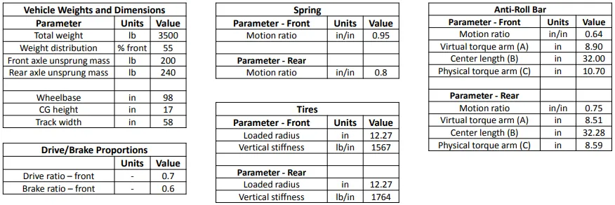
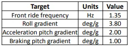

Targets:-
Front ride frequency - 1.35Hz
Roll gradient - 3.8deg/g
Acceleration pitch gradient - 2.00deg/g
Braking pitch gradient - 1.00deg/g
Constraints:-
Max. allowed front auxillary roll stiffness - 60%
Max. allowed rear auxillary roll stiffness - 30%
Process Map:-
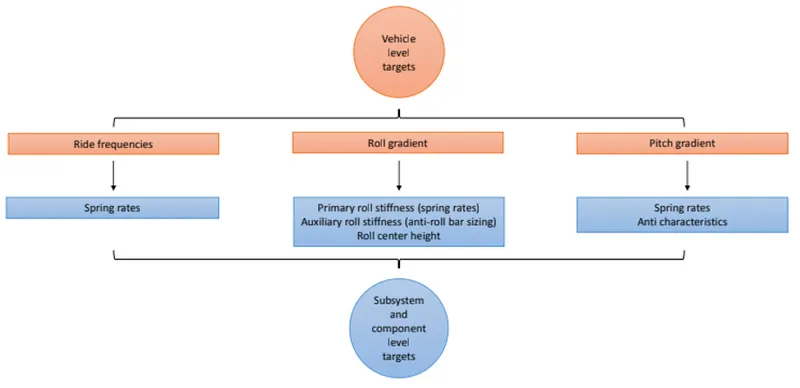
Solution:-
a) Ride Frequency:-
Ride Frequency is the undamped frequency generated in body during ride.
when the vehicle goes over a bump the front wheel comes in contact intitially followed by the rear wheel.
There is a time lag betweent the front and rear wheel hitting the bump.
This causes out-of-phase and pitching motion of the vehicle.
To prevent vehicle pitch the rear frequency has to be tuned to the front frequency to match the oscillations.
For a flat ride, rear ride frequency has to be greater than front ride frequency.
The wheel rate and spring rate can be calculated based on the ride frequency of front and rear.
More the frequency stiffer the ride(high frequency higher the spring rate, higher the spring rate higher the stiffness of the ride)
1) Time Delay(time_lag) due to Wheel base and speed(65mph)
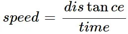
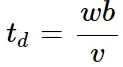
Where,
td - Time lag(sec)
wb - Wheel base(m)
v - velocity(m/s)
Frequency is given by,
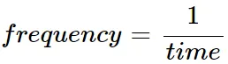
Front time period(s) is,
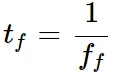
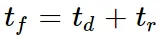
Rear time period(s) is,
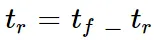
Rear frequency(Hz) is,
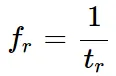
ff is Front frequency in Hz
fr is Rear frequency in Hz
tf is time front
tr is Time rear in Sec
Front frequency - 1.35Hz
Rear Frequency - 1.48Hz
Rear frequency has to be higher than front frequency for flat road condition.
Rear frequency = 1.0962X Front frequency
2) Calculating Front ride rate and rear ride rate
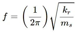
The ride rate is given by,
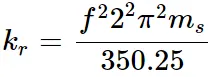
350.25 is to convert m/s to lb/in
f- ride frequency in Hz(based on (1), front and rear frequency)
ms- sprung mass in lb
kr - ride rate in lb/in
Wheel rate is the measure of effective stiffness of the suspension system at wheel center.
wheel rate is given by(lb/in),
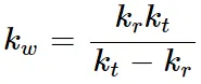
kt - vertical stiffness of the tire (or) Tire rate in lb/in
Spring rate is the amount of weight required to compress a spring by 1 inch

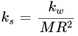
MR = Motion Ratio(in/in)
ks-spring rate
kw-wheel rate
3) Frequency Data Analysis and Tuning the Rear Ride frequency
The function to represent the oscillation profile os given by,
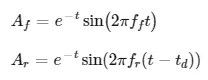
Af - front amplitude
Ar - Rear amplitude
t- time instance
td - time delay
The 5% of front frequency is added to the rear frequency, to study and plot the damping characterstics.
Listed below Rear frequency are considered and analysed using the function.
1) rear frequency calculated (from 1)
2) rear frequency = 5% X front frequency = 1.4175Hz
3) rear frequency = 10% X front frequency = 1.4883Hz
4) rear frequency = 15% X front frequency = 1.5627Hz
The difference in front and rear amplitude are plotted.
The difference in amplitude(front and rear) signifies the % error that rear frequency has to be compensated or tuned to coincide with the front frequency.
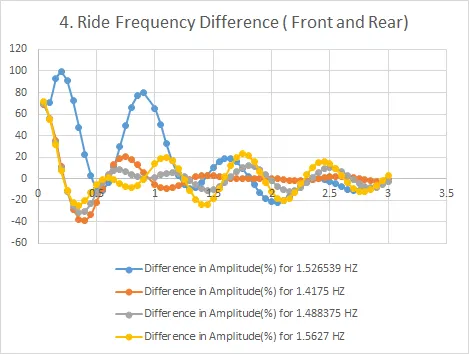
The data analysis and observations from the above chart are as follows,
1) Rear Frequency corresponding to 1.52Hz (Blue curve) - The variation in error is maximum and the oscillations reaches minimum after 2sec.(Curve analysis shows flat ride will be after 2sec)
2) Rear Frequency corresponding to 1.4175Hz (Orange curve) - The variation in error is minimum and the oscillations attains minimum peak within 1sec(Curve analysis shows flat ride will be attained within 1sec).
3) Rear Frequency corresponding to 1.488Hz (Grey curve) - The variation in error is minimum and the oscillations reaches minimum peak within 1sec(Curve analysis shows flat ride will be attained within 1sec).
4) Rear Frequency corresponding to 1.5627Hz (yellow curve) - The variation in error is maximum and the oscillations doesn't reach minimum even after 3sec.
If rear frequency is tuned to 1.4175Hz and 1.488Hz will provide the best output for the flat ride condition and the corresponding wheel rate and tire rate can be determined.
MATLAB program to plot Bump profile
clear all
close all
clc

% Inputs
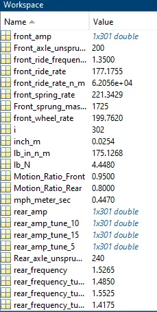
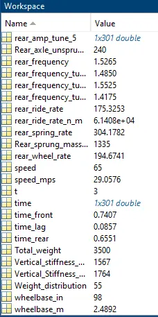
Total_weight = 3500             % weight in lb
Weight_distribution = 55        % % front
Front_axle_unsprung_mass = 200  % weight in lb
Rear_axle_unsprung_mass = 240   % weight in lb
Motion_Ratio_Front = 0.95       % unit in in/in
Motion_Ratio_Rear = 0.8         % unit in in/in
Vertical_stiffness_Front = 1567 % unit in in/in
Vertical_Stiffness_Rear = 1764  % unit in lb/in
front_ride_frequency = 1.35     % unit in HZ
wheelbase_in = 98               % unit in in
speed = 65                      % unit in mph

% unit conversion
lb_N = 4.448;                    % lb to N
inch_m = 0.0254;                 % in to m
lb_in_n_m = 175.1268;            % lb/in to N/m
mph_meter_sec = 0.44704;         % miles per hour to meter per second

% 1) Rear Frequency
wheelbase_m = wheelbase_in * inch_m;    % unit in m
speed_mps = speed * mph_meter_sec;

%frequency_front = 1/time;
time_front = 1/front_ride_frequency;

% speed = distance/time
time_lag = wheelbase_m/speed_mps;

% time_front = time_lag + time_rear
% time_rear = time_front - time_lag
time_rear = time_front - time_lag;

rear_frequency = 1/time_rear;

% 2) Front and rear wheel and spring rate
Front_sprung_mass_weight = (Total_weight*Weight_distribution/100) - Front_axle_unsprung_mass;
Rear_sprung_mass_weight = (Total_weight*(100-Weight_distribution)/100) - Rear_axle_unsprung_mass;


front_ride_rate_n_m = 4*(pi^2)*(front_ride_frequency^2)* (Front_sprung_mass_weight/2);  % unit in N/m
front_ride_rate = front_ride_rate_n_m/(lb_in_n_m + lb_in_n_m);

rear_ride_rate_n_m = 4*(pi^2)*(rear_frequency^2)* (Rear_sprung_mass_weight/2);  % unit in N/m
rear_ride_rate = rear_ride_rate_n_m/(lb_in_n_m + lb_in_n_m);

front_wheel_rate = (Vertical_stiffness_Front * front_ride_rate)/(Vertical_stiffness_Front - front_ride_rate);   % unit in lb/in
rear_wheel_rate = (Vertical_Stiffness_Rear * rear_ride_rate)/(Vertical_Stiffness_Rear - rear_ride_rate);        % unit in lb/in

% wheel_rate = spring_rate * motion_ratio^2
front_spring_rate = front_wheel_rate/Motion_Ratio_Front^2;  % unit in lb/in
rear_spring_rate = rear_wheel_rate/Motion_Ratio_Rear^2;     % unit in lb/in


% Bump oscillations
% Actual calculation
% Tuning parameter
% rear frequency = Front frequency + 5%
rear_frequency_tuning_parameter_5_percent = front_ride_frequency * 1.05
rear_frequency_tuning_parameter_10_percent = front_ride_frequency * 1.1
rear_frequency_tuning_parameter_15_percent = front_ride_frequency * 1.15


time = 0:0.01:3;
i=1;
for t=0:0.01:3;
    front_amp(i) = exp(-t)*sin(2*pi*front_ride_frequency*t);
    rear_amp(i) = exp(-t)*sin(2*pi*rear_frequency*(t-time_lag));
    rear_amp_tune_5(i) = exp(-t)*sin(2*pi*rear_frequency_tuning_parameter_5_percent*(t-time_lag));
    rear_amp_tune_10(i) = exp(-t)*sin(2*pi*rear_frequency_tuning_parameter_10_percent*(t-time_lag));
    rear_amp_tune_15(i) = exp(-t)*sin(2*pi*rear_frequency_tuning_parameter_15_percent*(t-time_lag));
    i=i+1;
end

figure(1)
plot(time,front_amp);
hold on
plot(time,rear_amp);
grid on
title('Bump oscillation - Actual Calculated(1.5265Hz)');
xlabel('Time(sec)');
ylabel('Amplitude');
legend('Front','Rear');

figure(2)
plot(time,front_amp);
hold on
plot(time,rear_amp_tune_5);
grid on
title('Bump oscillation - 5% Rear Tuning(1.4175Hz)');
xlabel('Time(sec)');
ylabel('Amplitude');
legend('Front','Rear');

figure(3)
plot(time,front_amp);
hold on
plot(time,rear_amp_tune_10);
grid on
title('Bump oscillation - 10% Rear Tuning(1.488Hz)');
xlabel('Time(sec)');
ylabel('Amplitude');
legend('Front','Rear');

figure(4)
plot(time,front_amp);
hold on
plot(time,rear_amp_tune_15);
grid on
title('Bump oscillation - 10% Rear Tuning(1.562Hz)');
xlabel('Time(sec)');
ylabel('Amplitude');
legend('Front','Rear');
Outputs:-
Bump oscilaltion curve for Front and Rear frequency
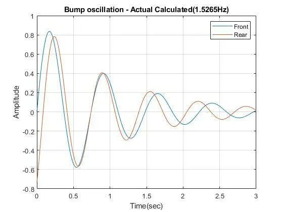
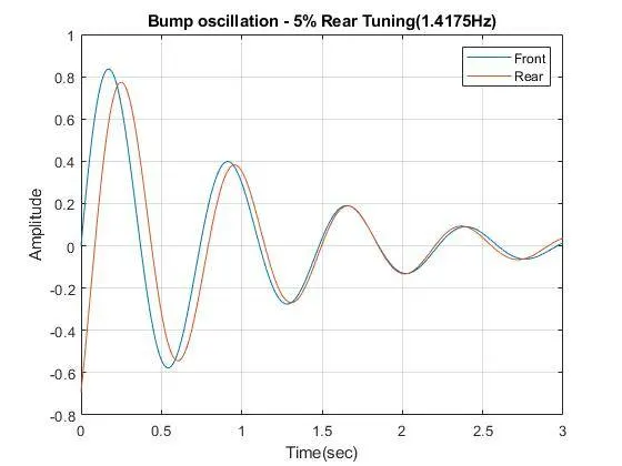
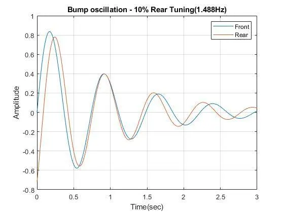
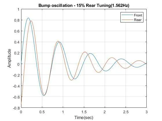
From the above Bump oscillation curve, we can determine that at rear frequency 1.4175Hz a flat ride can be achieved within 1sec.
(from the xls sheet(X xolumn), we can see the max amplitude error between front and rear frequency is at 0.54sec and after 0.75sec the error % drops gradually and after 0.95sec the error percentange is less than 10%)
The Ride rate,wheel rate and spring rate corresponding to rear frequency(1.4175Hz) is determined.
b) Roll Analysis:-
The Roll gradient target is given and roll stiffness contribution due to Anti-roll bar is determined and has to be within the given limits.
The primary roll stiffness is determined by the spring rate. If the roll stiffness is out of limits then the rear frequency has to be tuned to attain the roll stiffness limits.
when the vehicle takes a corner, the lateral load transfer takes place due to lateral acceleration.
Total Roll Moment due to sprung mass
Roll moment is a moment that tends to cause a vehicle to roll along longitudinal axis(Y-axis)

M_phi - Total roll moment - (ft-lb/g)
M_phi(lateral) - Lateral Component - (ft-lb/g)
M_phi(Gravity) - Gravity Component - (ft-lb/g)
Lateral Component:-
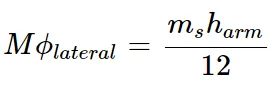
ms - Sprung mass - unit in lb
harm - roll moment arm (or) height of roll moment arm
12 - conversion factor from inch to feet
To find h_arm
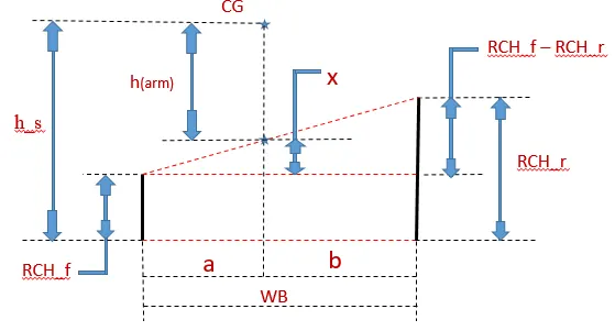


By similar triangle rule
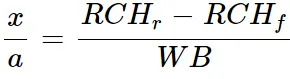

Gravity Component:-
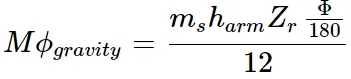
ms - sprung mass - (lb)
Z_r - roll gardient - (Deg/g)
Lateral load transfer has 3 components
* Lateral load transfer due to unsprung mass
* Lateral load transfer due to direct load/Sprung mass
* Lateral load transfer due to body roll
The total lateral load tranfer is given by:-

Lateral load transfer due to unsprung mass
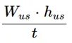
W_us = mass due to unsprung mass (lb)
h_us = CG height due to unsprung mass (in)
t = track width (in)
Lateral load transfer due to direct load/Sprung mass
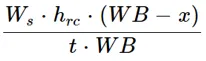
W_s =mass due to unsprung mass (lb)
h_rc = height of the roll center due to sprung mass (in)
WB - Wheel base (in)
Lateral load transfer due to body roll
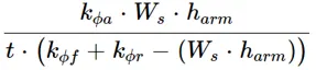
k_(phi.a) - Roll stiffness of the axle (front and rear) (lb/in)
h_arm - roll moment arm (in)
The total lateral transfer is a component of Vehicle weight, track width, CG height.
therefore, we subtract load transfer due to sprung mass and unsprung mass to obtain the lateral load transfer due to body roll.

TLLT - Total lateral load Transfer
(from the above, the total lateral load transfer due to roll(elastic) for front and rear can be determined).
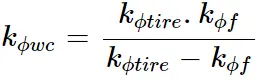
The roll stiffness is a contribution of springs, tire and Anti-roll bar. The contribution by springs are call ed primary stiffness and the contribution by anti-roll bar is secondary stiffness.
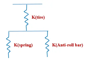
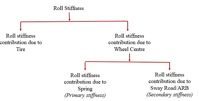
The roll Stiffness at wheel Cneter level is given by

where,
k_wc = stiffness due to wheel center
k_s = stiffness due to springs
k_arb = stiffness due to ARB
The tire and ARB are in parallel, so the general eqn is given by
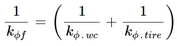
k_(phi.f) = Front roll stiffness
where, roll stiffness of wheel center
Roll stiffness of the spring(primary) is given by
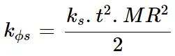
if the constarints are within the limits, then the anti-roll bar can be designed.
If the roll stiffness is not within the limits then Spring rate has to be updated and carry out the ride frequency bump oscillation analysis to satisfy the parameters.
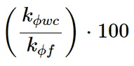
Auxillary Roll stiffness can be found by using,

The roll stiffness has to be checked for front and rear by,
Design of the Anti-Roll bar
The Dia of the anti roll bar can be found using the below equation

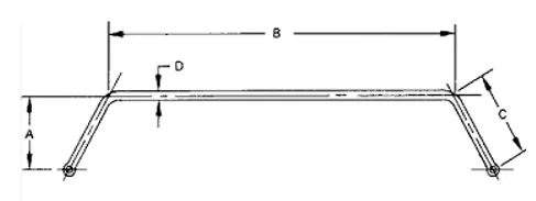
OD = Outer Diameter (in)
A = Virtual Torque arm (in)
B = Central Length (in)
C = Physical Torque Arm (in)
t = Track width (in)
MR = Motion Ratio (in/in)
C) Pitch Analysis
Pitch is the weight transfer from front to rear or weight transfer from rear to front during acceleration or Braking.
The pitch parametrs are determined for Braking and acceleration.
Longitudinal Load transfer
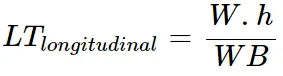
W - Total weight (lb)
h - CH height (in)
WB - Wheel base (in)
Deflection under load
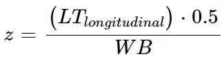
Where,
K_w = Wheel rate (lb/in)
Pitch Angle (deg)
It is the angle in which the vehicle is going to deflect horizontally along longitudinal direction.
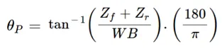
Z_f = Deflection under load (front) - (in)
Z_r = Deflection under load (rear) - (in)
4) Swing arm geometry
It is the horizontaql and vertical distance from contact patch to the Instantaneous center
Front IC vertical distance from contact patch - 9.5 (in)
Front IC horizontal distance from contact patch - 72 (in)
Rear IC vertical distance from contact patch - 8.5 (in)
Rear IC horizontal distance from contact patch - 90 (in)
values are obtained by the iteration of the Acceleration pitch gradient and Braking pitch gradient.
5) Pitch Analysis for Anti-lift and Anti-Squat(acceleration)
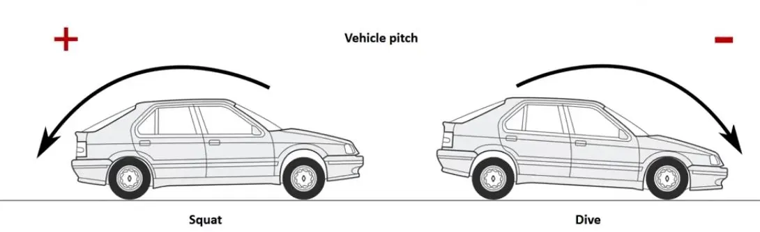
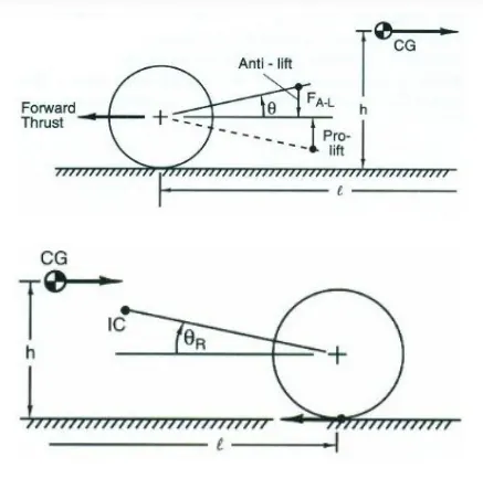
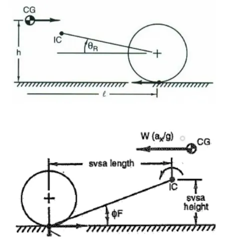
Anti-Lift:- It is the reduction of rebound effect in front suspension and reduction of Jounce in the rear suspension when acceleration.
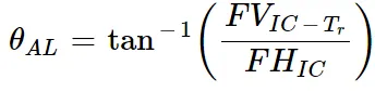
Anti-lift Front,
Anti-Squat:-It is the reduction of jounce effect in front suspension and reduction of rebound in the rear suspension when Braking.
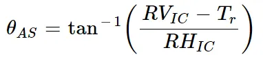
Anti-Squat Rear,
Swing arm is given by,
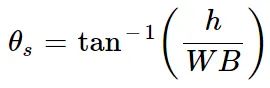
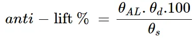
Anti-lift % is given by,
Anti-Squat % is given by

Front end deflection with compensation
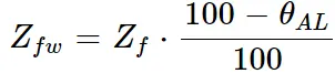
Rear end deflection with compensation,
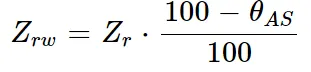
% Compensation,
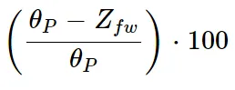
Acceleration pitch gradient,
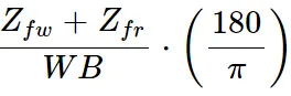
Where,
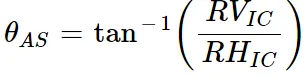
theta_AL = Anti-lift angle (deg)
theta_AS = Anti-squat andle (deg)
theta_d = drive ratio
Theta_s = Swing arm angle (deg)
theta_P = Pitch angle (deg)
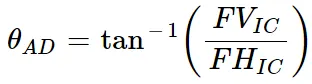
FV_IC = Front IC vertical distance from contact patch (in)
FH_IC = Front IC horizontal distance from contact patch (in)
RV_IC = Rear IC vertical distance from contact patch (in)
RH_IC = Rear IC horizontal distance from contact patch(in)
T_r = Tire Radius (in)
h = CH Height(in)
Z_fw = Front end deflection with compensation
Z_rw = Rear end deflection with compensation
6) Pitch Analysis for Anti-Dive and Anti-Squat(Braking)
Front Anti-dive angle is given by,
Rear Anti-squat is given by,
The Anti-dive % is given by,

The Anti-squat % is given by,

Results:-
Srings
a) Front - 221.5 lb/in
b) Rear - 304.25 lb/in
Anti-roll Bar Diameter:-
a) Front - 1.0167 in (or) 25.82mm
b) Rear - 0.5652 in (or) 14.35mm
Auxillary Roll Stiffness:-
a) Front - 53.911 ft-lb/g
b) Rear - 13.03 ft-lb/g
Pitch Gradient:-
a) Acceleration- 2.00 deg/g
b) braking - 1.00 deg/g
- Nalin PrabhathThis is really informative. Thanks for sharing.