Challenge 3
1. What are the sectional properties we need upfront for designing a metro viaduct? What is the supporting software for identifying the sectional properties and designing them?
Ans:
- Following are the sectional properties we need to upfront for designing a metro viaduct:
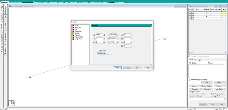
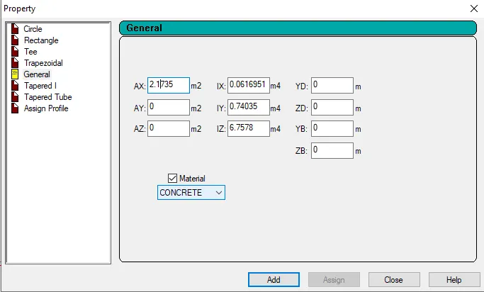
- Area of section: 2.1735015659 m^2
- Perimeter of section: 15.8758651 m
- Bounding Box: X:-2467.8857 -2582.1143
- Y: -593.7628 -1276.2372
- Centroid of section: X: 0.000, Y: 0.000
- Moment of Inertia: X: 7.403E+ 1 1 , Y: 6.7578E+ 11
- All these values are from AutoCAD and STAAD PRO will identify this values and it helps us to design the structure.
2. Explain the detailed steps involved how elements are created in STAAD Pro and how are the inputs for sectional properties assigned?
Ans:
- To assign the sectional property, first of all the model need to be created.
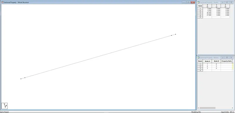
- The first node at 0,0 & 0 created.
- The nodes corresponding to the span length of 27m is created.
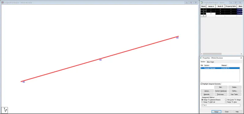
- The beam connecting the nodes is to be created
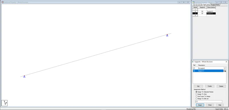
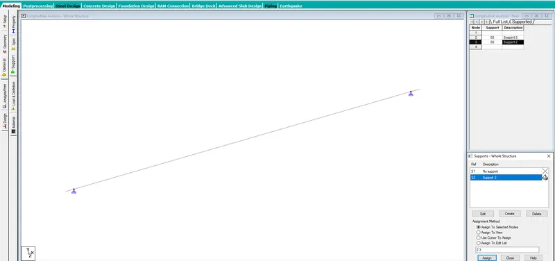
- Then pinned support created and assigned to the concerned nodes.
- The sectional property as defined has been created .
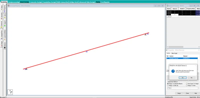
- The sectional property as defined has been assigned to the created model.
3. What are SLS combinations used for live loads, with respect to impact factor and how the moments for the section are derived?
Ans:
The SLS Combination for Live Load (Moment M)= Dead load+ 1.2*SIDL+1.1*Live Load*I
where,
Impact (I)= 1+(0.15+8/6+L)
4. What is prestressing in girders? What are advantages of Prestressed girders in a metro project.
Ans:
- Prestressing is a concept in which the compressive stresses introduced at bottom of girder and those compressive stresses counter balance the tensile stresses that will generate by all type of loadings. Basically this is concept in which compressive stresses is being introduced by tendons at tension zones.
- Advantages of Prestressed Girders in a metro project:
- The use of the prestressed technique in concrete gives it greater strength, by providing an internal compression force which counteracts the traction force produced by the loads of the structural elements.
- One of the great benefits of the prestressed girders is the elimination of cracks from all of the load stages. This absence of cracking supposes the structure’s greater capacity to withstand loads, impacts, vibration and knocks, while minimising the possibility of corrosion in the steel, thus increasing the durability of the construction.
- The prestressed girders saves the cost of construction and gives lighter weight material.
5.Explain about prestressing losses? What are different type of prestressing losses and mention the significance of the prestressing losses?
Ans:
The force which is used to stretch the wire to the required length must be available all the time as prestressing force if the steel is to be prevented from contracting. Contraction of steel wire occurs due to several causes, affecting reduction in the prestress. This reduction in the prestressing force is called loss in prestress. In a prestressed concrete beam, the loss is due to the following:
- Elastic shortening
- Shrinkage of concrete
- Creep of concrete
- Frictional loss
- Relaxation of steel
- Anchorage take-up
| S.No. | Types of Losses | Pre-Tensioning | Post-Tensioning |
| 1 | Elastic deformation of concrete | Yes | No loss due to elastic deformation if all the wires are simultaneously tensioned. If the wires are successively tensioned, there will be loss of prestress due to elastic deformation of concrete. |
| 2 | Relaxation of stress in steel | Yes | Yes |
| 3 | Shrinkage of concrete | Yes | Yes |
| 4 | Creep of concrete | Yes | Yes |
| 5 | Friction | No | Yes |
| 6 | Anchorage grip | No | Yes |
Friction
- In the case of pre-tensioning, there is no loss due to friction as the concrete is not being hardened at the time of tensioning the tendons.
- In the case of post-tensioning, the tendons are provided inside the duct of a precast concrete member. So the loss in prestress occurs due to friction between the concrete surface and the tendon in the process of tensioning. The loss of friction is also accompanied by the wobble effect.
Elastic shortening of concrete
- In the case of pre-tensioning as we cut the tendons the concrete shortens within a short interval of time by a certain amount which causes loosening of steel tendons. Hence causing a loss in prestress.
- In the case of post-tensioning as the concrete is already hardened, after cutting the tendons the concrete doesn't shorten further. But if the tendons are provided one by one instead of providing simultaneously, the provision of the second tendon causes loosening of the1st tendon, the provision of 3rd tendon causes loosening of 1st and 2nd tendon and so on. So, if the tendons are provided simultaneously the loss due to elastic shortening is zero in the case of post-tensioning. But if the tendons are provided sequentially, the provision of a tendon causes loss of prestress in earlier provided tendons.
Anchorage slip
- Anchorage, as the name signifies, is a component that is used to anchor the tendons into the concrete while terminating the tendons. The main function of anchorage is to transfer the stressing force to the concrete once the stressing process is completed.
- In the case of pre-tensioning, the tendons are monolithically embedded into the concrete. So, no external anchorage is provided and hence there is no loss due to anchorage slip.
- In case of the post-tensioning system as the tendons are provided inside the ducts of a precast concrete member. So anchorage is provided at either end of the tendon to transfer the stressing force to the concrete. If the anchorage displaces from its original position (generally the wedge slips immediately before attaining the proper final position) it allows loosening of the tendons thereby causing loss of prestress.
- Deformation due to rearrangement of molecules over a period of time under the application of a constant load is called creep. The deformation of concrete along the direction of tendons, makes them loosened thereby causing loss in prestress.
Shrinkage of concrete
- The volumetric changes of concrete structures due to the loss of moisture by evaporation is known as concrete shrinkage or shrinkage of concrete. Due to shrinkage of concrete, the tendons are loosened and loss in prestress occurs.
Relaxation of steel
- Relaxation of steel is defined as the decrease in stress with time under constant strain. Due to the relaxation of steel, the prestress in the tendon is reduced with time. Just like creep, relaxation also depends on time. It depends on the type of steel, initial amount of prestress, and the temperature.
6. How a girder is being prestressed while fabrication? Explain the components/materials used during the prestressing?
Ans:
- While fabrication the highly tensile steel or wires are inserted in the beam from one end to future beam.
- These prestressed tendons are inserted for prestressing of the girder. The steel strands are stretched to create an extremely high state of tension or stress and anchored in bulkhead at the end of the beam.
- The long prestressing and fabricating bed allows more than one beam to be made at the same time for economy and efficiency the steel strands are pulled and tensioned through two beams at once.
- After all the steel is in place the metal forms are positioned on both sides of the steel cages for the concrete mix. The metal forms will create the traditional I-beam shape of the finished prestressed concrete beam and concrete is poured into the tops of the forms.When the forms are removed the finished concrete beam emerges displaying its iconic I-beam shape.
- It is now “prestressed pretensioned” because the concrete has formed and hardened around the tensioned steel strands.Hence the girder is ready to take to the site and used in construction.
7.How are stresses in the girder calculated with the resultant prestressing losses?
Ans:
- Prestressing Force Applied (P)=(0.765fpu x As x n x (1-Loss)/1000 kn
- Where,Nominal Area of strand: (As)Nominal Ultimate Stress: (fpu)Maximum Jacking stress: 0.765 fpuModulus of elasticity: (Ep)We take No.of strands: (n)
For Section Modulus (Z)= I/y
For Stress at Bottom= P/A + P*e/Z - M/Z
8. Explain the step wise procedure of transverse analysis of open web structure of U girders in STAAD pro along with how the vehicle parameters and loadings are fed in the STAAD software.
Ans:
- For transverse analysis whole structure has to be modelled & designed as per FEM. So we will first create coordinates for U girder. having slab width of 4m and height of web is 1.8m.
- Node creation for the model is started from 0,0 & 0 points.
- Nodes for a single section of the U-girder is being created.
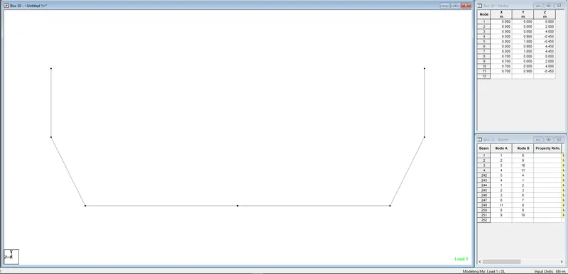
- The section is to be continued till the whole length of the span.
- The first translation will be at the support section which is at 0.7m from both the ends.
- The total length of the span is 30.2m.
- The c/c distance of the supports is 28.8m
- The next sections is made by translational repeat with 1.6m spacing upto the last segment of required length.
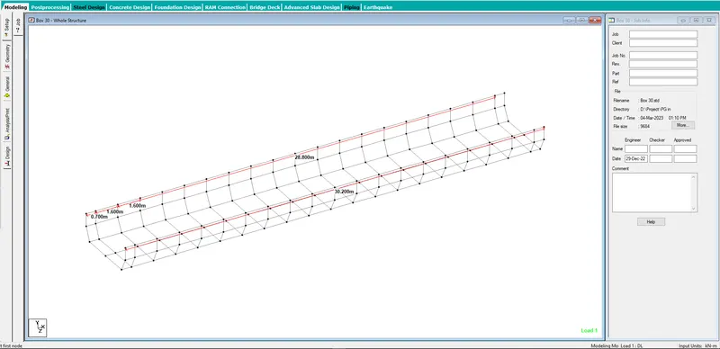
- Plates to be created for the created model.
- Then the plates to be created for whole the span.
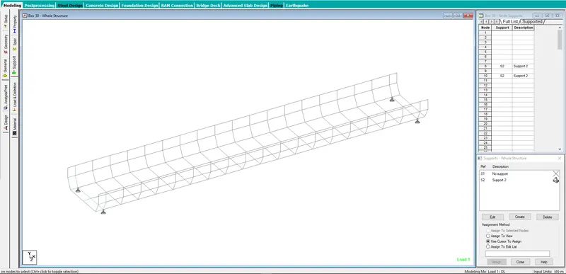
- Then the supports needs to be assigned.
- Go to general -> Support->Create ->Pinned -> Add -> Close -> Assign to the related nodes.
- Then the thickness/property for the plates/beams need to be defined.
- For base slab
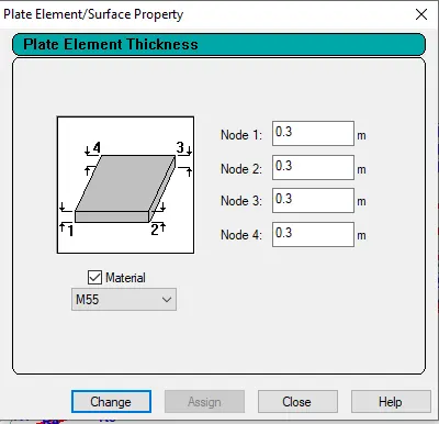
- For Straight web
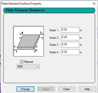
- For inclined web left
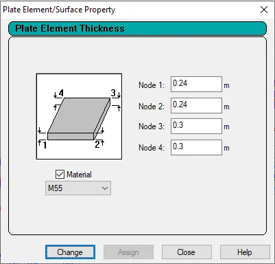
- For inclined web Right
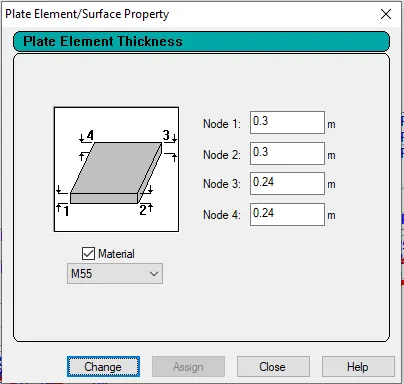
- Dummy member for the beams also created.
- 3D view of the model.
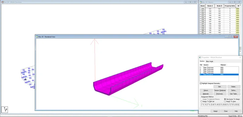
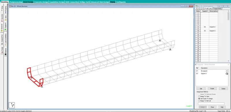
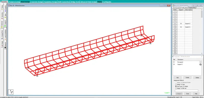
Loads & Definations
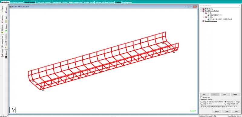
- Dead load will be added as self weight with factor Y-1.
- SIDL is applied as follows, it includes all the track, rail pad, plates attached etc loading. Each plate is 1.6m in length X coordinates is given as -0.8 to 0.8m and since width is 1m Y coordinate is given as -0.5 to 0.5m.
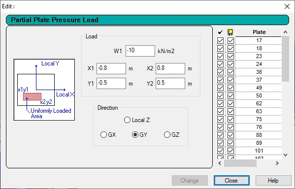
- Then the defined load case is to be applied to the concerned plates.
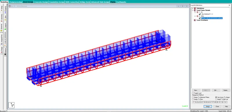
- Boggie loading- The maximum loading will occure when the train arrangement is in center. As the center distance of the chain arrangment is 4.4 so the wheel load will be at 2.2 m distance on either side.
- So it will occure at a distance of 0.6m after 1 plate from the center. CG in x dir is 0.8m. So 0.2m is the X co-ordinate and in Y direction the co-ordinate is 1-1.51/2 = 0.245 m.
- The loading is applied at four locations as a node point loading according to the corresponding plate.
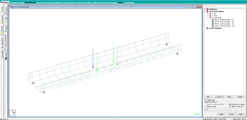
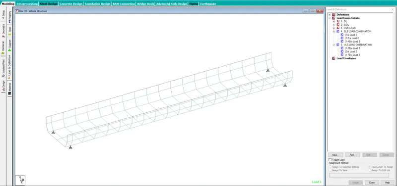
- Then the load combinations for ULS and SLS is to be applied.
- The SLS load combinations is applied with the combination by calculating the impact factor as described in the IRS code.
Analysis and Results
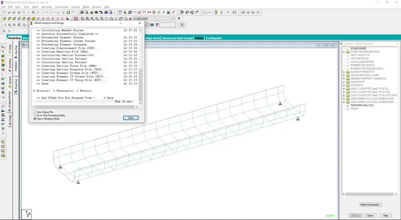
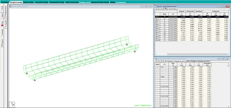
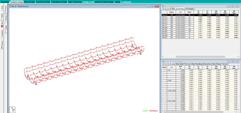
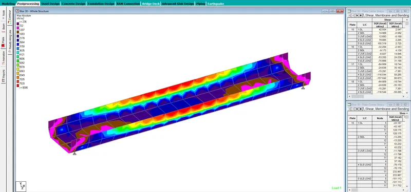
- The maximum BM variation in the plates.
9. How is the longitudinal analysis of open web structure of U girder performed, final design bending moments and axial stresses are extracted? Explain the software procedure for extracting the same.
Ans:
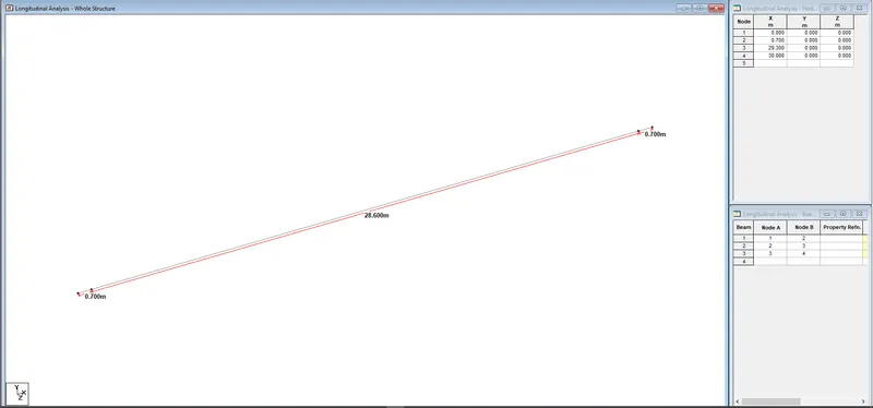
- First of all a line model is to be created by starting the co-ordiante from 0,0 & 0 to 30,0 & 0 for the full length of the span.
- Property as prismatic general for beam is to be defined as calculated.
- Property applied to the whole model.
- Support as pinned support defined and assigned to the concerned node.
Loads and Definations
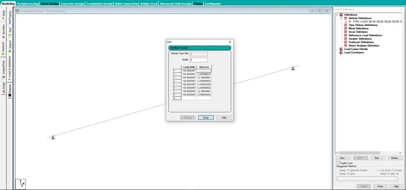
- The metro load is defined in the definations.
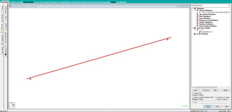
- Dead load will be added as self weight with factor Y-1.
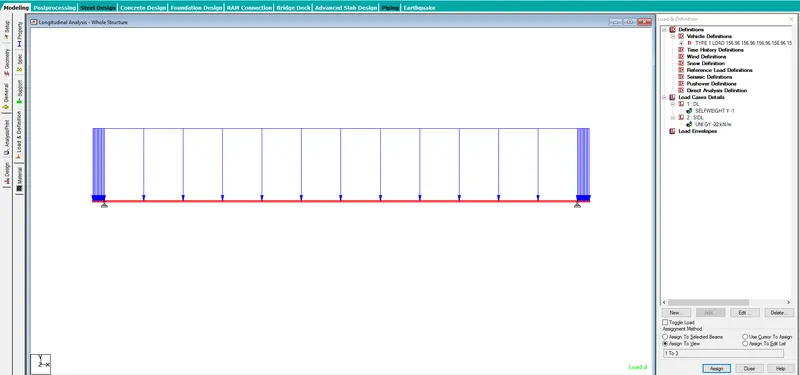
- SIDL is applied with the magnitude of -22KN/m
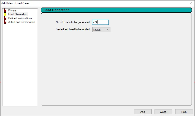
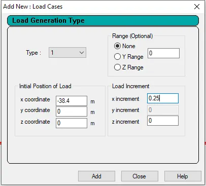
- For live load, no. of loads to be generated = 38.4+30 = 68.4/0.25 = 274
- Generation of load in X direction.
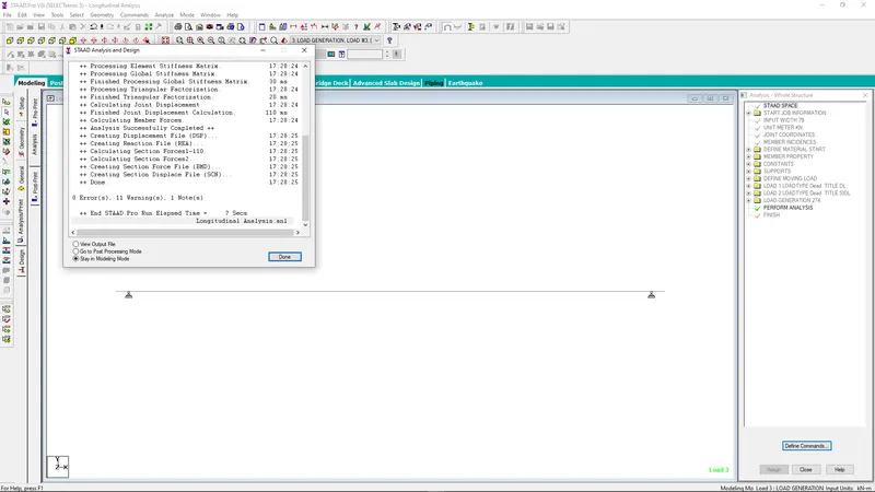
The model is being analyzed and results as 0 error.
Results
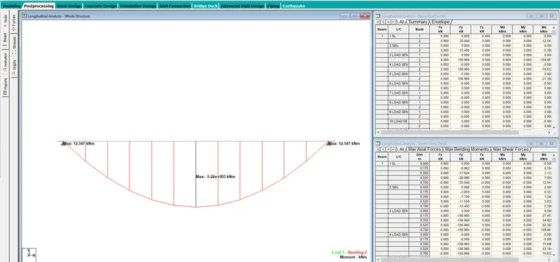
- The maximum BM due DL.
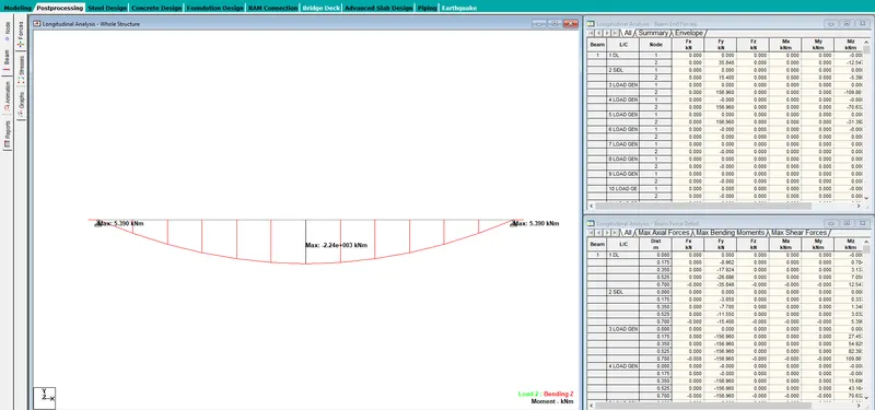
- The maximum BM due to SIDL
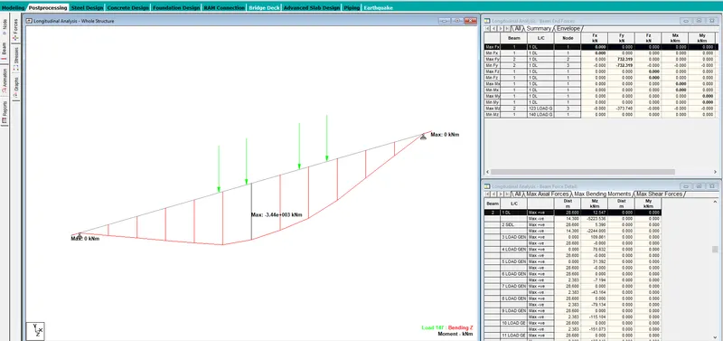
- The maximum BM due to LL
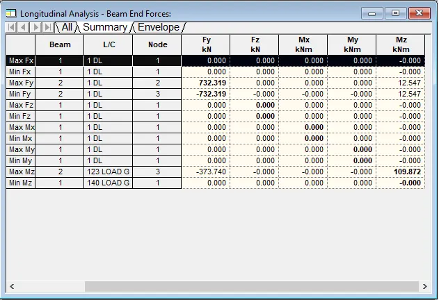
- Summary