Centrifugal pump design and analysis
Aim: To Design a centrifugal pump and analyze how the pressure ratio i.e., outlet total pressure by inlet total pressure, affects the mass flow rate at the outlet.
Procedure:
- Firstly, designed a centrifugal pump with an impeller of 8 blades.
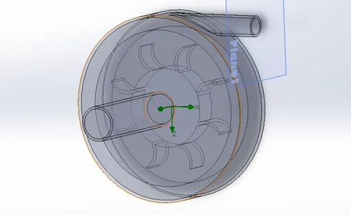
- To simulate the rotation of the impeller it is necessary to create a casing around the impeller. By using this casing, we can denote the rotating regions with a certain angular velocity while performing the flow simulation.
- Created a new flow simulation for the centrifugal pump with a boundary condition of environmental pressure at the inlet and velocity at the outlet.
- Performed a parametric study to know how the outlet velocity impacts the total inlet pressure and outlet total pressure.
Results:
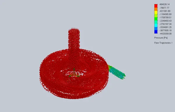
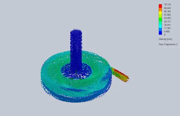
Pressure and velocity flow trajectories at different outlet velocity
- Outlet velocity 10m/s
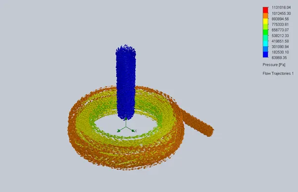
2. Outlet velocity 20m/s
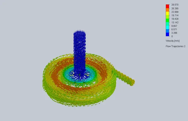
3. Outlet velocity 30m/s
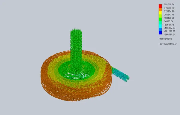
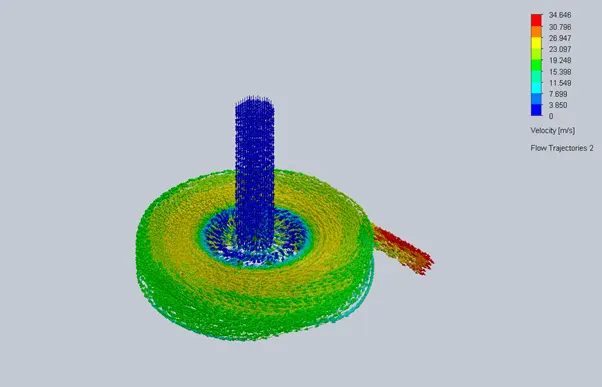
4. Outlet velocity 40m/s
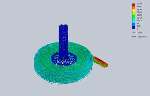
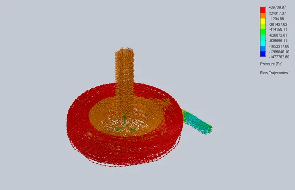
5. Outlet velocity 50m/s
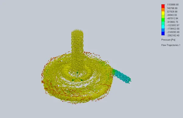
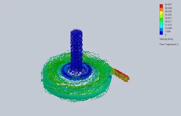
- Outlet velocity 60m/s

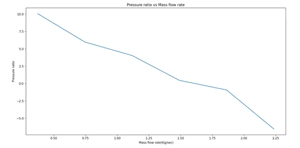
Conclusion:
- From the flow trajectory pictures at the inlet, the pressure is higher compared to the outlet due to which velocity at the inlet is lower than the velocity at the outlet.
- From the performance diagram, it is pressure ratio is inversely proportional to the Mass flow rate as the mass flow rate increases the pressure ratio of the pump decreases.