Boeing-747 _ Final_Project of Boeing
PROJECT REPORT
TITLE:- Design Of Boeing 747-8 using Solidworks.
OBJECTIVE:- The main objective of this project is to make individual part models of the Boeing-747 and then Assembling it in an assembly file.
INTRODUCTION:- This Plane is developed by Boeing Commercial Airplanes, and it is the latest version of the 747. The Fuselage of the plane is streched by 18 feet (5.5m) to 250 feet (76m) making it the longest airlines.
DESIGN METHODOLOGY:-
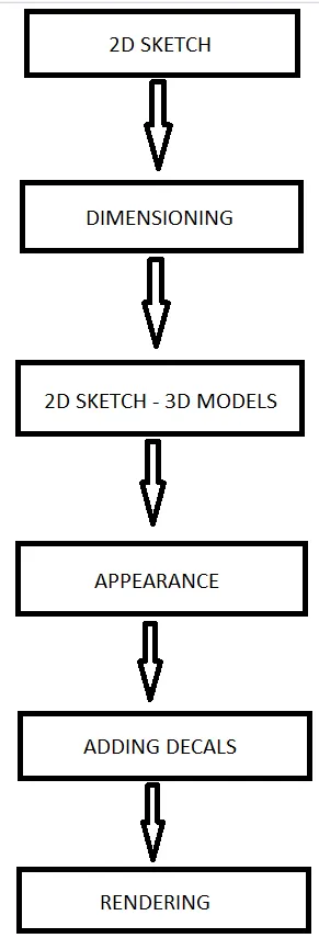
COMMANDS USED FOR MAKING BOEING-747:-
1. Solid Modelling:-
a. Boss-Extrude is used for converting 2d drawing into 3d object by adding materials into the drawing.
b. Boss-Revolve converts 2d sketches into 3d objects by revolving the profile around the mentioned axis.
c. Swept-Boss makes a solid body by sweeping a profile over a sweep path.
d. Lofted-Boss is used for making solid bodies by connecting two different profiles.
e. Cut-Extrude is used for removing material from a solid body.
f. Cut-Revolve removes material by revolving one or more profile around a centerline.
g. Fillets gives radius to the edges of the solid body.
h. Chamfer makes the corners of the solid body flat by the mentioned value.
i. Linear-Pattern is used for creating multiple instances of one or more features along a linear path.
j. Circular-Pattern is used for creating multiple instances of one or more feature along a circular path.
k. Shell converts a solid body into a hollow body with some thickness by removing material from the inside.
l. Mirror creates the selected feature about the axis in a mirrored form to make a solid.
m. Split-Line tool projects an entity to surfaces, or curved or planar faces. It divides a selected face into multiple separate faces.
n. Projection-Curve creates a 3D curve that represents the intersection of two extruded surfaces generated by creating sketches on two intersecting planes.
o. Dome makes a sperical extrude at the faces.
p. Draft is used for tapering of a surface with respect to the reference we selected.
q. Flex is used when we want to bend, twist, taper or to strach our model at a particular degree, this effects the whole body.
r. Move/Copy Body lets you move or copy the selected body anywhere in the 3d space.
s. Keep/Delete Body lets you delete or keep the selected body in your model.
2. Surface Modelling:-
a. Surface-Extrude is used for making 3d surfaces by adding some material into it.
b. Surface-Revolve makes a surface by revolving one or more profile around a centerline.
c. Swept-Surface creates surface by sweeping the 2d profile along a sweep path.
d. Lofted-Surface is made by joining two edges or profile, we can use guide curves if needed to.
e. Filled-Surface constructs a surface patch with any number of edges within a closed boundary.
f. Offset-Surface creates a copy of the selected surface at the mentioned offset distance.
g. Ruled-Surface creates surfaces that extend out in a specified direction from selected edges.
h. Fillets gives radius to the edges of a surface.
i. Delete-Face is used for deleting the selected surface from the part.
j. Extend-Surface creates an extended surface of the selected edge by some value.
k. Surface-Trim is used for removing the extra surfaces we dont need.
l. Knit-Surface is used for knitting/joining two or more surfaces.
m. Split is used to create multiple parts from an existing part.
n. Thicken is used for applying some thicknedd to a surface by adding some material into it.
o. Boundary Surface lets you create surfaces that can be tangent or curvature continuous in both directions and you can also trim the unwanted parts.
p. Cut With Surface helps you cut a solid model by removing material with a surface or plane.
DISCRIPTION:-
- "Blueprint Setup" was created by inserting blueprints on each plane using sketch-picture command.
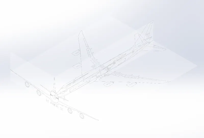
- "Fuselage" is the base body of the airplane. It is like a long hollow tube that holds everything together. Cockpit where the pilot sits in an airplane is at the front of this fuselage. Features used for making this body are, Surface-Loft, Mirror, and Knit-Surface.
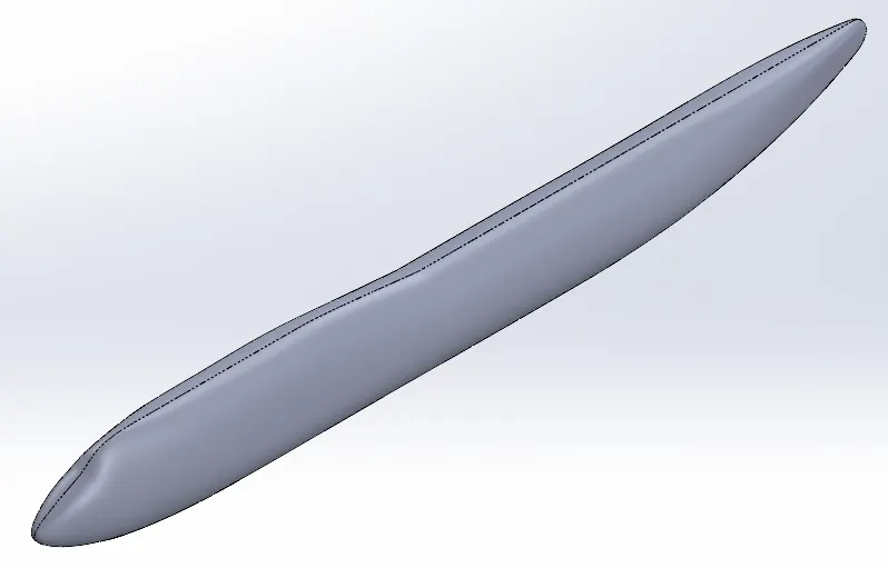
- "Belly Fairing" is a structure whose function is to reduse drag. It is located under the fuselage at the center it can also carry some extra cargo. Features used for making this body are, Boss-Extrude, Fillets, Mirror, & Combine.
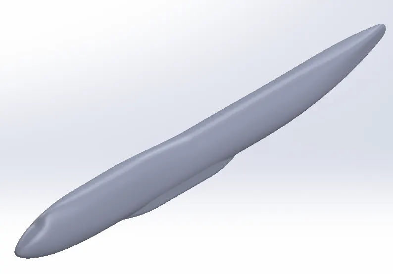
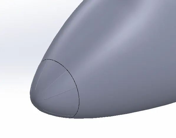
- "Nose Cone" is located at the front tip of the fuselage. It is conicaly shaped to modulate the incoming airflow and minimize aerodynamic drag. Features used for making the come are, Split-Line, Surface-offset, Thicken, FIllets, Mirror.
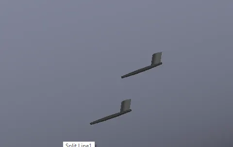
- "Pitot Tubes" are basically a flow measuring device used to determine the speed of an aircraft. Features used for making this tubes are, Boss-Extrude, Fillets, Revolve, Chamfer.
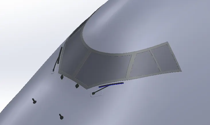
- "Cockpit" this is where all the Controls for flying the plane has mounted. There are cockpit windows for the pilots to have a clear vision forward and wipers for cleaning the windshield , there is a cockpit hatch for emergency exits. Features used for making the cockpit are, Split-Line, Thicken, Surface-Offset, Boss-Extrude, Combine, Fillets, Chamfer.
- "Doors & Hatches" there are a total of 6 doors on each side of the boeing747. There is a total of three hatches for cargo compartment which are at the right side of the fuselage.
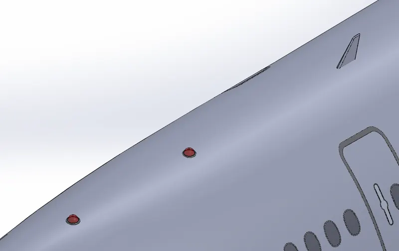
- "Lights & Antennas" Lights are used for landing at night, safety for midair colision and for the interior of the aircraft. There are different types of antennas on an airplane such as , Communication antennas, GPS Antennas, Navigation Antennas, Radio Antennas, UHF Antennas. These models are created using Extrude Boss, Boss-Revolve, Fillets, and move commands.
- "Auxillary Power Unit" is located at the back of the Fuselage. It is like a small jet engine . An APU can be started using onlt the aircraft battery and once it starts it will provide electrical power to the aircraft. There is also a Backlight Located below the APU. Features used for making this body are, Extrude-Cut, Bose-Extrude, Shell, Fillets, Chamfer, Mirror, Thicken, Offset Surfaces.
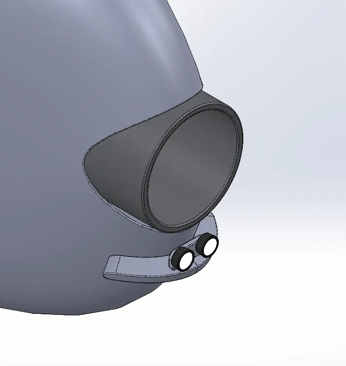
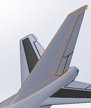
- "Vertical Stabilizer" is located at the tail of the fuselage. It is a component that is designed specifically to minimize side slip. It is also called a rudder Which helps pilots control the plane.
- "Horizontal Stabilizer" is used to balance the aircraft at the longitudinal side. The wings at the horizontal Stabilizer allows us to change the force excerted by the downward air for lifting the aircraft up or changing its direction longitudinally. Features used for making the stabilizers are, Lofted-Boss, Fillets, Projected-curves, Split, Boss-Extrude.
- "Wings" develop the major portion of the lift. it is constructed in such a way that i can hold its aerodynamic shape under the extreme stresses of combat maneuvers or wing loading. Flaps are mounted on the downward edge of each wing. The Airelons controls the rolling movement along the leteral axis of the aircraft. features used for making the wings are, Projected-Curves, Lofted-Boss, Split, Split-line, Fillets, Thicken, Offset-Surface.
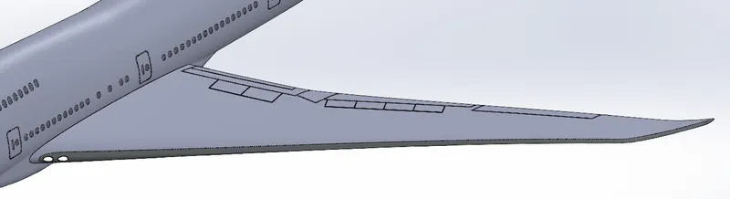
- "Flap Track Fairings" it is secondary structure whose function is to provide an aerodynamic cover to reduce drag. plane has a total of 8 flap track fairing , 4 on each side. features used for making this body are, boss-Extrude, Fillets, Chamfer, Mirror.
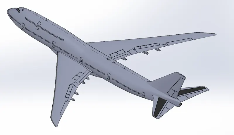
- "Landing Gear Hatches Closed And Open", To reduse drag in flight the pilot retract the wheels after the lift-off into the fuselage, The hatches are operated electricaly as well as hydralically. Features used for making the hatches are, Boss-Extrude, Thicken, Mirror, Plane, Surface-Loft, Thicken.
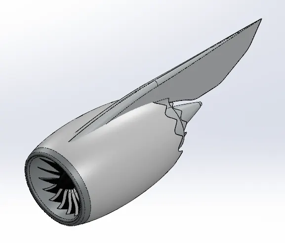
- "Engine" is the part that is responsible for the forward thrust of the plane. they are internal combustion engines. Turbofans are more efficient than turbojets at subsonic speed. at high speed the frontal area generated more drag. Features used for making this body are, Bose-Revolve, Extrude-Cut, Shell, boss-Extrude, Fillets, Chamfer, Draft, Revolve-Cut, Split.
- "Nose Gear Assembly" is made up of Nose Gear Base, Wheel, and Nose Gear Suspension arm. All the Models where Created seperately and then assembled in an assembly file.
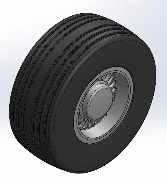
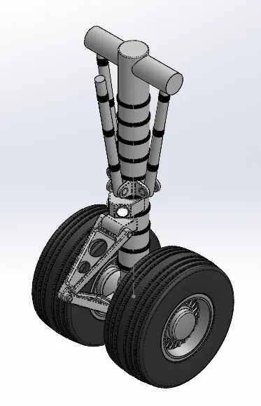
- "Main Landing Gear Assembly" is made up of main gear base, Two main gear suspension arm and four wheels. they where also modeled seperately and then assembled in an assembly file.
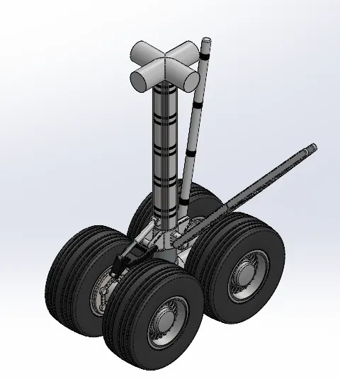
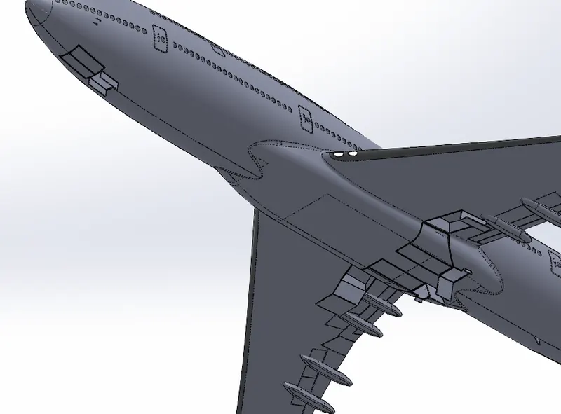
SCREENSHOTS OF THE ASSEMBLY MODEL:-
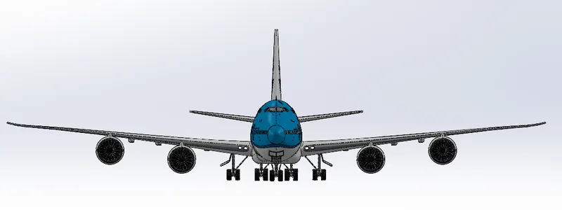
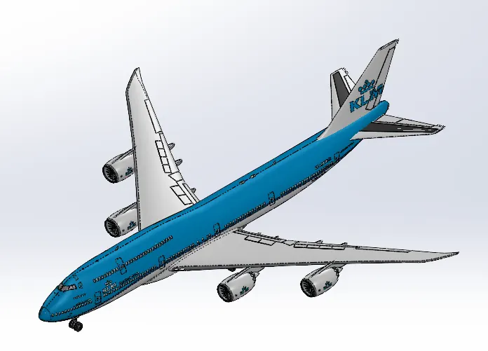
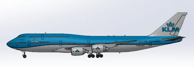
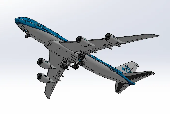
RENDERED IMAGES OF THE PLANE ASSEMBLY:-
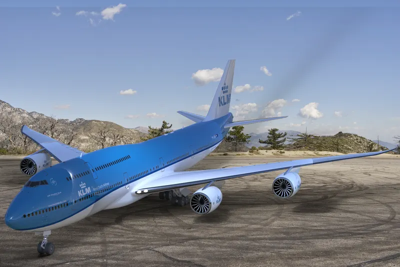
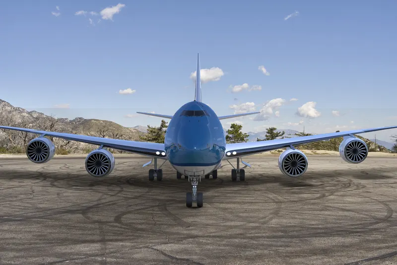
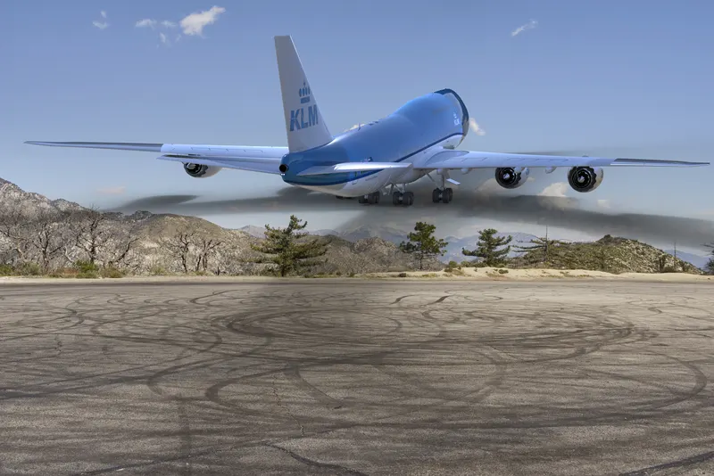
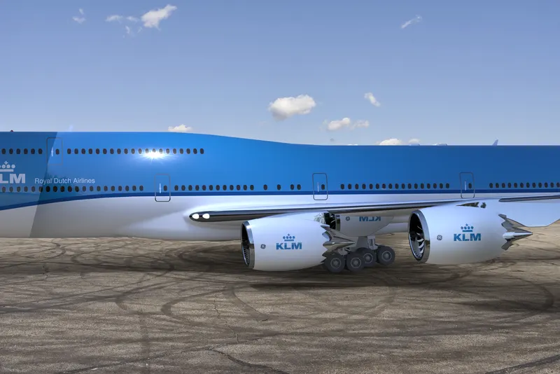
CONCLUSION:- In this project various parts were created using various commands and then assembled in a single assembly file for the final model and then we did some rendering for making a realistic images which was done using photoview 360 adn solidworks visualize.