Boeing-747 _ Final_Project
TITLE OF THE PROJECT : Boeing 747-8
OBJECTIVE : The main objective of the project is to design the boeing 747-8 by using solid works part modelling and the surface modelling tools.
ITRODUCTION :
The Boeing 747-8 is a wide-body airliner developed by Boeing Commercial Airplanes, and the largest variant of the 747. After introducing the 747-400, Boeing considered larger 747 versions as alternatives to Airbus's proposed Airbus A3XX. The stretched 747 Advanced was launched as the 747-8 on November 14, 2005, for a market forecast of 300 aircraft. The first 747-8F Freighter performed its maiden flight on February 8, 2010, and the passenger 747-8I Intercontinental followed suit on March 20, 2011. The cargo version was first delivered in October 2011 and the airliner began commercial service in June 2012.
Its fuselage is stretched by 18 ft (5.6 m) to 250 ft (76.3 m), making it the longest airliner until the 777X-9 which first flew in 2020. While keeping its basic structure and sweep, the wing is thicker and deeper, holding more fuel, and wider with raked wingtips. Powered by the more efficient General Electric GEnx turbofan of the 787 Dreamliner, its maximum take-off weight (MTOW) grew to 975,000 lb (442 t), the heaviest Boeing airliner. The Freighter version has a shorter upper deck and can haul 137 t (302,000 lb) over 4,120 nmi (7,630 km). The airliner version can carry 467 passengers in a typical three-class configuration over 7,790 nmi (14,430 km). As of February 2022, it has 155 firm orders: 107 freighters and 48 passenger airliners.
DESCRIPTION:
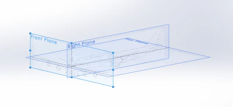
BLUPRINT SETUP is done by inserting the sketch picture to the right plane , topplane and then front by providing the required dimensions to match the planes.it is also helpfull in understanding how to design the boeing 747-8.
fusegae;
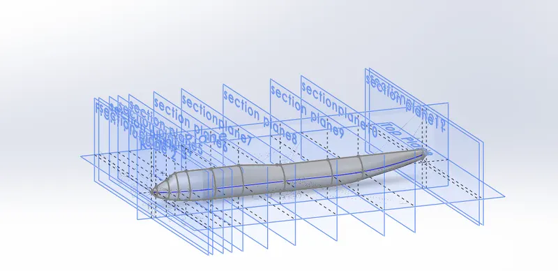
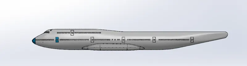
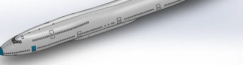
fuselage is the cenral body of the aeicraft that cosist of cockpit and the passengers area . it varies according to the aircraft . in jet figher it have only cockpit smaller portion to accomodate the pilot and extra one person.fuse lage is design by creating the 11 planes and projeted curve .atlast lofted surface is used to crate the fuselage.
belly fairing
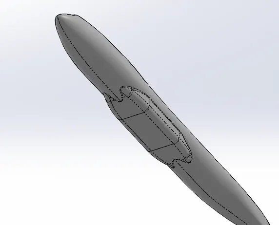
belly fairing is the middle portion to hold the fuel tank and then corgo. belly fairing is spilt command extrude option mirror and combine command.
nose cone
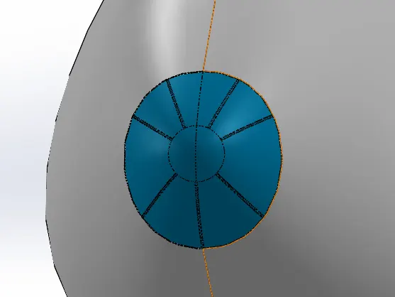
nose cone front portoin of the aeroplane used for aero dynamic drag. it is done by split line operation and the sweepcut operation to form the design. atlast fillet is applied to provide smooth edges.
pitot tubes;
pitot tube is used to measure the speed of aircraft and then used to measure then alitude. it is designed by sketch in the topplane for direction of extrude and then axis is created for sweep operation. plane is created for drawing the line to match the sweep operation.and then mirror option along the right plane to mirror the pitot tube. chamfer is provided for cone shaped structure.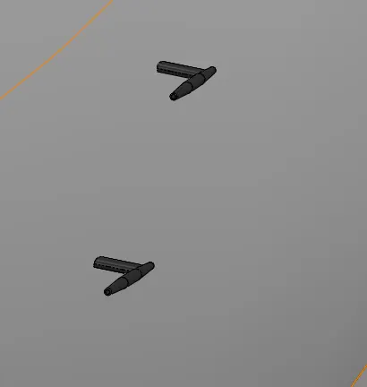
cock pit windows ;
cock pit window is made that strong it is able capable at any circumstance . it is made of stong material and chemicals. cockpit window is the area where the pilot can looks ouside to control the aircraft.It is designed by five split line operation and then thicken operation. later apperances is provided according to the glass.
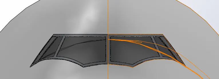
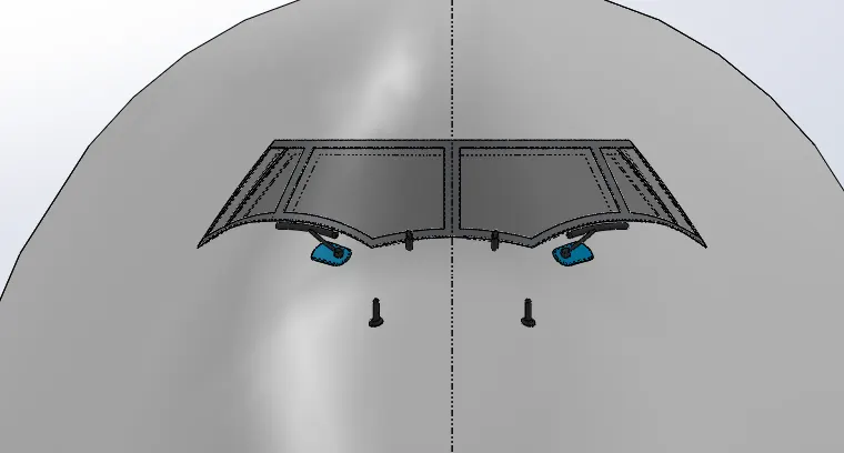
winshield wipers : wind shield wipers is provided to wipe the mist ,fog waterdroplets that spread over the cockpit windows. it is designed by providing shell operation to the fuselage . and then extrude diretion sketch is provided. for extrude and then sweep cut operation is used to swwep the wiper. atlast mirror option is dne along the right plane to copy the wipers to the another face.
passenger window;
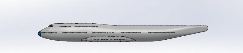
passenger window is used to watch outside atmosphere .passenger window is created as an seperate block in a new partfile . and then it is inserted in the boeing 747-8 . then it is multiplied by linear sketch pattern. according to the need and then distance.
Doors and hatches:
doors and hatches is designed as same approach as windows. split line operation is used to desihn and then hatche is provided on the side for emergency exit.
lights and antennas;
lights and antennas is designed on the top of the aircraft for sending and receiving the signals.it is designed by revolve option lineasr pattern ,surface offset and then thicken option . body copy move option is done to move the crated design whereever needed.
auxillary power unit :
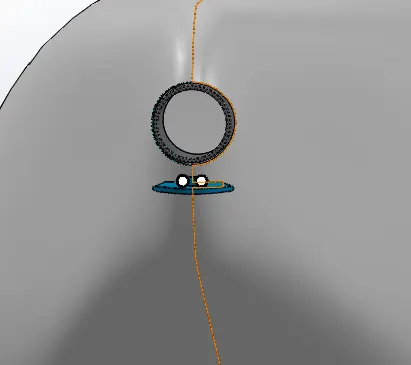
auxillary power unit is designed on the back side of the aircraft to send the eletrical signals to the aircraft appliances. it is done by extrude cut ,split line dome option is used designing the lamps. and then appearances provided for the lamps.
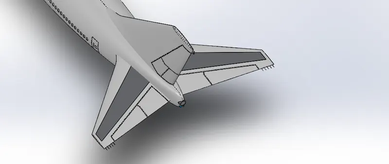
vertical stabilizer ;
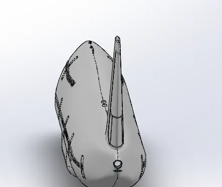
vertical stabilizer is designed on the tail of the aircraft .vertical stabilizer is designed by boss extrude ,splitline operation and then extrude cut thin . and then fillet is applied for getting smooth edges.
horizotal stabilizer:
horizontal stabilizer is designed by projeted curve and using the plane it is made into a solid body by lofted boss bass.and then variable fillet is used and then boss extrude splitline operation , surface offset and then thicken operations.
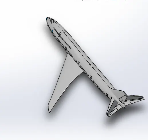
wing: wings are designed in such a way it can hold aircraft in the air. wing is designed by by projected curve and then surface loft operation. and then the surface offset and surface cut option is used to cut extra portion inside the fuselage.
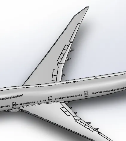
flaps and aielerons : flaps and aielerons is done by split line option and then surface offset and thicken option. later fillet is applied for getting smooth edges. it is also done by using sketch picture according to the line and shape is created later converted into split line by using split line operation.
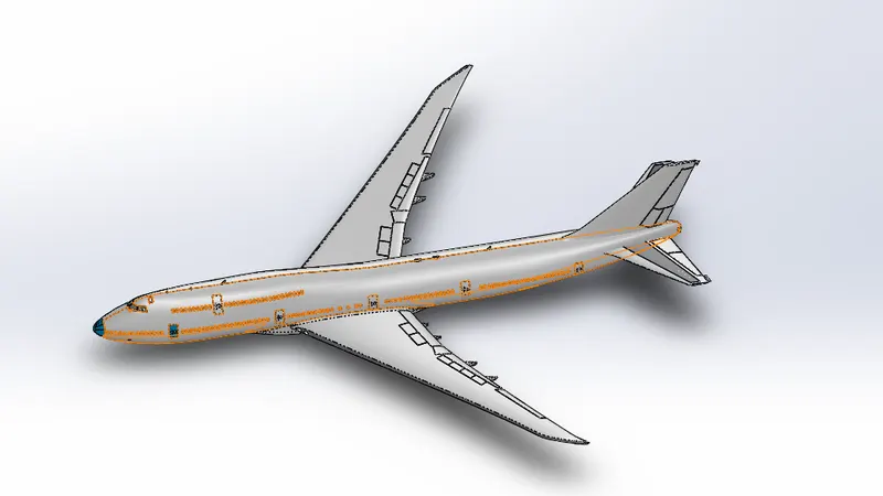
flap track and fairings.
flap track and fairing by using split line operation and then boss extrude operation. body copy move option is done to move the created solid body to required places.
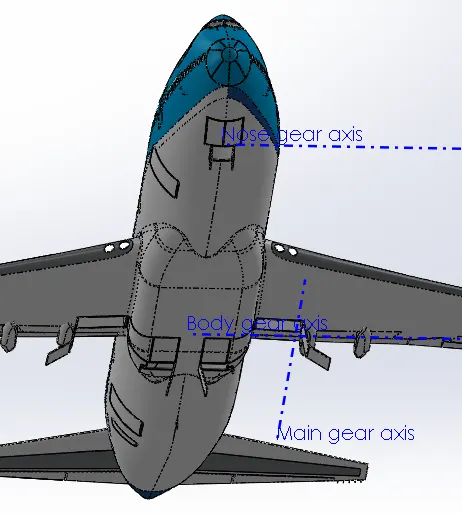
landin gear axis.
This sketch is creted as referrence acis to place the solid body.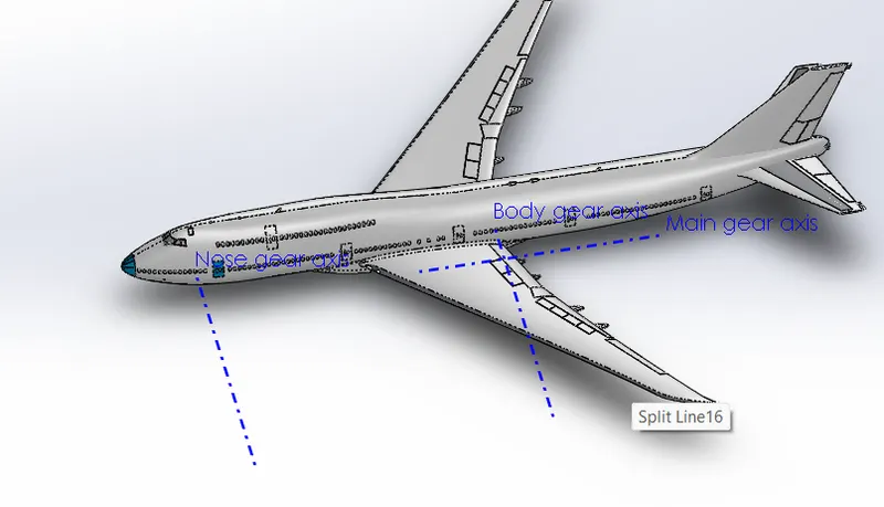
landing gear hatches closed and open :
landing gear hatches closed and open is given below the fuselage for wheel to expand and retract during take off and take in.
this one is done by split line operation and then surface offset and then thicken operation.
wheel
wheel is done in seperate part module . as a seperate part and then assembled . this one is done by revolved boss bass. and then revolved cut ,circular sketch pattern. 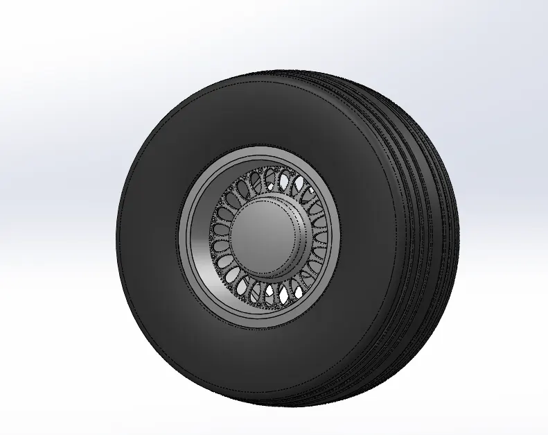
nose gear base
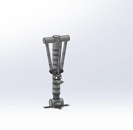
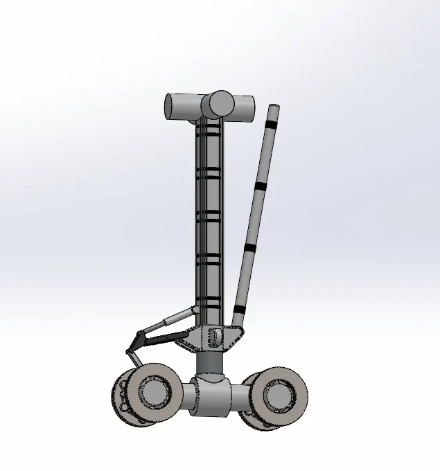
nose gear base is done by extrude boss bass, linear sketch pattern , extrude cut , mirror option sweep option and then combine command.
main gear base
main gear base is done by extrude boss bass extrude cut linear sketch pattern sweep option split command and then by combine command operation.
engine :
engine is designed by using the sketch picture. tools such as circular pattern extrude cut is used to design the engine.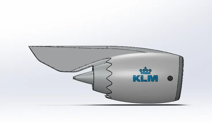
livery .
lvery is the appearances is provided according the manufatures and then brand name.
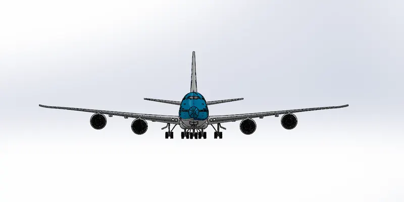
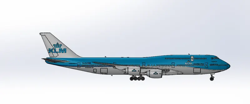
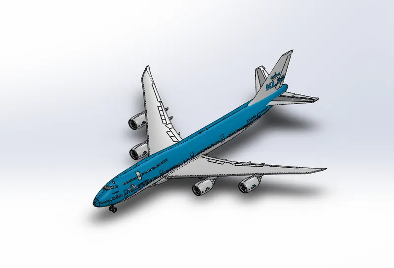
conclusion ; hence the boeing 747-8 is designed using the various part modelling and surface modelling tools.