Boeing-747 _ Final_Project
Boeing 747
OBJECTIVE:
Modelling, assembling and rendering a Boeing 747 using surface modelling and solid modelling techniques in solid works.
Types Of Commands:
- Sketch
- Feature
- Surface
- Assembly
Sketch: These commands used to create the 2D or 3D sketches and concerned dimension and the geometrical relations to define the sketch.
Features: These are used to generate the 3D parts the options such as revolve, extrudes and swept body and loft. The generated 3D parts are modelled with options such as fillet, chamfer and extrude cut, revolve cut and sweep cut.
Surfaces: Surfaces are formed by applying various surface features like extrude surface, revolve surface, loft surface, sweep surface, extend surface and ruled surface etc. Again, the generated surfaces are edited with the options trim surface and thicken surface.
Assembly: Select the components are assembled by applying the mate options such as coincident, concentric, distance, parallel etc.
- Sketch Commands:
Creating a model begins with a sketch. Based on the sketch, we can create features. Sketch should be completely defined by applying the geometric relations and dimensions. In 3D sketch, we can snap to directions X, Y, and Z, and constraints are applied along X, Y, Z respectively. When sketching on a plane, we can snap to the horizontal or vertical directions in the plane, and constraints are applied to the Horizontal and the Vertical.
- Smart Dimension - Creates a geometrical dimension for any selected sketch entity.
- Point – It is a 1D element, it inserts a point or vertex into a sketch entity. This cannot be deleted if it is part of sketch endpoint or centre point.
- Line – Generates the lines which can be drawn horizontally, vertically or at any angle.
- Circle – Generates the circular drawing on the graphics area. There are two circle tools which are “Centre circle” and “Perimeter circle”.
- Rectangle – Generates rectangles or square with a centre point at a selected angle there are rectangles like cantered rectangle, corner rectangle. Parallelogram sketches a standard parallelogram.
- Spline – splines can be created with number of midpoints depending upon the complexity of the curve. A 2or 3 dimensional curves defined by a set of control points. Points within a spline can be added or deleted.
- Sketch Fillet - A tangent arc in between two sketch entities can be created with a radius.
- Text - It can be used to write the text necessary wherever required either it’s a plane or face of a model.
- Convert Entities - Copy a sketch entity on plane, it must have an original sketch entity already drawn and selected to use this tool.
- Offset Entities – Creates a sketch entity to a specified distance from the original entity. Must have an original sketch entity already drawn and selected to use this tool.
- Sketch Picture - Insert an image file into the background of a sketch. This allows the user to 2D sketches based on the image. Use the sketch picture property manager to alter the inserted image.
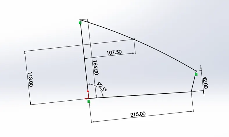
-
Figure 1: 2D Sketch generated in solid works
The sketch is shown in black colour which indicates that it is completely defined. The geometric relations like coincident, parallel, equal, vertical and horizontal are shown in the green colour icons as shown in the figure 1.
- Feature commands:
Some sketch-based features are shapes such as extrude, extrude-cut and holes. Other sketch-based features such as lofts and sweeps use a profile along a path. Applied features include fillets, chamfers, or shells they are applied to existing geometry using dimensions and other characteristics to create the feature. Then we add applied features. It is possible to create a part without sketch-based features.
- Extruded Boss/Base - An Extruded Boss/Base feature will allow us extrudes the sketches to generate prismatic solids.
- Extruded Cut – It is a tool to remove material by projecting a sketched section normal to the sketch plane.
- Split - Lines are used to divide model faces into two. Split lines are created like any other sketched feature. They can be one or more connected sketch entities. They must be oriented so that they will pass through model faces when projected normal to the sketch plane.
- Dome – It can be of two types elliptical and spherical. It can add one or more domes to the selected planar or non-planar faces. The software calculates the distance using the radius of the arc as a basis for the dome.
- Fillet and chamfer- used to modify the edges into fillets and chamfer with required dimensions.
- Plane- It is used to generate the planes at different orientation in which the required sketch is to be drawn.
- Project Curve - Select Bi-directional to create a projection that extends on both sides of the sketch. The curve can be used as a path for a sweep.
- There are two types of projected curves. Sketch on Sketch which uses two sketches to make a single curve and Sketch on surface uses a sketch to project on a surface.
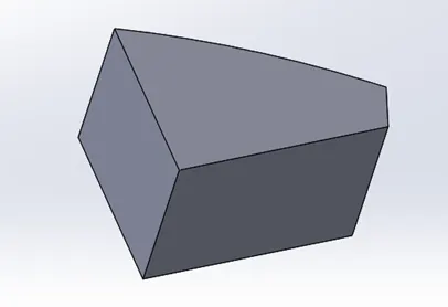
-
Figure 2: Extruded part
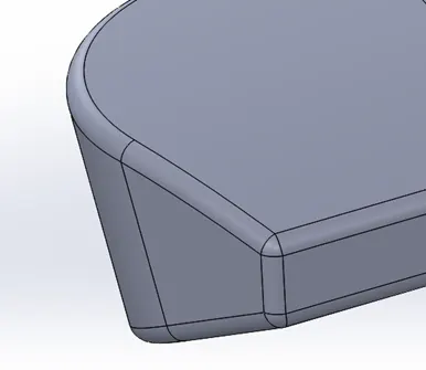
-
Figure 3: Fillet applied at the edges of the extruded part
The previous sketch in figure-1 is extruded by using the boss extrude command as shown in the figure-2. Similarly, the extrude cut command is used to remove the solid parts from the generated solid just like the extruding 2D sketch.
- Surface Modelling:
Zero thickness geometry is known as surface. Surface modelling is a method of creating planar or non-planar complex geometry which has zero or negligible thickness. The surfaces are generally used to create models of complex shapes. The conversion of surface models into solid models and solid model into surface is also possible by using the tools available for surface modelling. The surface commands are:
- Lofted Surfaces – Creates a lofted surface between two or more profiles or sketches. Specify start and end constraints and add guide curves to specify the path shape.
- Boundary Surfaces – The boundary surface feature allows to create surfaces that can be tangent or curvature continuous in both directions.
- Extruded Surfaces – Extrudes a sketch or selected sketch contours in one or two directions two create a surface feature
- Revolved Surfaces – Revolves a sketch or selected sketch contours around an axis to create a revolved surface feature.
- Swept Surfaces – It Sweeps a closed profile along an open or closed path to create a surface feature. It uses a tangent plane at the end of the path so that the path is normal to the swept surface.
- Filled Surfaces – Patches a surface within a boundary defined by edges, sketches, or curves.
- Ruled Surfaces – Inserts ruled surfaces in a specified direction from edges. Tangent to surface, Normal to surface, tapered to vector, perpendicular to vector or sweep can be selected.
- Trim Surface – It trims the surfaces where a surface intersects with another surface, a plane or a sketch.
- Knit Surface – It combines two or more adjacent, non-intersecting surfaces into a single surface body. The surfaces must join at an edge. If the resulting knit surface encloses a volume, we can create a solid body from the Property Manager.
- Move/copy surfaces – Moves or copy surfaces about a plane or a sketch.
- Offset Surface – Offsets surfaces using one or more continuous faces. This tool helps us to create an offset surface with gaps.
- Extend Surface – Extends one or more edges or faces on a surface, based on end conditions and extension type.
- Mirror surfaces – A mirror feature is a copy of a selected feature, mirrored about a plane or planar face. A mirror sketch entity is a copy of a selected sketch entity that is mirrored about a centreline. If the original feature or sketch is modified, the mirrored copy is updated to reflect the change.
Figure 3: Fillet applied at the edges of the extruded part
The previous sketch in figure-1 is extruded by using the boss extrude command as shown in the figure-2. Similarly, the extrude cut command is used to remove the solid parts from the generated solid just like the extruding 2D sketch.
- Surface Modelling:
Zero thickness geometry is known as surface. Surface modelling is a method of creating planar or non-planar complex geometry which has zero or negligible thickness. The surfaces are generally used to create models of complex shapes. The conversion of surface models into solid models and solid model into surface is also possible by using the tools available for surface modelling. The surface commands are:
- Lofted Surfaces – Creates a lofted surface between two or more profiles or sketches. Specify start and end constraints and add guide curves to specify the path shape.
- Boundary Surfaces – The boundary surface feature allows to create surfaces that can be tangent or curvature continuous in both directions.
- Extruded Surfaces – Extrudes a sketch or selected sketch contours in one or two directions two create a surface feature
- Revolved Surfaces – Revolves a sketch or selected sketch contours around an axis to create a revolved surface feature.
- Swept Surfaces – It Sweeps a closed profile along an open or closed path to create a surface feature. It uses a tangent plane at the end of the path so that the path is normal to the swept surface.
- Filled Surfaces – Patches a surface within a boundary defined by edges, sketches, or curves.
- Ruled Surfaces – Inserts ruled surfaces in a specified direction from edges. Tangent to surface, Normal to surface, tapered to vector, perpendicular to vector or sweep can be selected.
- Trim Surface – It trims the surfaces where a surface intersects with another surface, a plane or a sketch.
- Knit Surface – It combines two or more adjacent, non-intersecting surfaces into a single surface body. The surfaces must join at an edge. If the resulting knit surface encloses a volume, we can create a solid body from the Property Manager.
- Move/copy surfaces – Moves or copy surfaces about a plane or a sketch.
- Offset Surface – Offsets surfaces using one or more continuous faces. This tool helps us to create an offset surface with gaps.
- Extend Surface – Extends one or more edges or faces on a surface, based on end conditions and extension type.
- Mirror surfaces – A mirror feature is a copy of a selected feature, mirrored about a plane or planar face. A mirror sketch entity is a copy of a selected sketch entity that is mirrored about a centreline. If the original feature or sketch is modified, the mirrored copy is updated to reflect the change.
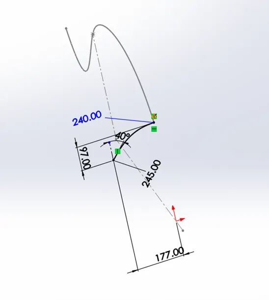
-
Figure 4: Two Different curves on different planes
In the figure 4, the two curves are shown in the two mutually perpendicular planes which are drawn to generate a surface by using the swept surface option. After applying the swept surface command on the two curves, the required surface is generated along the path curve by translating the sketch curve.
-
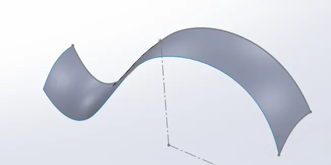
Figure 5: Generated Surface
These surfaces are trimmed to remove the unwanted surface and are knitted to merge into single surface. While knitting the create solid option is available to convert the closed surfaces into solids.
- Assembly commands:
- Concentric- makes the selected surface and the curvy edges concentric
- Coincident- surfaces, edges and corners are coincides by using this command
- Distance- distance is given as constraint between the assembled parts
- Parallel- required edges and surfaces are aligned parallel to each other
- Perpendicular-edges and surfaces are aligned perpendicular to each other
- Tangent- desired edges and surfaces are assembled with the curvy surfaces with tangent relation.
- Lock- constraint the parts completely at their current position and orientation without any other geometric relation with the other parts.
Methodology:
Sketch in required plane of reference
By using the sketches generated in the planes the desired parts are modelled with feature and surface options
After generating the model, required appearances are applied for better view of the model and decals are also applied according to the requirements
The modelled parts are assembled by using the mate commands
The assemble model is rendered to get an attractive view
Modelling:
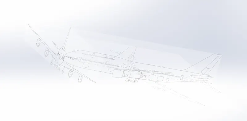
As this modelling consists of complex surfaces, it requires the blueprint images to draw the concerned splines.
Blueprint- It is setup which represents the reference planes where 2D and 3D sketches are drawn with respect to the transparent blue print photos on the top plane, right plane and front plane.
-
Blueprint setup
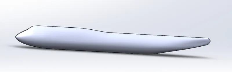
Fuselage is the main part in this modelling, so it is modelled first. The Fuselage is by using the surface loft option. So, the generated fuselage is the surface mode. In order to make it as a solid body, the thicken option is used. Also, the fuselage has many variations in the cross section, so the required plane parallel to the front plane are created. In each plane, the desired cross section is sketched and after lofting the sketches, the resultant surface is mirrored to form a full model of the fuselage.
-
Fuselage
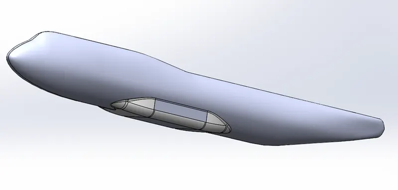
After modelling the fuselage, the Belly fairing is modelled with boss extrusion option. The concerned fillets are given to the fairing and combine add option is used to merge the solids i.e., Fuselage and the belly fairing.
-
Belly fairing
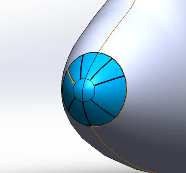
Nose cone part is given with sweep parts as shown in the figure. First the nose cone portion is separated by using the split line option to distinguish the nose part and the for the concerned modelling. The modelled sweep parts are modelled and mirrored and given with the fillets.
-
Nose cone
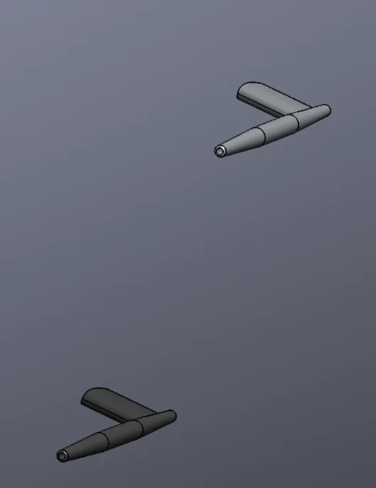
Pitot tubes are modelled by using the boss extrude option and while genrating the solids, the merge solid option is mentioned. The resultant solids are given with the required chamfer and fillet values.
-
Pitot tubes
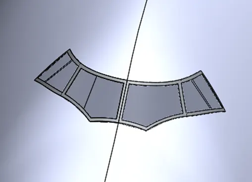
Cockpit windows of the model is modelled by separating the window surface by using the split line option. The separated face is given with the offset surface of 0mm distance from the surface. The generated surface is thickened to convert into solids and the required appearance is given to the widows.
-
Cockpit Windows
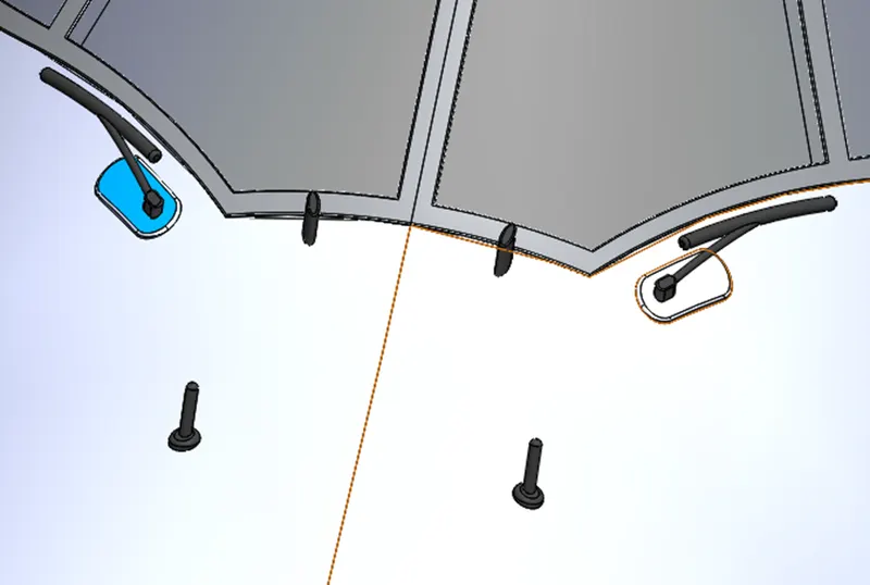
The windshield vipers are modelled with the extrude, sweep and fillet options. The Body-move/copy option is used to place the viper is correct place. The vipers are also merged with the fuselage by using the combine option.
-
Windshield viper
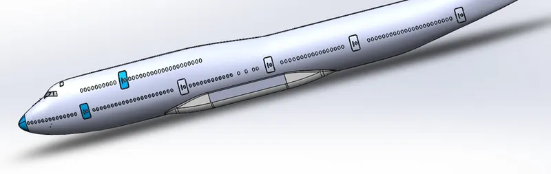
The doors and the windows of the fuselage are first seperated as faces by using split line option. The window faces are given with the offset surface with the 0mm from the window faces. The offseted surfaces are given with the thicken option to form the solids and the requied appearce is given to the windows.
-
Doors and Windows
Similarly, the doors and hatches are modelled in the same way. The linear pattern is used to replicate the doors and hatches in the desired pattern.
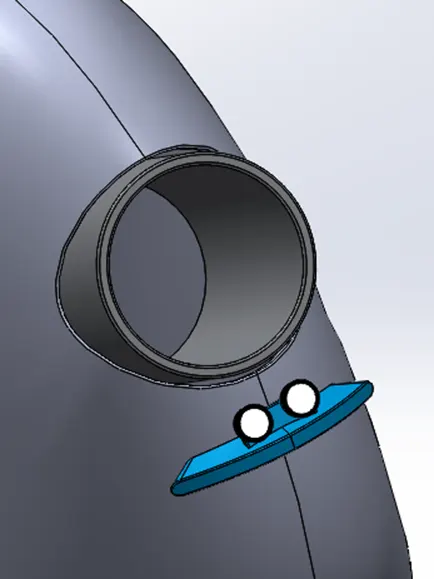
The lights of the fuselage are modelled by using the revolve option and the antenna is generated with the extrude option and is given with the draft angle by using the draft command.
-
Auxiliary power unit
The auxiliary power unit is modelled at the rear side of the fuselage by removing some portion by using the cut extrude. The surface is generated first and it is thickened to form a solid.
-
Vertical and Horizontal stabilizer
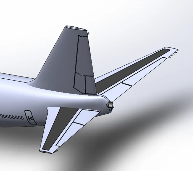
The vertical stabilizer is modelled by using the lofted boss option and is given with the required fillets and the desired portion is cut extruded from the stabilizer with the non-closed sketch and with thin feature on while performing the cut extrude option.
The horizontal stabilizer is generated with surface loft command with projected curves. The projected curves are generated with the help of the blueprints of the front and the top views. The similar cut extrusion process is done on the horizontal stabilizer.
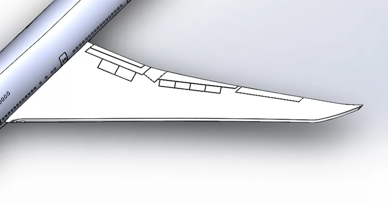
Wings are also generated by using the projected curves by using the top and front blueprints. The projected curves are used as guide curves and the profiles of the wing are considered as profile curve for the lofting.
-
Wing and Flaps
Flaps and ailerons are modelled at the rear end of the wings. The required portion is separated by the split line and the portion is given with the offset surface. The offset surface is given with the thicken option.
Flap track fairing are modelled with the boss extrude command and are given with the required fillets. Body-move/copy option is used to place the bodies in required portion.
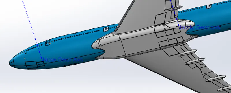
The landing gear hatches (closed) are modelled at the bottom side of the fuselage. The commands used for this modelling is split line, offset and thicken commands. The left portion of the hatches are generated by using the mirrors command.
-
Gear hatches closed
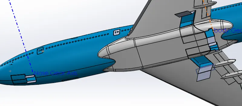
Similarly, the landing gear hatches (open) are modelled by thickening the generated surfaces. Here, the surfaces are generated by using the sweep surface option. If the landing gear hatches (open) folder is suppressed, the landing gear hatches (closed) will be visible.
-
Gear hatches open
The predefined blocks of the text on the aeroplane are inserted in the right plane projected into the surface of the aeroplane. The required appearances are given to the concerned faces.
Assembly:
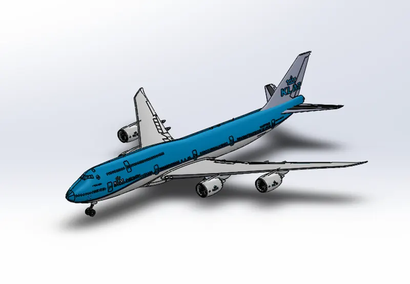
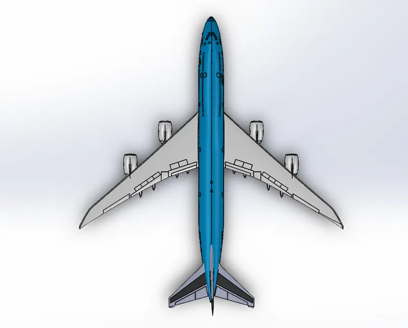
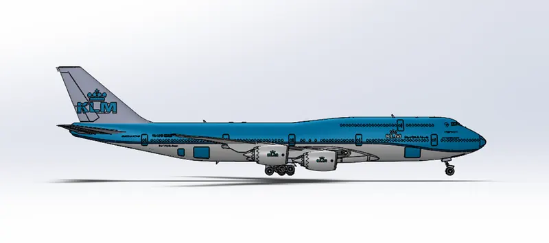
In assemble, the main part i.e., Fuselage is imported first and is fixed at its own position and remaining parts like nose gear assemble and main gear assemble are assembled. After assembling every part, the status of the assemble i.e., undefined, defined and over defined is checked and ensure that it should be defined only when there is any degree of freedom is allowed. The presence of solid of one part into another part is also avoided.
-
Assemble of Boeing 747
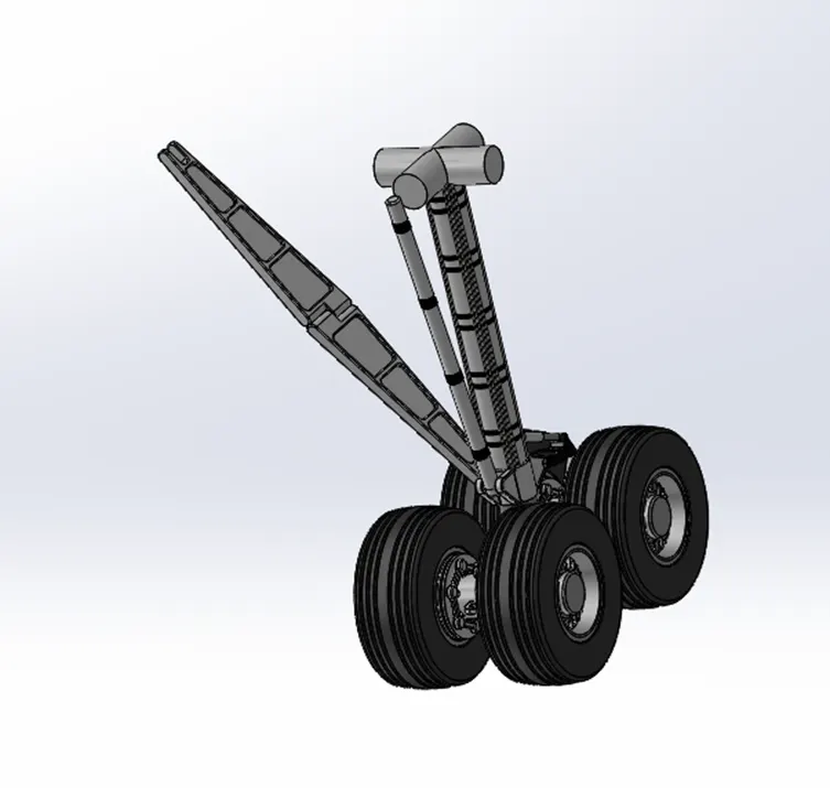
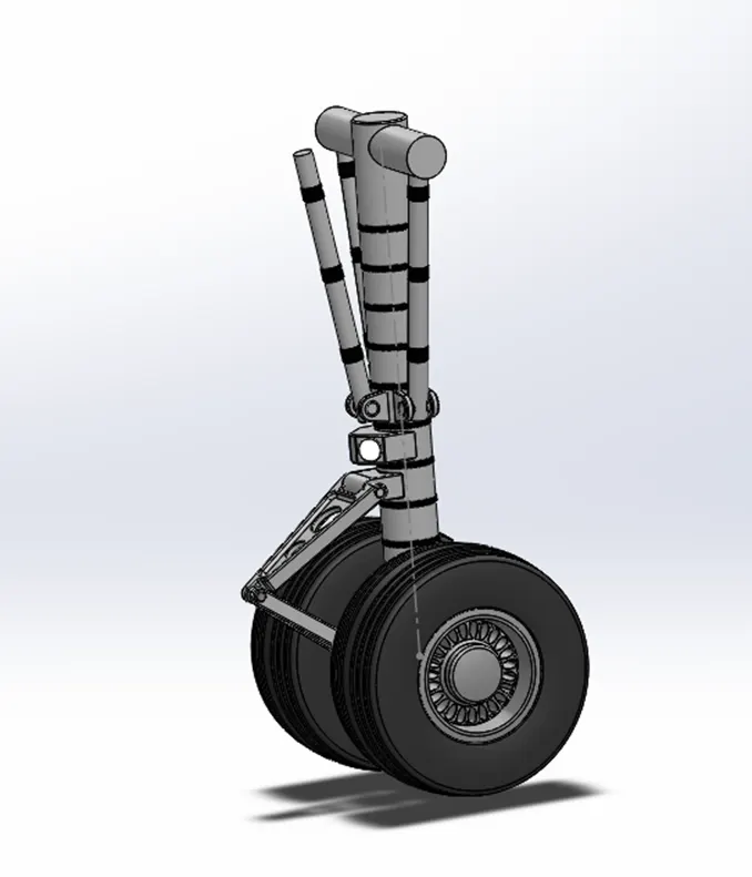
The nose landing gear and main body landing gears are also assembled with the tires and the main base.
-
Main gear assembly
-
Nose landing Gear assembly
Rendering:
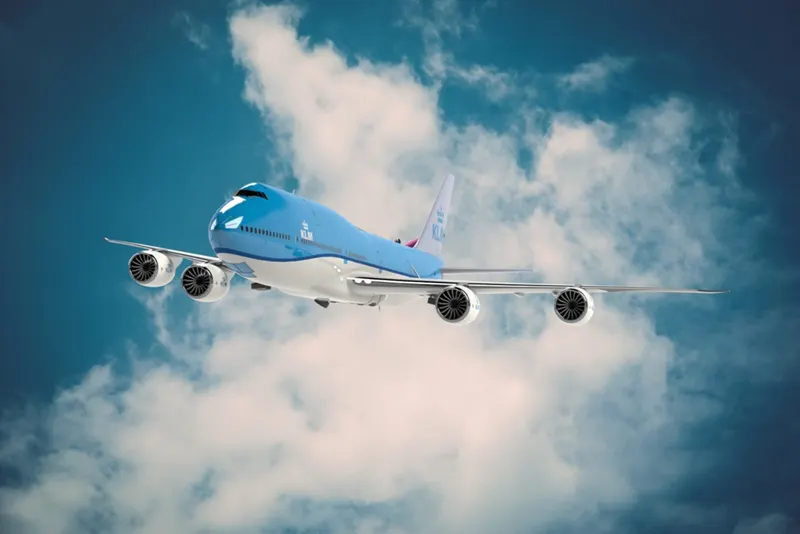
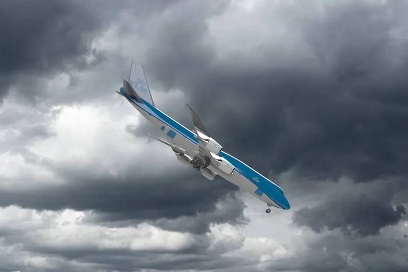
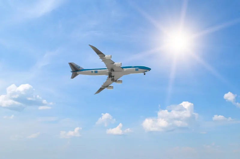
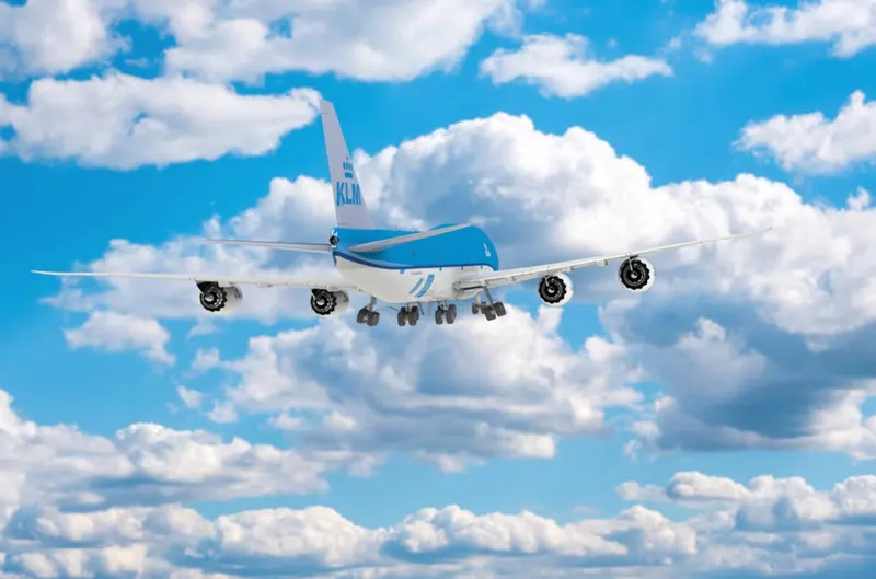
Rendering is done to get the realistic and attractive view of the model. It is done by using different types of lights and the light directions and orientations. Some background images are also used to make the view more vibrant and attractive.

Conclusion:
The parts of the Boeing 747 are modelled with defined sketches and the modelled parts are assembled. The assembled model is rendered to get a realistic view.