Bird Strike - Project - 2
Aim: To simulate Bird strike on aero engine turbine blades concept which is classic nonlinear transient analysis solved using the explicit solver.
Objective: The bird strike is the classic example of the nonlinear transient analysis which is solved using the explicit solver, since the bird strike is common and evidently catastrophic in nature to the aircraft structure. Therefore, the simulation is created to identify the results and observe how the bird strike affects the blades of the aircraft engine.
Procedure:
The given file of the bird strike is downloaded and opened in Ls-dyna.
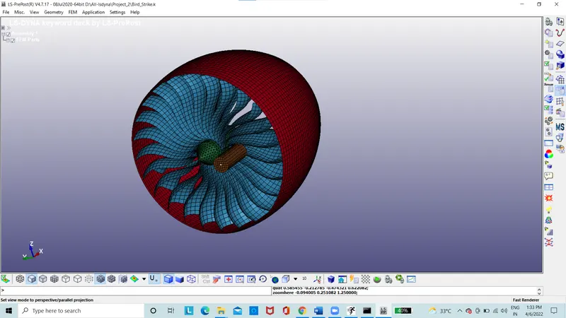
Figure 1: Aero engine and bird model
The aero engine and the bird meshed model are in one file. Therefore, need to separate models of bird and aero engine parts from the downloaded file.
The model of casing is separated by deleting bird, blade and hub.
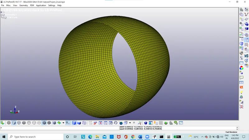
Figure 2: Casing Model
The model of blade and hub is separated by deleting bird and casing.
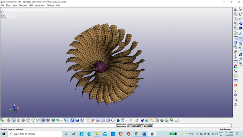
Figure 3: Bade and hub Model
The model of bird is separated by deleting casing, blade and hub.
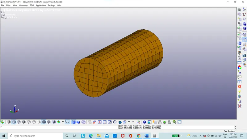
Figure 4: Bird model
The models are now separated which is assigned with section and material to the each of the model.
The section of the casing is assigned with thickness and shell section.
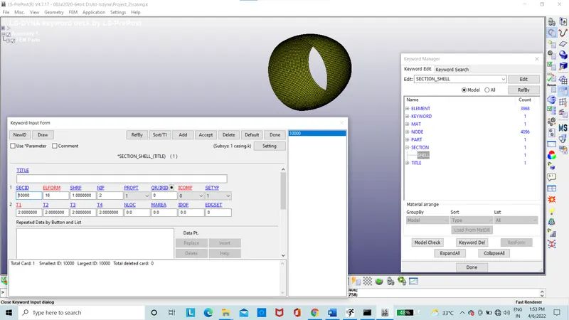
Figure 5: Casing model section
The casing is assigned with the elastic material model.
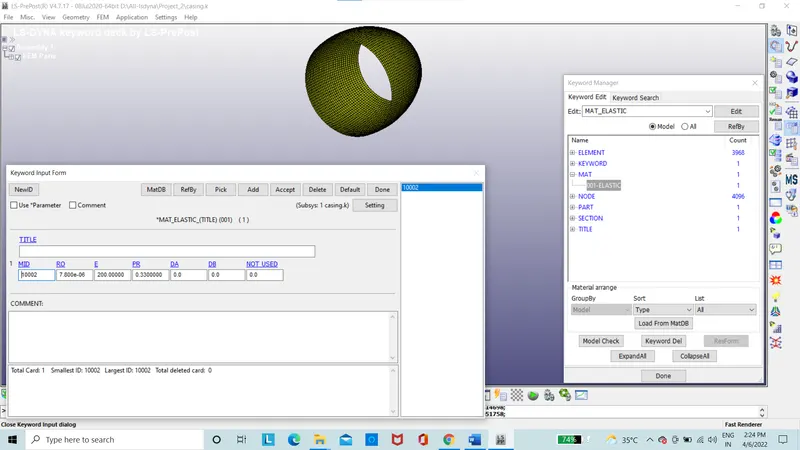
Figure6: Casing model material
The section of the blade is assigned with thickness and shell section.
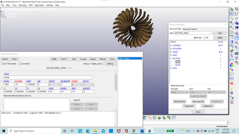
Figure 7: blade model section
The blade is assigned with the given 024 piecewise linear plasticity material model.
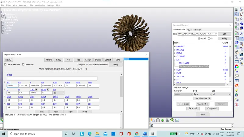
Figure 8: blade model material
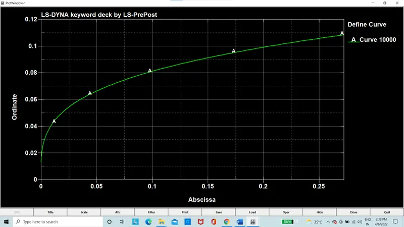
Figure 9: Material curve
The section of the Hub is assigned with solid section.
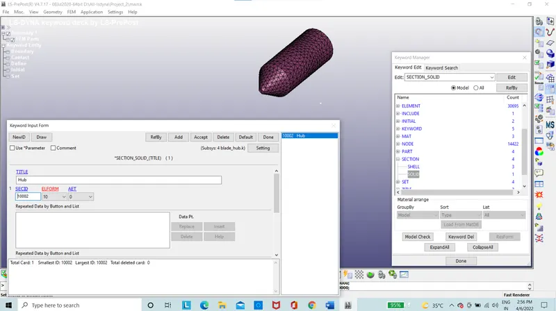
Figure 10: Hub model section
The Hub is assigned with the given 024 piecewise linear plasticity material model.
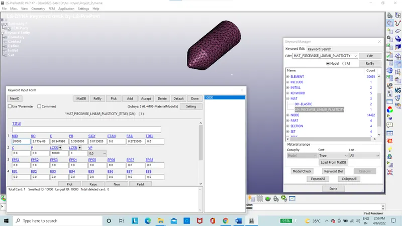
Figure 11: Hub model material
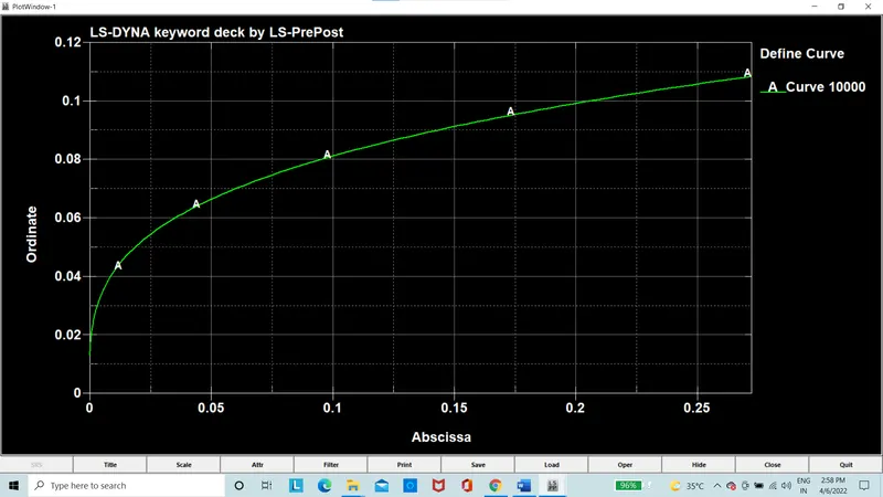
Figure 12: Material curve
The section of the bird is assigned with thickness and shell section.
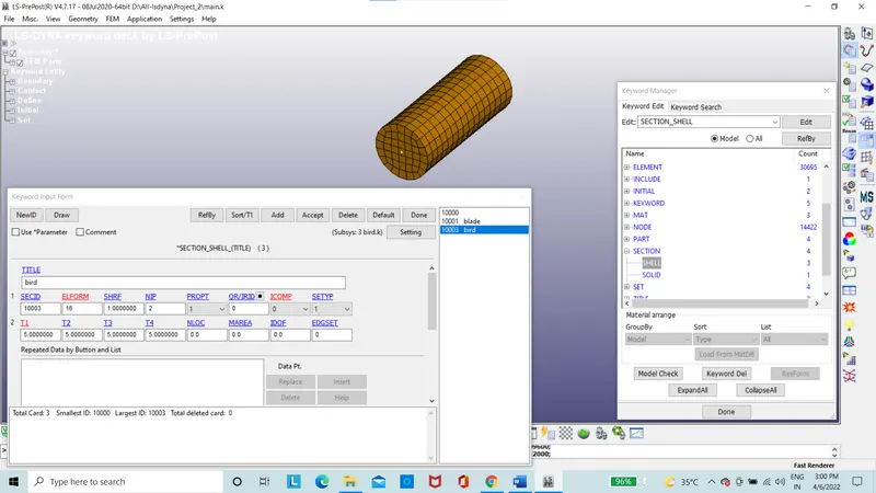
Figure 13: Bird model section
The bird is assigned with elastic material model.
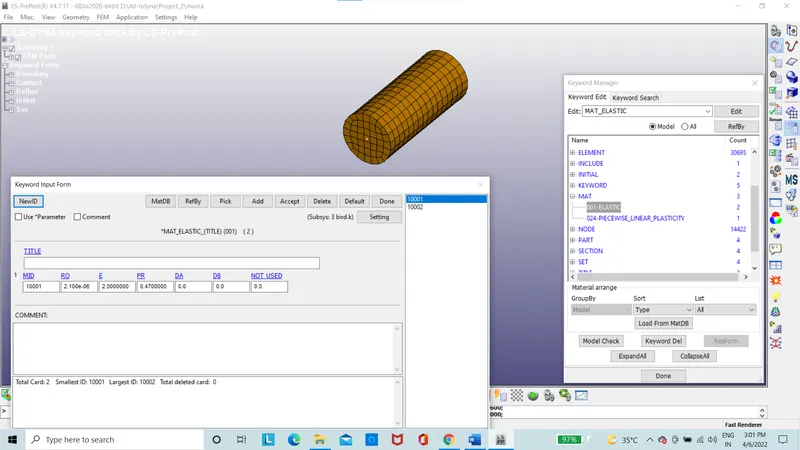
Figure 14: Bird model material
After the section and material properties are assigned.
Then with the include option the separated file are brought in together with main.k file is made.
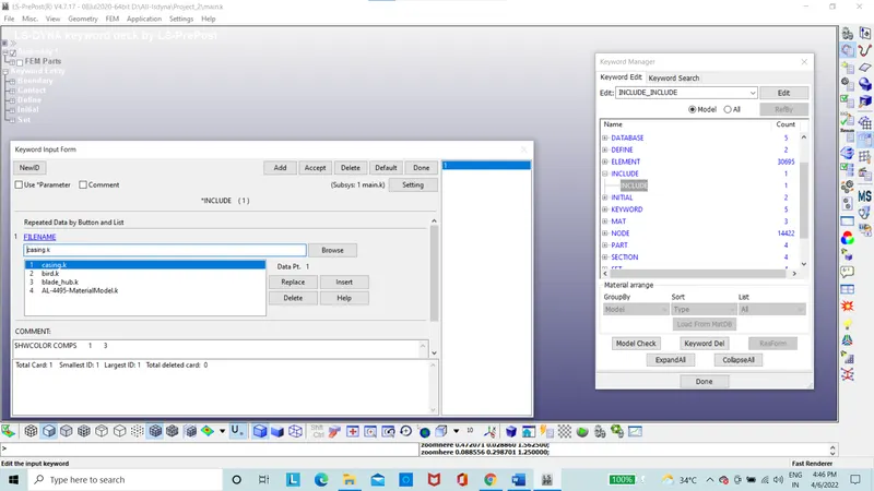
Figure 15: Include option of main file
The main file is reopened with all the parts
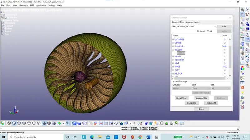
Figure 15.1: Main file with all parts
The boundary condition is set with SPC when the bird model hits the blade there will be motion. Therefore, the blade is constrained along the X-direction.
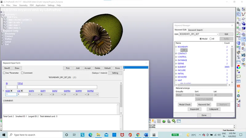
Figure 15.2: SPC boundary condition
Contact condition is established between the blade as salve segment and bird as master segment with automatic surface to surface contact.
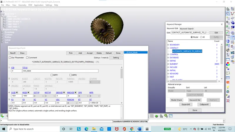
Figure 16: Automatic surface to surface contact
Velocity generation card is used to rotate the blades.
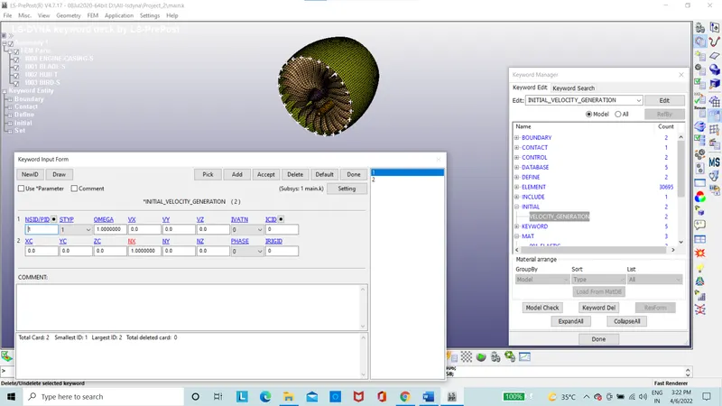
Figure 17: Velocity on blades
Velocity generation card is used for bird to hit the blades.
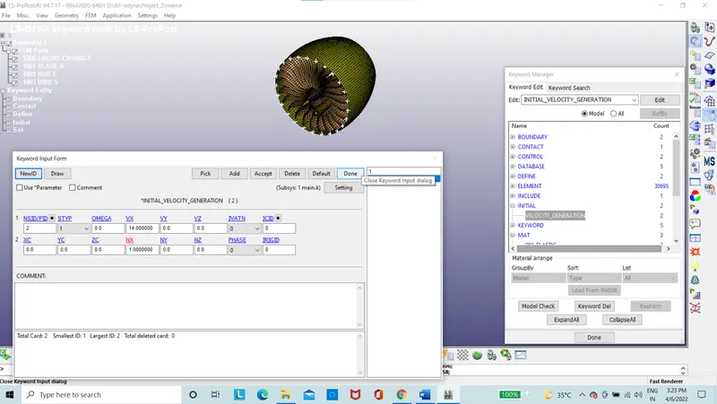
Figure 18: Velocity on bird
Timestep curve is defined.
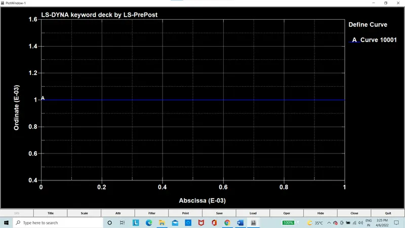
Figure 19: Timestep curve
Timestep card is used in the control option.
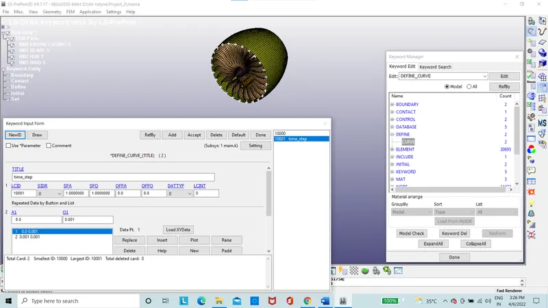
Figure 20: Timestep card
Termination card is used to set the time.
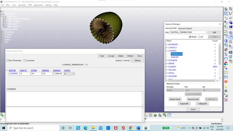
Figure 21: Termination card
ASCII key card is used to get the results.
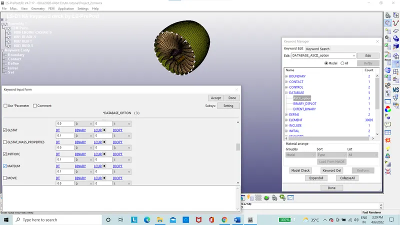
Figure 22: ASCII option
D3POLT is used for DT= 0.1.
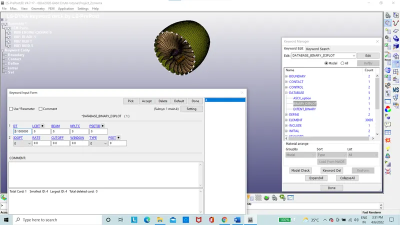
Figure 23: D3PLOT card
Extent binary card strflg is set to 1 for plastic strain results.
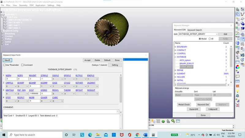
Figure 24: Extent Binary card
The file is saved and run.
The renumbering of the nodes is done at +100000, elements at +500000, parts at 1000 and all other Keywords are between 10000-19999.
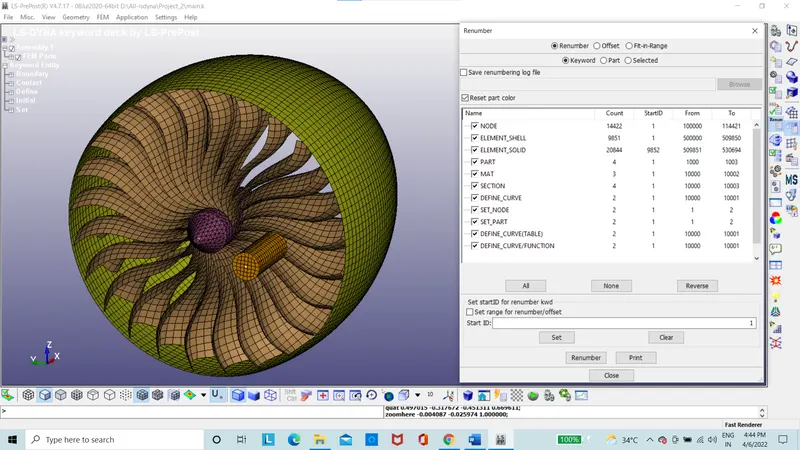
Figure 25: Renumbering ID
The mass scaling of the system is done by giving DT2MS=-9.5e-6 with TSSFAC as 0.9
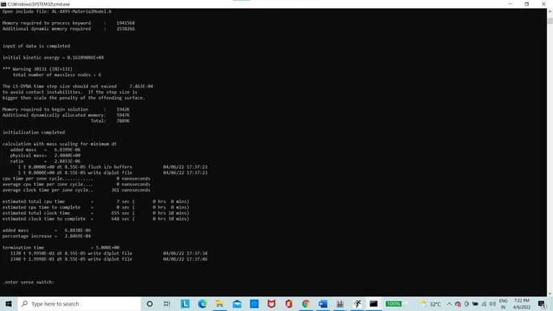
Figure26: DT2MS mass scaling
The mass scaling of the system is done by giving DT2MS=-1.5e-6 with TSSFAC as 0.9
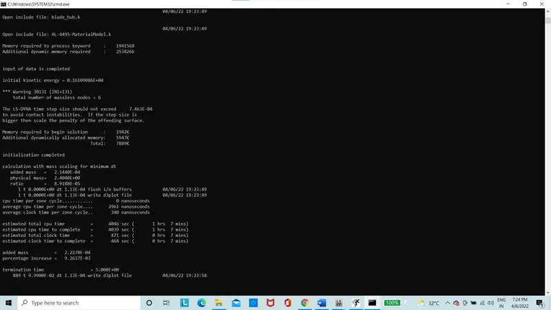
Figure27: DT2MS mass scaling
The mass scaling of the system is done by giving DT2MS=-3.5e-6 with TSSFAC as 0.9
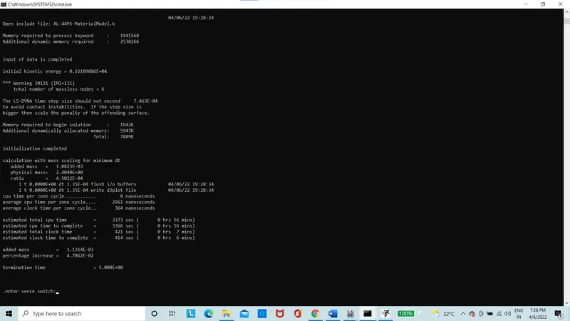
Figure28: DT2MS mass scaling
The mass scaling is done only till 8% for stability reasons and with the mass scaling the time of simulation executed was reduced to 3 mins 58 sec from 20 mins
Results:
The bird strikes the aero engine on the blades and the results are obtained therefore on the blades without DT2MS.
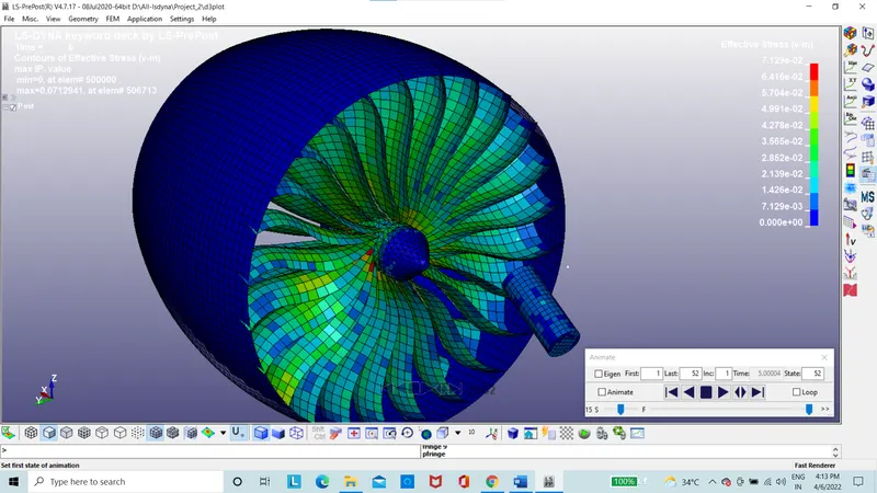
Figure 29: Von-mises stress of Blade
The von-mises stress of the blade is 0.071 Mpa.
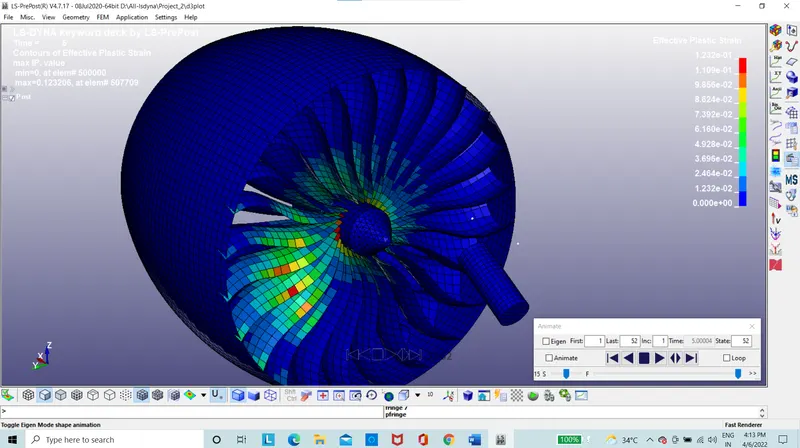
Figure 30: Effective plastic strain
The effective plastic strain of the blade is 0.1232 strain.
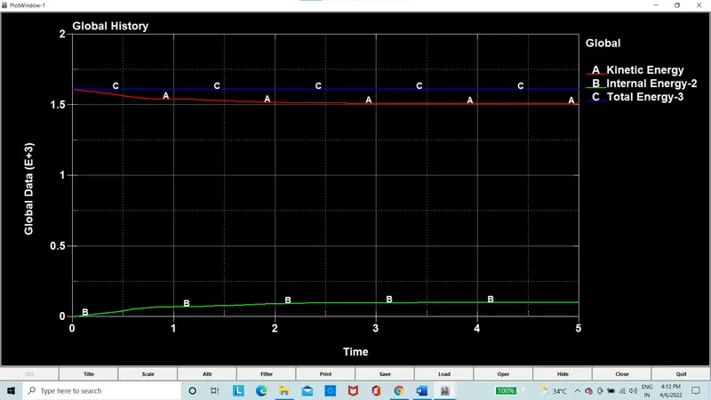
Figure 31: Total energy of the system
The total energy produced by the system, when the bird strikes the blades there will be a drop in the kinetic energy that is show in the graph.
The bird strikes the aero engine on the blades and the results are obtained therefore on the blades with DT2MS.
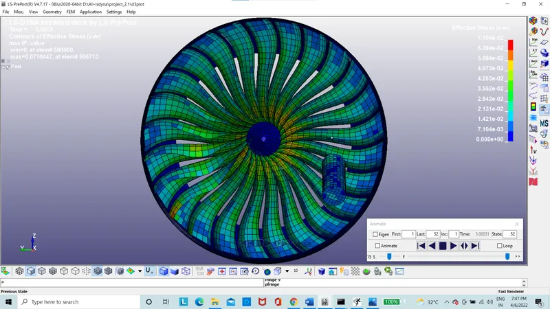
Figure 29: Von-mises stress of Blade
The von-mises stress of the blade is 0.071 Mpa.
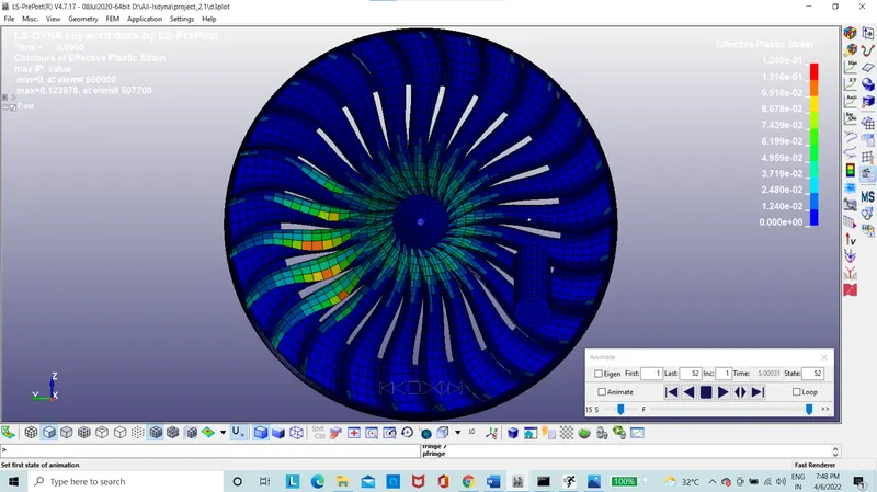
Figure 30: Effective plastic strain
The effective plastic strain of the blade is 0.124 strain.
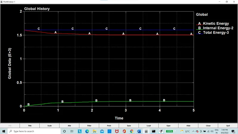
Figure 31: Total energy of the system
The total energy produced by the system, when the bird strikes the blades there will be a drop in the kinetic energy that is show in the graph.
Conclusion:
The simulation of the bird strike is done and the results of stress and strain are observed, the mass scaling is done, the include option is used in the main file to give reference to import all other parts.
Animation of the bird striking the blade is attached in the google drive.
https://drive.google.com/drive/folders/14WWtdKcIBcGVq58Tm2zymcDVfVwOTqdZ?usp=sharing