Bird Strike - Project - 2
OBJECTIVE
- Simulate a dummy bird strike in aero engine case.
- Use the given material data for different objects. If the data insufficient, use reliable sources to get the missing information.
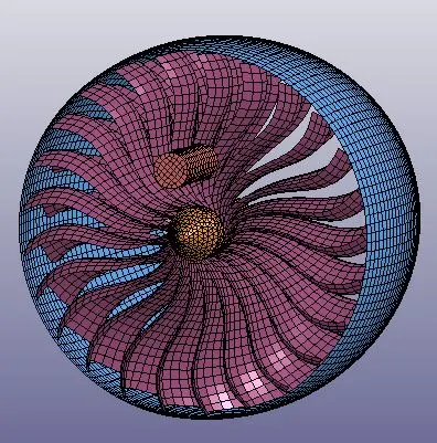
- Approach: Blades moving at constant rotational velocity, casing is fixed and bird is approaching the engine.
- Establish a unique numbering system for different components to be included in keyword file.
- Try mass scaling approach if necessary.
- Make different keyword file for different components and different inputs. Combine each in main file using *include keyword
NOTE
The unit system followed in this activity is kg-mm-ms
THEORY
- Bird strike is a common occurrence in aero engine mainly during the take-off and landing of aircraft and thus its study becomes important to understand the adverse effect on the integrity of structure. Bird strike is highly non-linear and transient simulation case, where various non linearities are involved and it depends on the velocity of both engine as well as bird and also on the angle of impact.
- Ideally such cases are built using advanced techniques like Smooth particle hydrodynamics (SPH), but since our goal is to learn the steps involved and not to get an accurate results, we can use a dummy object as a bird.
- Typical setup used in our study is as follows
PROCEDURE
Following list provides the details of different keywords are used in these activity
- Creating Individual components
- Material, section and Part creation
- Boundary condition
- Contact setup
- Control card and database
- Renumbering technique
- Include
Creating Individual components
- The file provided is the whole assembly consisting of Casing, Blades, Hub and bird. We can save individual components either by deleting the other components and saving it or by creating another subsystem and saving it using subsystem manager.
- By this we create 4 different component file. Casing, Blades, Hub and Bird.
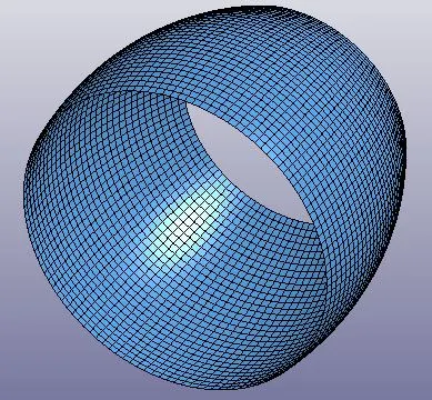
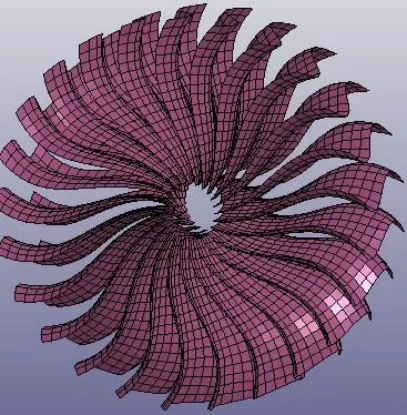
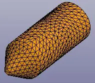
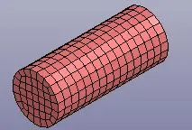
- Now since we will be assigning the contact between these components, It is a good practice to assign the component set as slave and master. Thus partset and nodesets are created for each component.
Material, section and Part creation
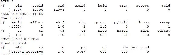
- We have the material properties of blades as elastic plastic aluminium is considered for the study.
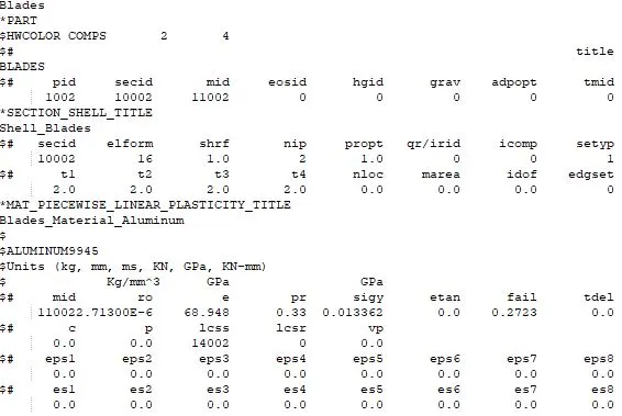
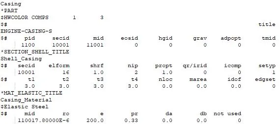
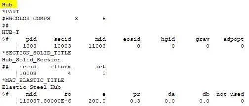
- For bird and casing elastic material is considered with elastic modulus 2GPa and 200 GPa is taken. This means the material for bird is similar to human muscle and the casing is considered as steel. For convenience the material of hub is also taken as steel.
- The section for bird, blades and casing is shell with element formulation 16 and for hub solid element formulation 4 (since for tetrahedron elements only 4, 10 and 13 are applicable).
- Subsequent images shows the details of part, material and section of each component.
Contact setup
- Now we require few contact cards to define the interaction between different components. For this we can use the Surface to surface contact/Node to surface and single surface contacts.
- For blade and bird, automatic surface to surface contact is defined with bird as slave and blades as master.
- Hub and blades are tied together using Tied surface to surface contact with blades as slave and hub as master.
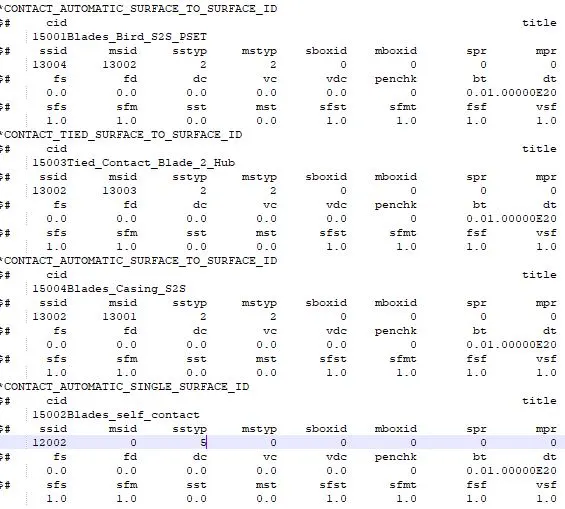
- In actual simulation practice where SPH approach is used, there is no contact between bird and casing and thus following that context, surface to surface contact between bird and casing is not taken into consideration. This can be added if required at later stage with bird as slave and casing as master.
Boundary condition
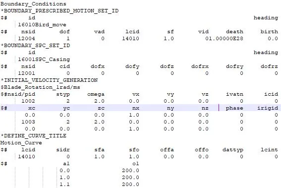
- According to assumption the casing is steady and thus spc is created constraining it in all direction.
- Hub and blades rotate along the same axis with an rotational velocity of 1 rad/ms and this is defined using Initial_velocity_generation. Here different velocities were tried out but due to simpler setup higher rotational velocities like 5, 10 or above seem to cause few instabilities with blades getting detached outwards.
- Now Bird is moving at the speed of 200mm/ms along the direction of its axis and this is defined using Presccribed motion set.
Control card and database
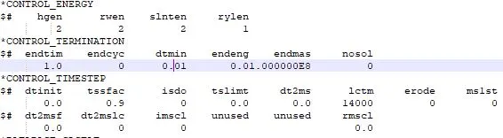
- The different control cards used in our study are Control_Termination, Control_Timestep, Control_Energy. The timestep control card is used for using different timestep and explore mass scaling approach. Control energy card is required to ensure that hourglass and sliding interface energies are captured in our output.
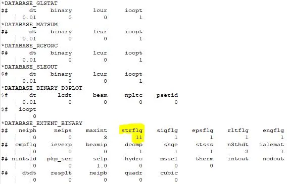
- For database, binary d3plot, asci glstat, matsum, sleout, rwforce are written
- The additional database card of extent_binary is written to capture the strain value correctly.
Renumbering Approach
- Since the main aim of the study is learn the organizing approach along with setting up the simulation, a unique numbering approach has been used here.
- For eg 100000+ for nodes, 500000+ for elements, and 1000+ for the parts. All other keywords should be numbered within 10000-19999 while following a range for each one. The detailed description can be seen in the below figure.
- Although since no of components in our study are very limited, the proper numbering approach helps us identify and rectify the missing or incorrect information when dealing with 100s of component with its unique ids.
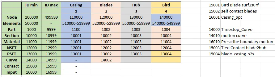
- Here an attempt is made to allocate specific number series to each component eg (1 = casing, 2= blade, 3=hub and 4=bird). So any part, section or material etc involves that digit at the end of the id no. Eg. Material in Casing = 11001, blades = 11002 etc.
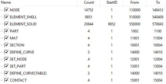
- The list below gives a cummulative details of numbering structure
Include
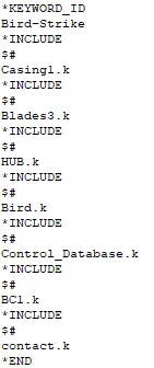
- We have created different files for each component and also we defined contact, boundary conditions and database cards separately. Until now these files individually have no significance. But now we have to create a single file to merge the created files and run a successful simulation.
- For this *Include is used. A separate main.dyn file is created and all the keyword files are called using *Include keyword.
- This practice is followed almost universally in all industry where different material, section configuration are used for different component and they are compiled in single file to formulate a working model of the assembly.
RESULTS
After compiling all the files, simulation is run. Following data has been extracted from the result files
- Energy Plots
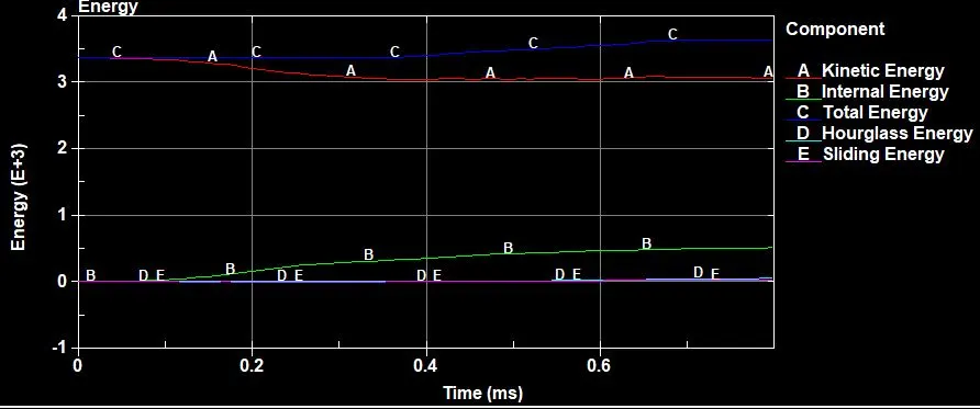
From the above image, we can save that total energy is almost conserved. Also hourglass energy is very less signifying there is no significant element distortion.
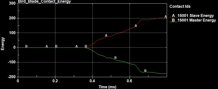
The images represents the sliding energy between bird and blades upon contact
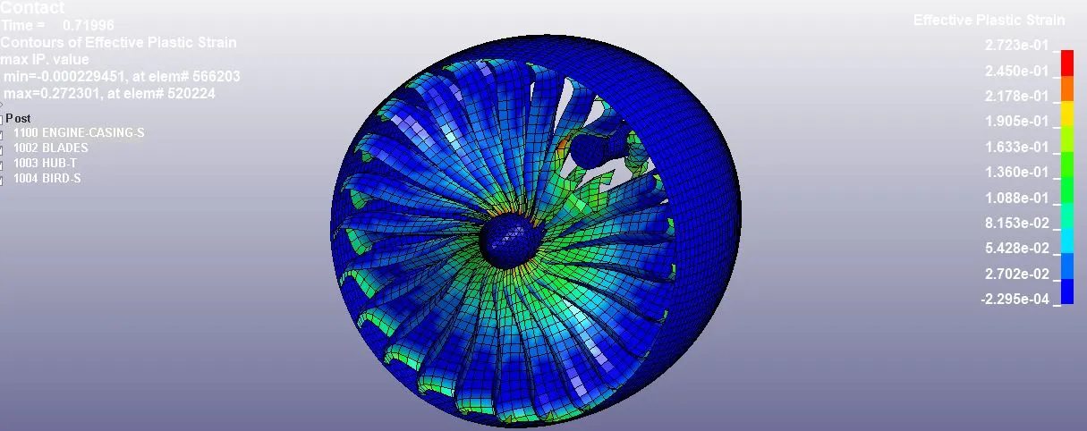
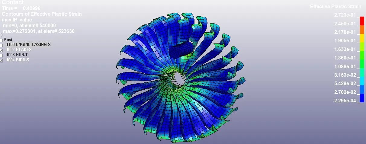
- Stress Strain data Whole


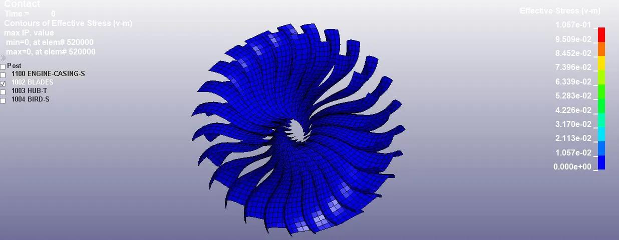
- Stress strain data blades

MASS SCALING
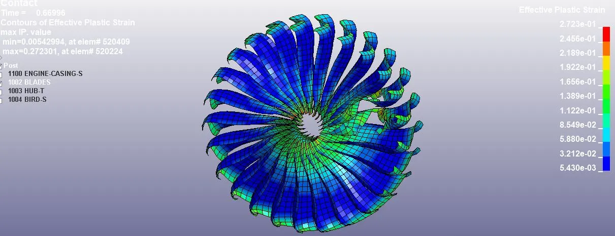
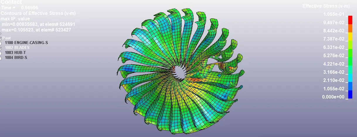
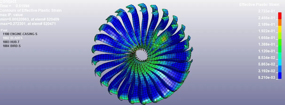
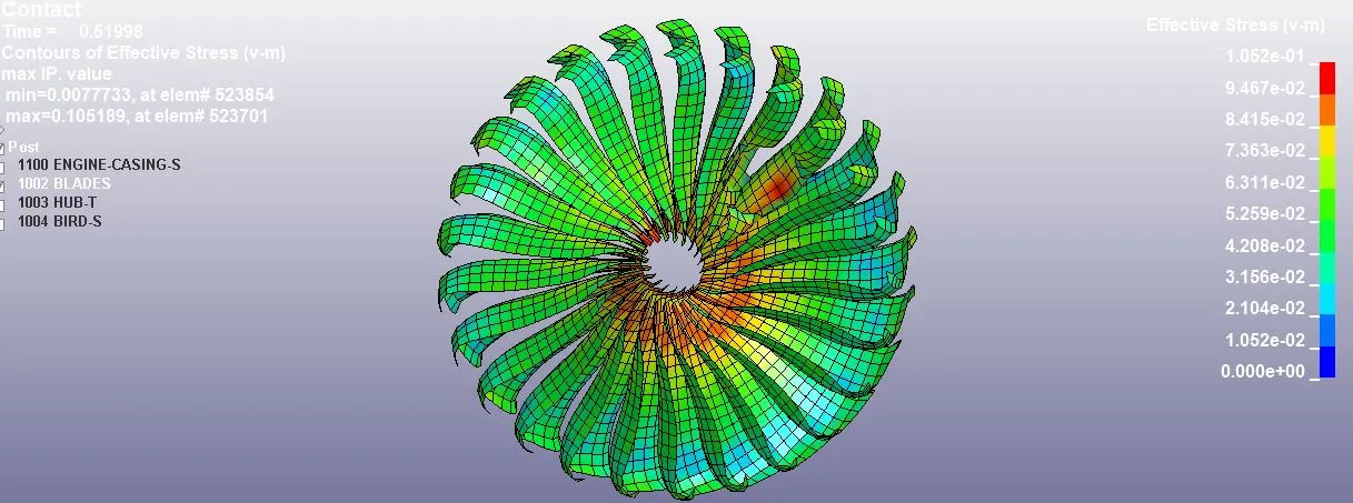
- Often in complex cases like this mass scaling approach is explored to ensure the quick result to the problem. Here we have tried 2 different mass scaling instances and the results are as follows. The TSSFAC is 0.9 for all cases. The stress strain data on the blade is captured to check for the stability of the simulation. It shows that strain in all the cases is same whereas there is minute variation in stress in GPa (i.e 4th decimal place)
|
|
DT2MS |
Physical Mass (kg) |
Added Mass (kg) |
Mass increase % |
Simulation Time (sec) |
Stress on blades (GPa) |
Strain on blades |
|
Original |
0 |
1.4780 |
0 |
0 |
627 |
0.1057 |
0.2723 |
|
Mass scaling 1 |
-2e-4 |
1.4780 |
0.0572 |
3.87 |
229 |
0.1055 |
0.2723 |
|
Mass scaling 2 |
-2.3e-4 |
1.4780 |
0.1267 |
8.57 |
191 |
0.1052 |
0.2723 |
Mass scaleing 1
Mass Scaling 2
CONCLUSION
The above activity helpe us understand the procedure as to how to setup a complex problem like bird strike having components in each different keyword file using include keyword. Also mass sccaling is explored to understand how it affects the simulation and stress strain data is captured in all cases to ensure stability