Bird Strike - Project - 2
Project 2: Bird Strike
Aim
The primary objective of this project is to simulate and analyse the dynamic effects of a bird strike on an aero engine blade using nonlinear transient dynamics principles. It entails accurately modelling the interaction between the rotating blades, the stationary casing, and the bird model under high-velocity conditions to predict blade failure within a brief period. The study will utilise explicit solver techniques to ensure precise results, adhering to structured numerical and file organisation methodologies.
Objective
- Simulate the impact between a bird and rotating engine blades using an explicit solver.
- Maintain a constant rotational velocity for the blades while keeping the casing stationary.
- Ensure the bird model travels along its axis and strikes the blades correctly.
- Assign elastic material properties (Bird: 2000 MPa, Casing: 200 GPa).
- Set velocities to induce blade failure within a brief period.
- Follow a structured numbering system (Nodes: 100000+, Elements: 500000+, Parts: 1000+).
- Number other keywords within the 10000-19999 range while maintaining consistency.
- Separate the bird, casing, and blade components into distinct input files.
- Create a main input file referencing all other files for an organised simulation.
- Define control cards and boundary conditions in a separate dedicated file.
- Ensure reference paths allow flexible relocation without breaking file connections.
- Include an input file, simulation animation, and a report in the final submission.
- Log debugging challenges and solutions in the report for documentation.
- Explicitly describe the numbering approach in the report.
- Conduct mass scaling trials and document effects and optimisations.
- Utilise a provided meshed file with essential components.
- Develop a dummy model for efficient debugging before running a full-scale simulation.
Procedure
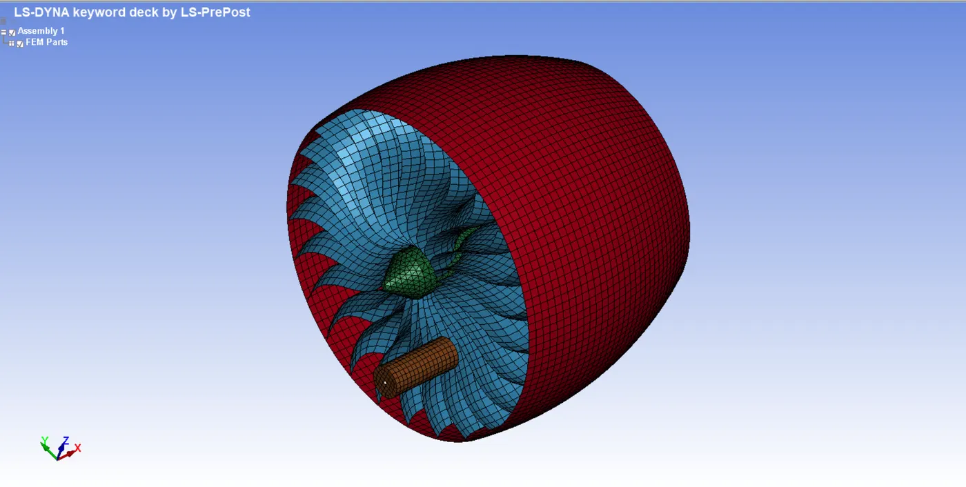
Step 01: Separating geometries into distinct keyword files and performing renumbering.
The parent keyword file includes four individual geometries.
- Engine Casing
- Blade
- Hub
- Bird
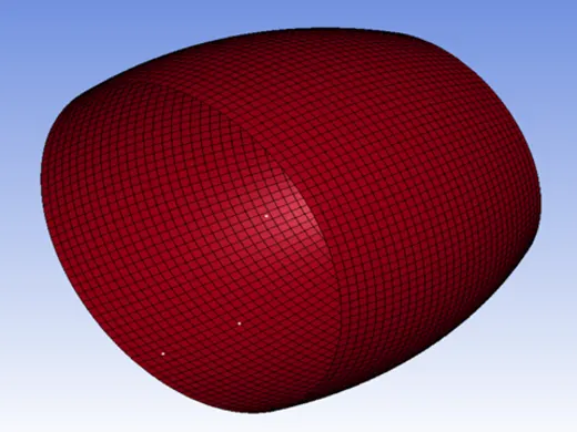
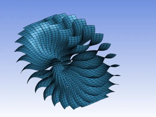
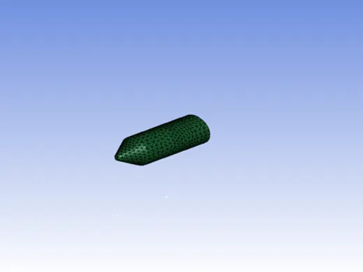
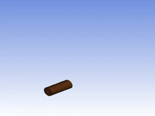
Our main goal is to divide these geometries into four separate keyword files and renumber the nodes, elements, and parts according to the numbering system specified in the objective. First, select the 'Engine Casing' and remove all other remaining parts from the file. Then, proceed to renumber the nodes, elements, and parts sequentially.
For Nodes
- Model and part >> Renumber >> Keyword >> Select Node >> Start ID =100001 >> Set >> Renumber
Untick the 'reset part colour' option to keep the part colour as previously.
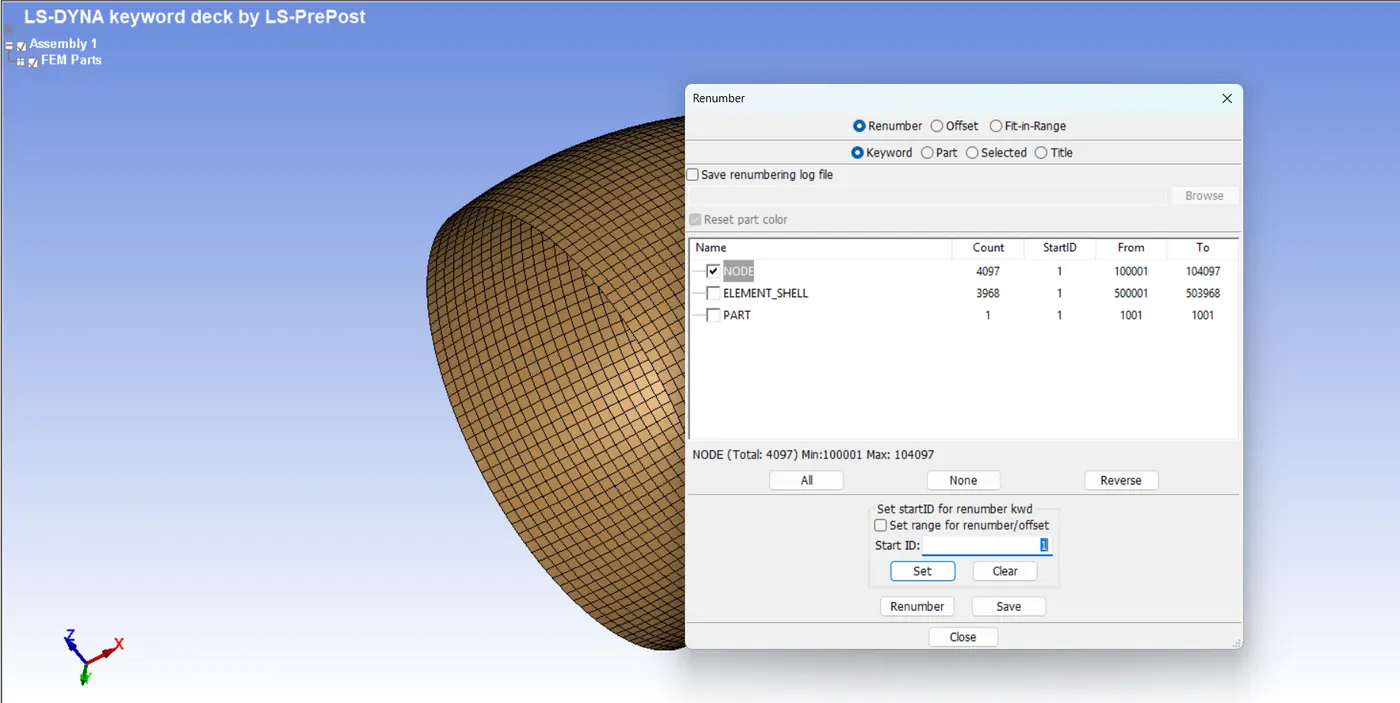
Similarly, for the elements
- Model and part >> Renumber >> Keyword >> Select Elements >> Start ID =500001 >> Set >> Renumber
Foor Parts
- Model and part >> Renumber >> Keyword >> Select Part >> Start ID =1001 >> Set >> Renumber
Save the file with a suitable name. Then, repeat the procedure for every other part and save the keyword file separately in the same folder. The numbering system used for each part is listed below.

Step 02: Defining Sections and Material Cards for Each Models
The project file contains another keyword file named 'AL-4495-MaterialModel.k '. Open this in a new prepost window. The model includes only a MAT024 material card and curve, which are further used to define the material section.
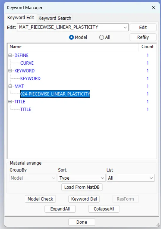
The subsequent step involves defining the material and section cards for each geometry.
We begin with the engine casing. The MAT 001 material card is defined based on the following parameters.
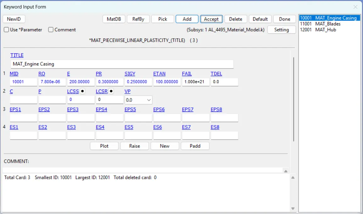
We can use the material card MAT 024 given in the file for the blades. The material card is defined along with a curve.
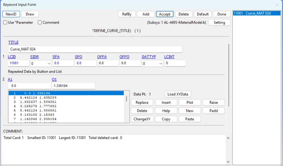
The MAT 024 material card is defined based on the following parameters.
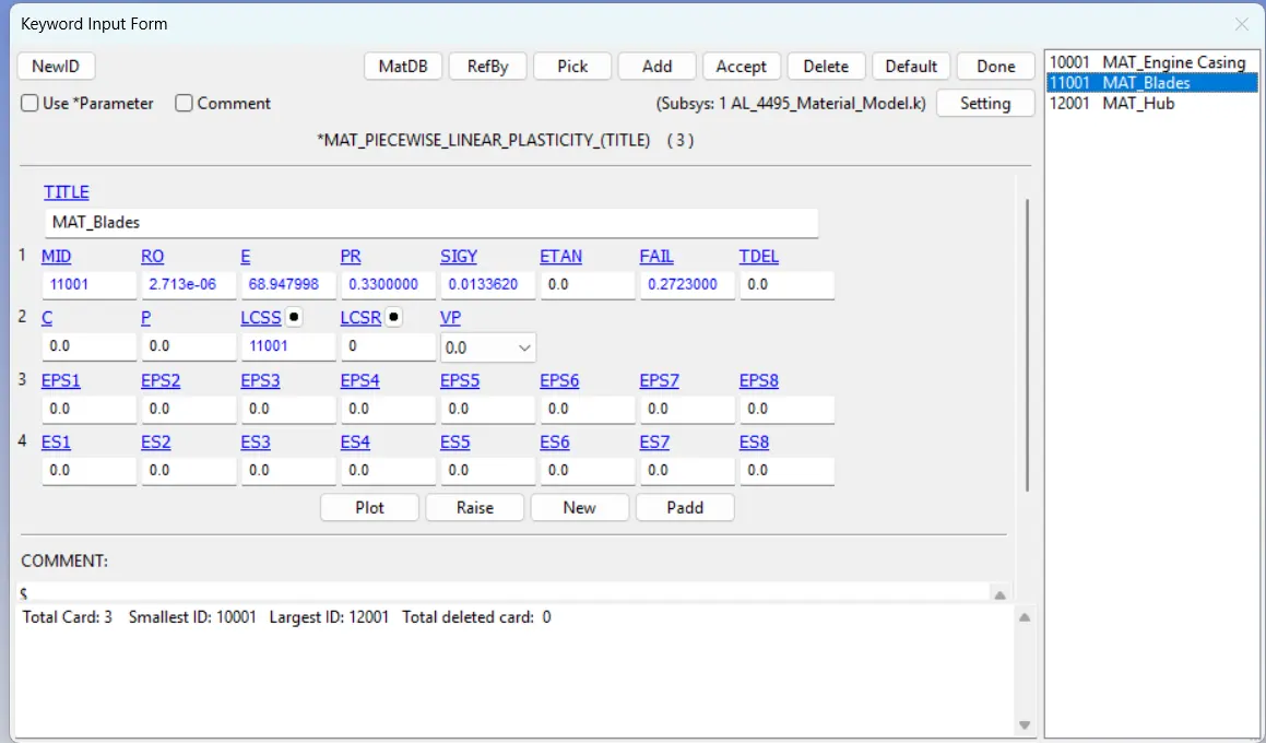
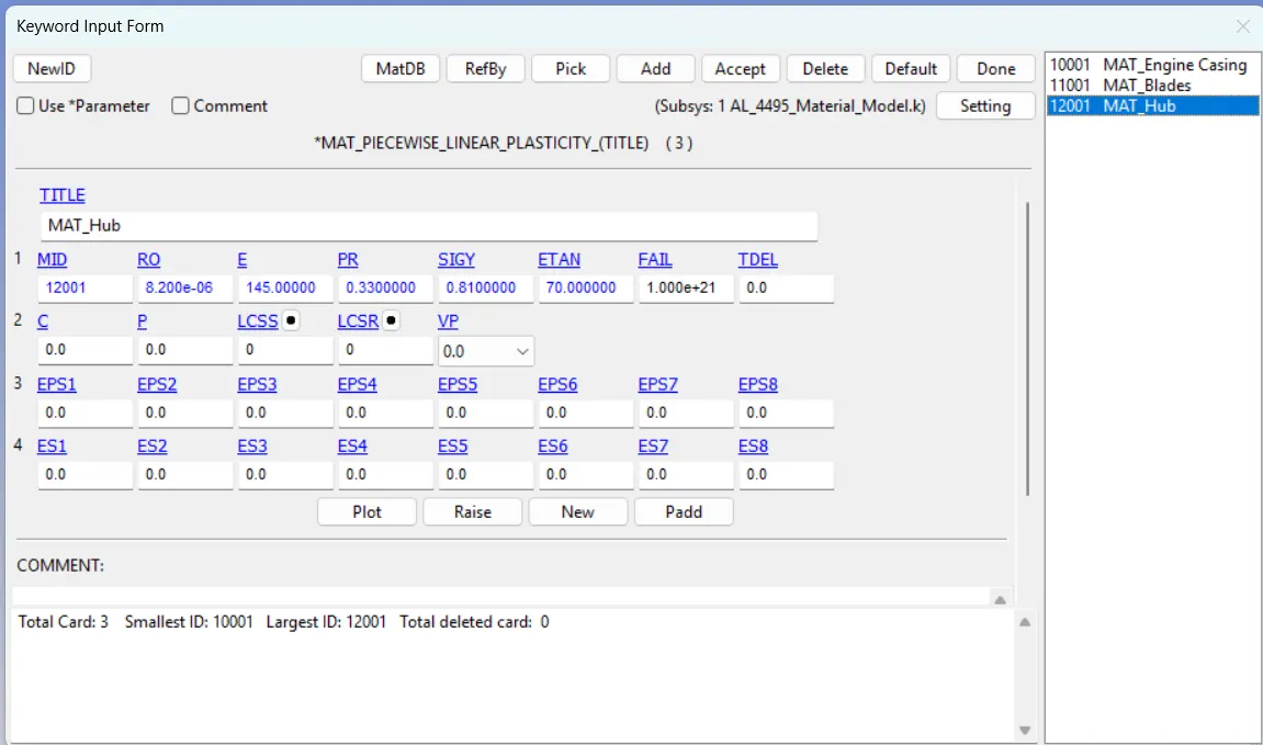
For the hub, we use the MAT 024 material card with different material properties (Steel).
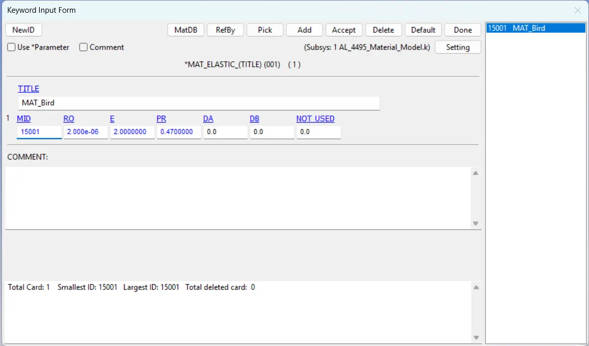
For bird geometry, we use a MAT 001 material card as specified in the objective.
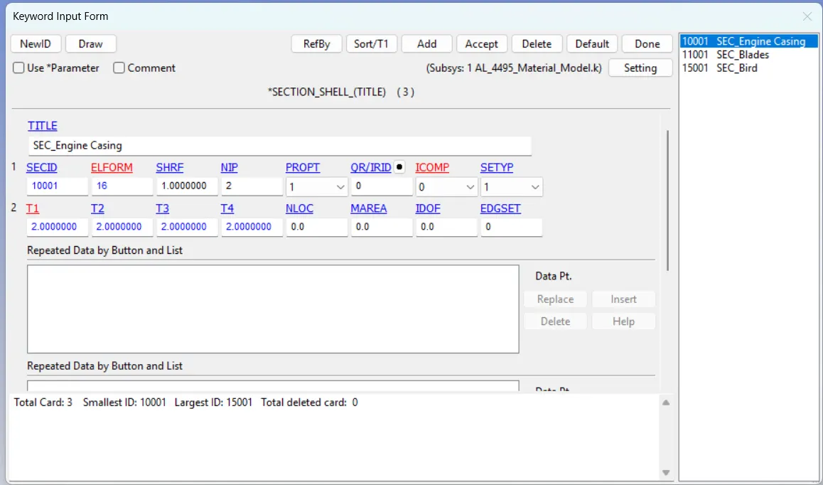
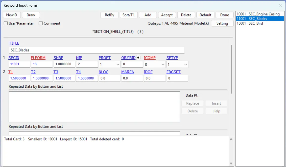
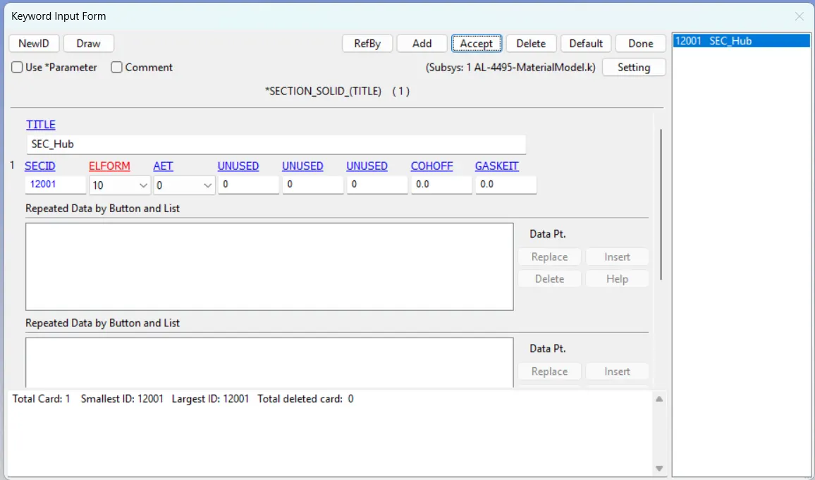
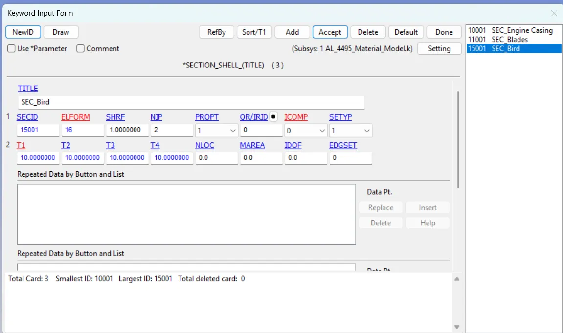
Similarly, the sections should be defined with suitable element formulations and thickness.
For the engine casing, we use the SECTION_SHELL card with ELFORM 16
For the blades, we use the SECTION_SHELL card with ELFORM 16
For the hub, we use the SECTION_SOLID card with ELFORM 10
For the birds, we use the SECTION_SHELL card with ELFORM 16
Save it with a suitable name in the folder where the other keyword file is located.
Step 03: Combining Models and Assigning Sections and Material Cards for Each Part
The next objective is to merge all five keyword files into a single keyword file. It can be accomplished using the INCLUDE keyword.
- Model and part >> Keyword Manager >> All >> INCLUDE >> INCLUDE >> Browse all five-keyword files one by one >> Insert >> Save >> Done.

Save the file with a suitable name. Reopen the file in a new prepost window.
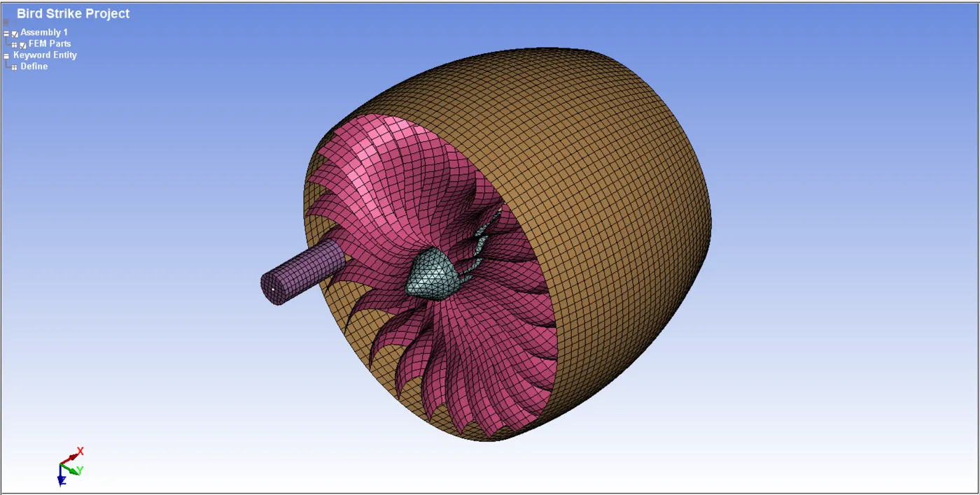
Then, we must assign every material and section card to the respective geometries.
Step 04: Defining Control Cards, Boundary Conditions and Databases
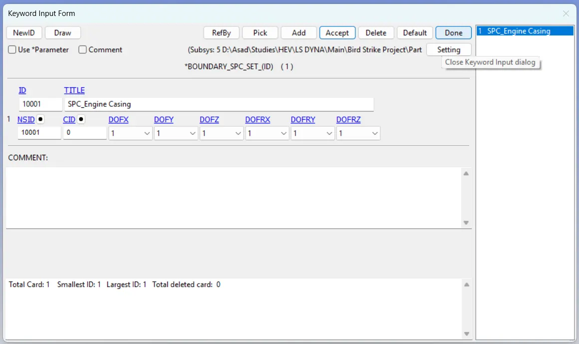
First, we need to constrain all the DOFS of the Engine casing. For that, create a node set that contains all nodes of the engine casing part. Then, constrain all the directions using the BOUNDARY_SPC_SET card.
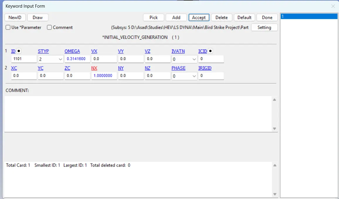
Similarly, the blades have an angular motion. Usually, a jet blade rotates at 2200-4400 rpm. If a value of 3000 rpm is converted to rad/ms, it becomes 0.31416 rad/ms (1 rpm = 0.10472 rad/s). Create a node set that contains the nodes of the blade geometry.
Then, a VELOCITY_GENERATION card will be defined for assigning the angular motion of 0.31416 rad/ms in the x direction.
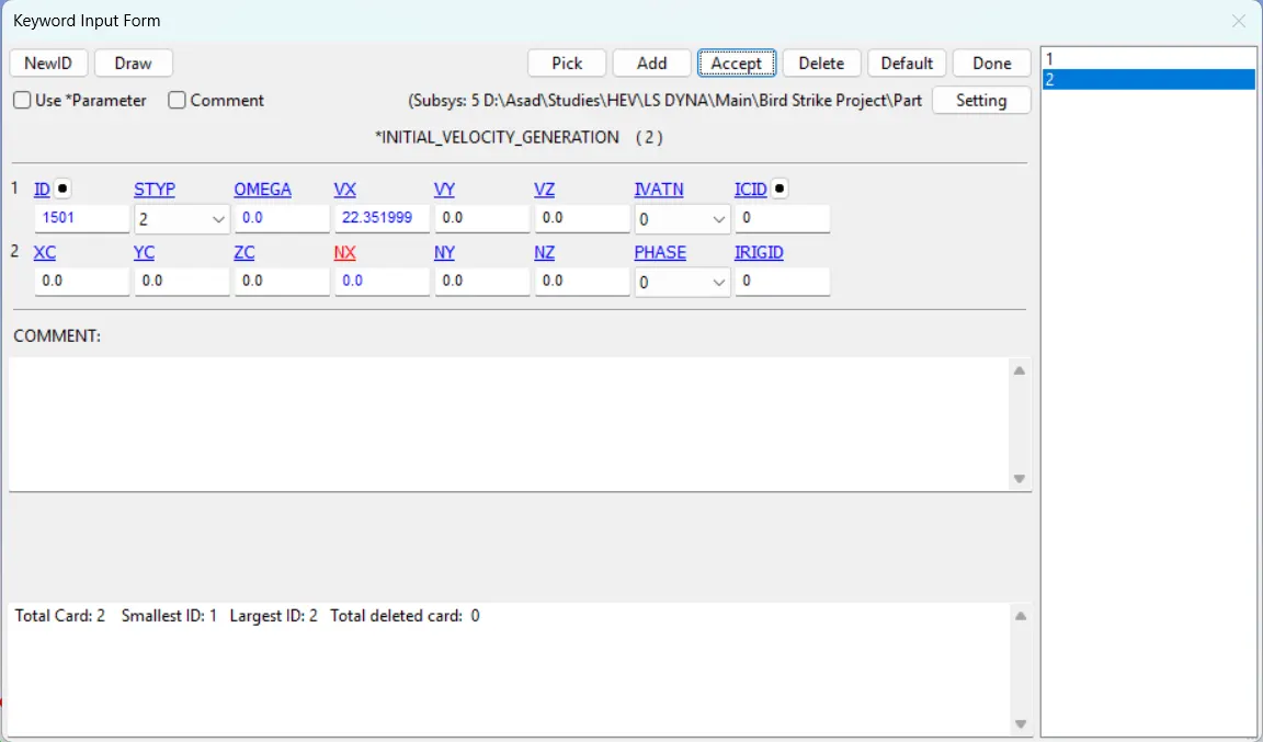
The average speed of a bird is assumed to be fifty miles per hour, which, when converted to millimetres per millisecond, equals 22.352 mm/ms. Create a node set that contains the nodes of the bird geometry.
Then, a VELOCITY_GENERATION card will be defined for assigning the linear motion of 22.352 in the x direction.
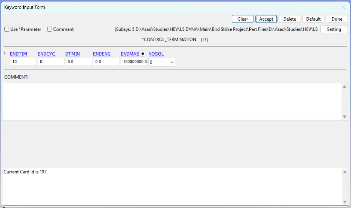
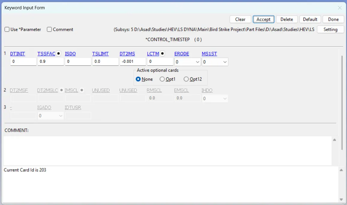
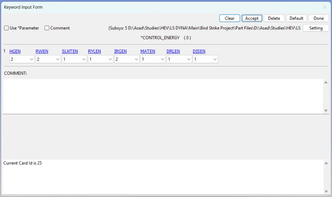
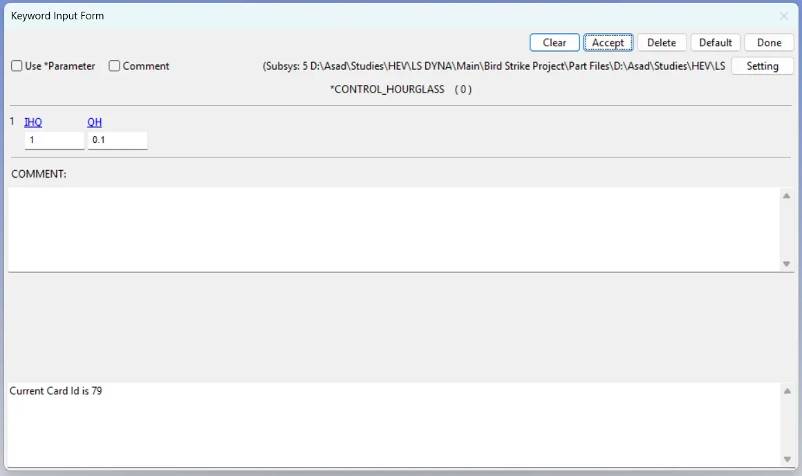
Then, the following control cards are defined in the model.
1. CONTROL_TERMINATION
2. CONTROL_TIMESTEP
3. CONTROL_ENERGY
4. CONTROL_HOURGLASS
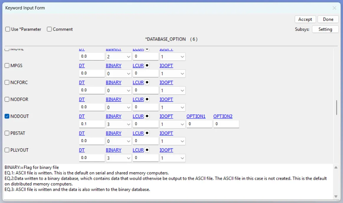
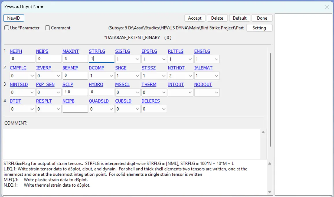
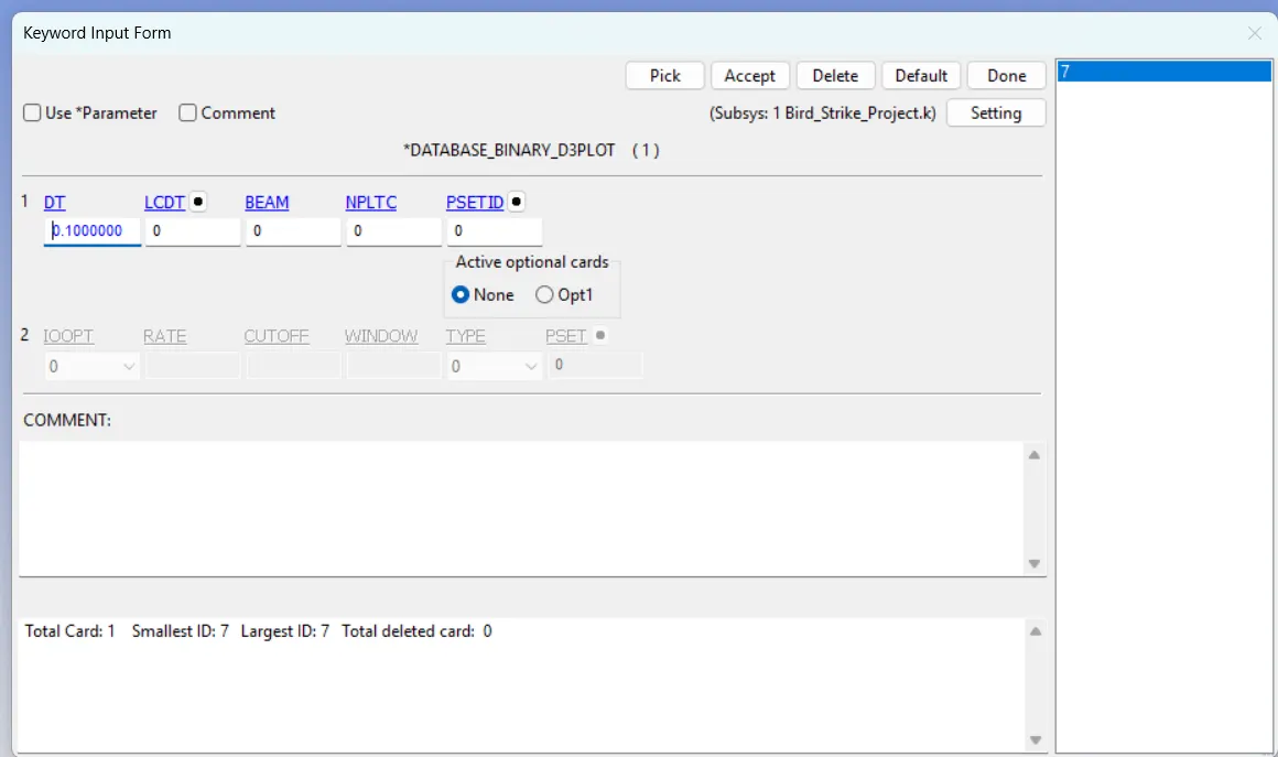
Then, the database cards need to be defined as listed below.
1. ASCII database cards
2. EXTEND_BINARY
3. DATABASE_BINARY_PLOT
Ensure the file is saved with an appropriate name and designated location.
Step 05: Defining Contacts
Open the current file in a new prepost window. Now it's time to define the contacts.
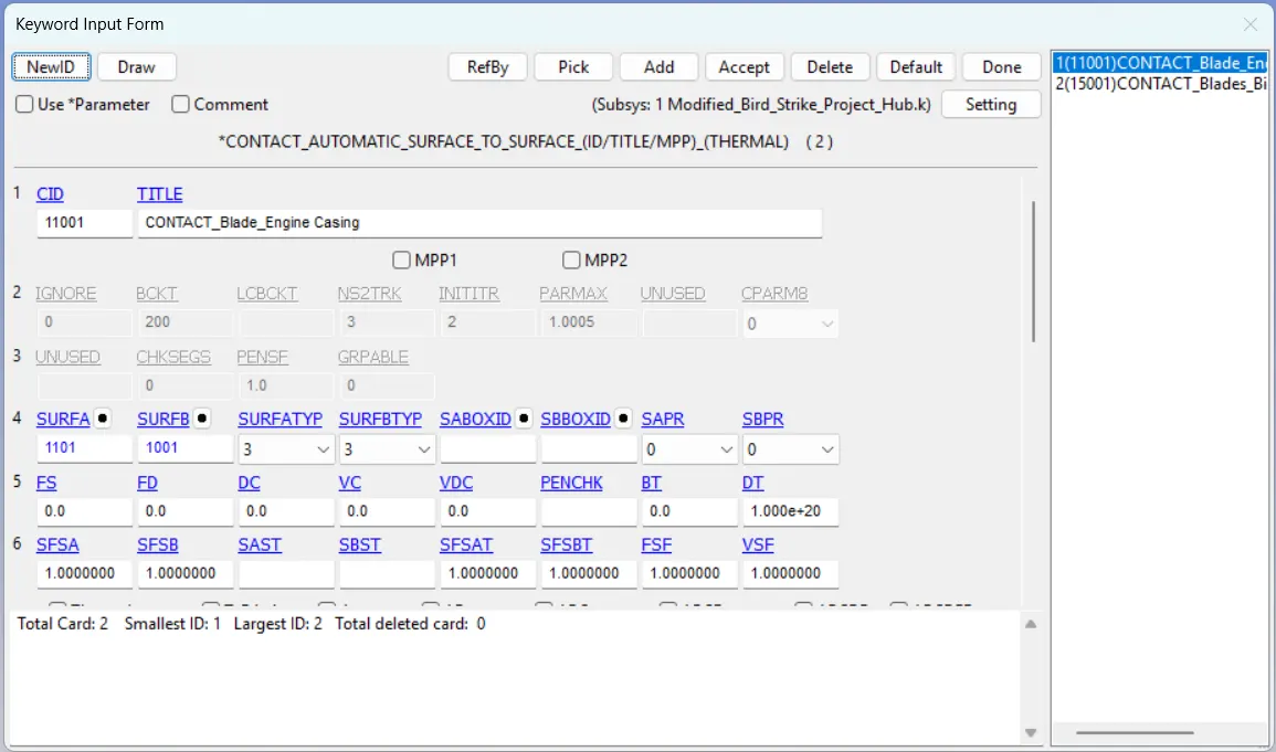
1. Contact between the blades and the engine casing.
AUTOMATIC_SURFACE_TO_SURFACE contact card should be established between the blades and the engine casing, with the blade designated as the slave part and the engine casing as the master part.
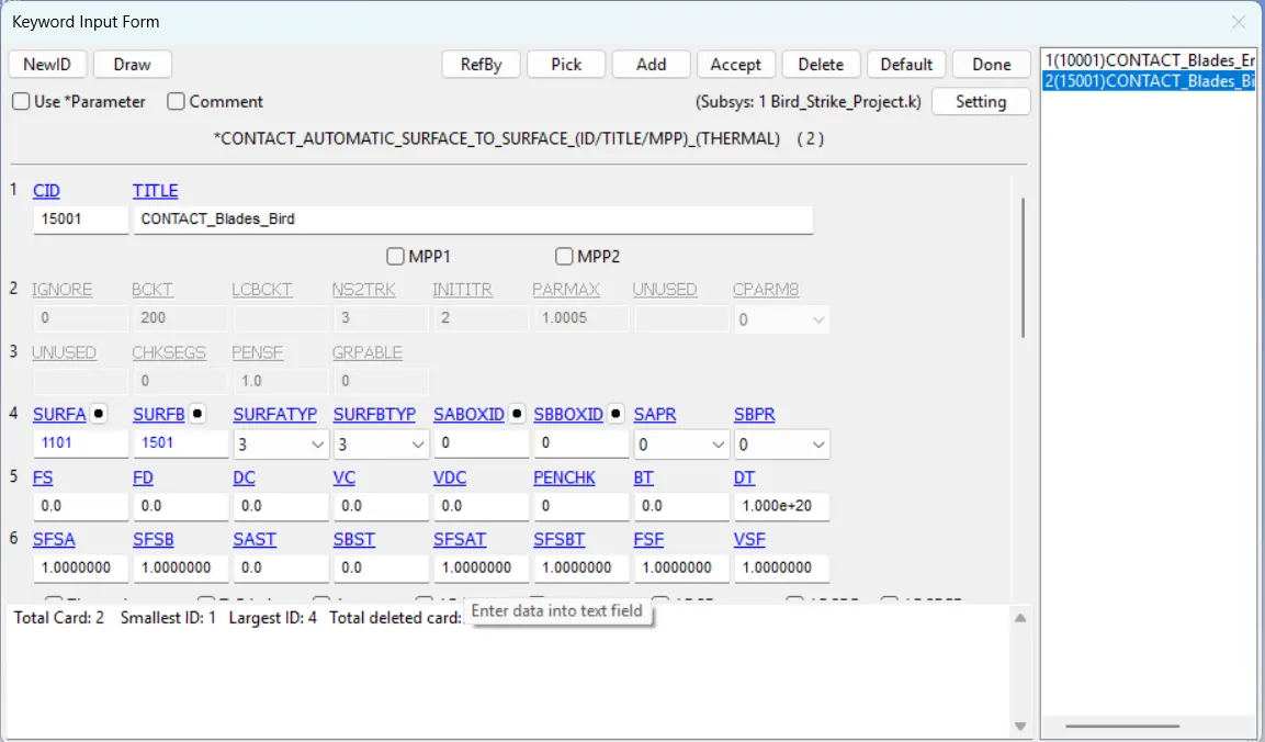
2. Contact between the blades and the engine casing.
AUTOMATIC_SURFACE_TO_SURFACE contact card should be established between the blades and the bird, with the blade designated as the slave part and the bird as the master part.
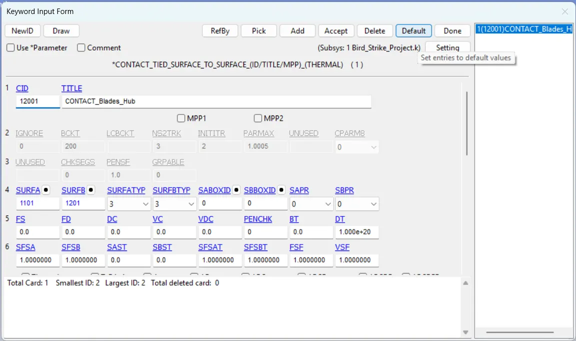
3. Contact between the blades and the hub.
TIED_SURFACE_TO_SURFACE contact card should be established between the blades and the bird, with the blade designated as the slave part and the hub as the master part.
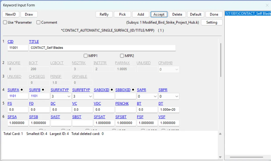
4. Self-Contact in Blades
Self-contact is defined within the blade geometry. The AUTOMATIC_SINGLE_SURFACE contact card should be implemented for the blades, with the blade assigned as both the slave and master part.
Step 06: Model Checking and Simulation
Once the case design is finished, it's important to ensure the model is free of major errors. This can be done by reviewing and refining the model through keyword checking. Then save the file and run the simulation.
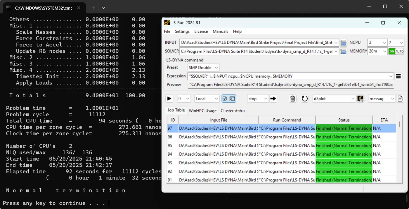
The above is the final simulation.
There are some errors which is popped during the trial runs of the simulation, such as
- The value of DT in DATABASE_BINARY_PLOT is incorrect.
- There are errors in defining contacts when selecting slave and master parts.
Results
1. Animation
OneDrive link for the animation file: https://1drv.ms/v/c/7380bfd26cab3f61/EcllshA7RhZAi0Dgh3IPGfUB7luJfaB5ct4nU9BkWvZgpA?e=R96CCo
2. Von Mises Stress
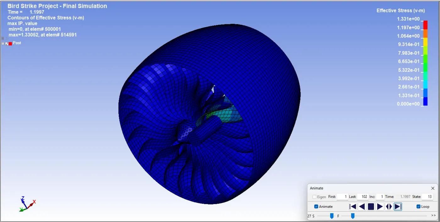
The impact of the bird on the blade caused a deformation in the blade. The blade experiences a maximum VM stress of 1.33052 GPa at 1.1997 ms on element 514591. The element is positioned at the point of contact between the hub and the blades.
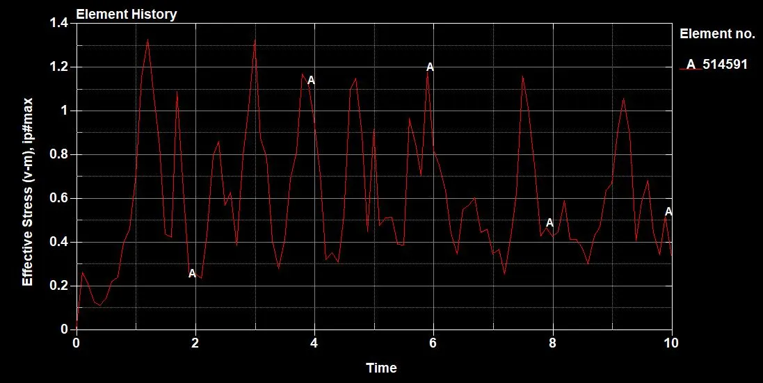
Based on the Element History graph, the effective stress (v-m) fluctuates over time, with multiple peaks marked as "A". This indicates that the material or structural element undergoes different stress conditions even after the impact has occurred.
2. Effective Plastic Strain
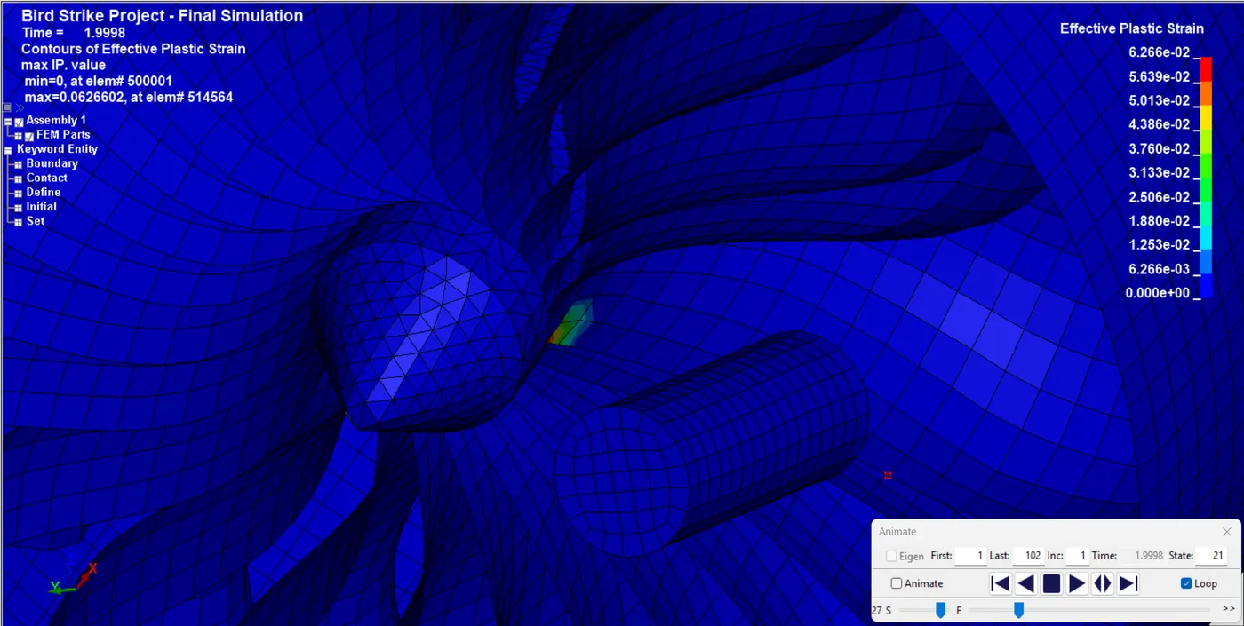
The blade experiences a maximum effective plastic strain of 0.0626606 at 1.1997 ms on element 514591. The element is positioned at the point of contact between the hub and the blades.
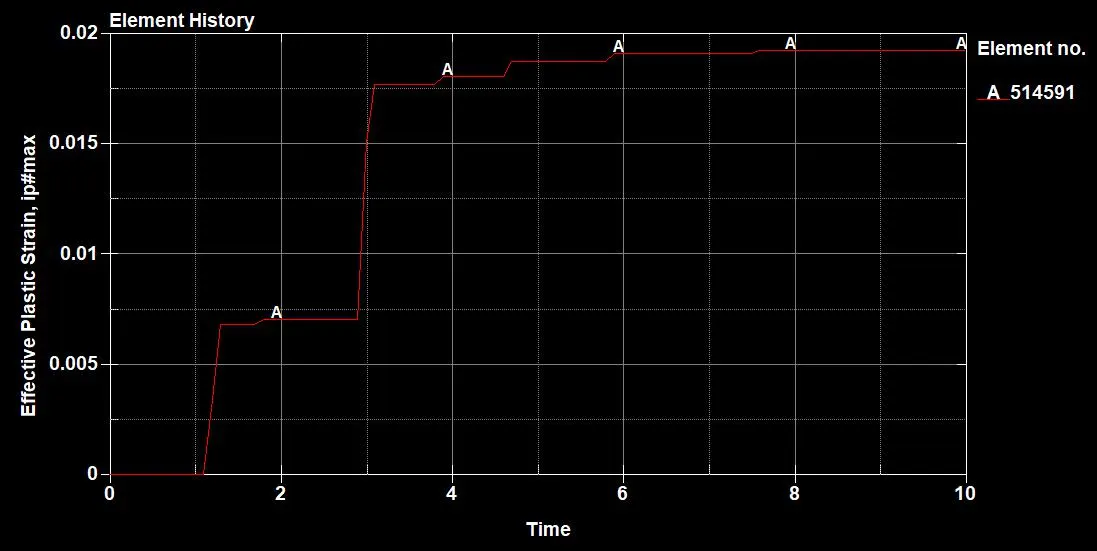
The graph uploaded illustrates the evolution of effective plastic strain for a specific element over time. The red line suggests that strain accumulates in discrete steps rather than in a continuous manner, with marked points indicating significant changes. This graph can inform us about the material behaviour under stress, potentially highlighting when plastic deformation occurs and how strain accumulates over time.
3. Energy Plots
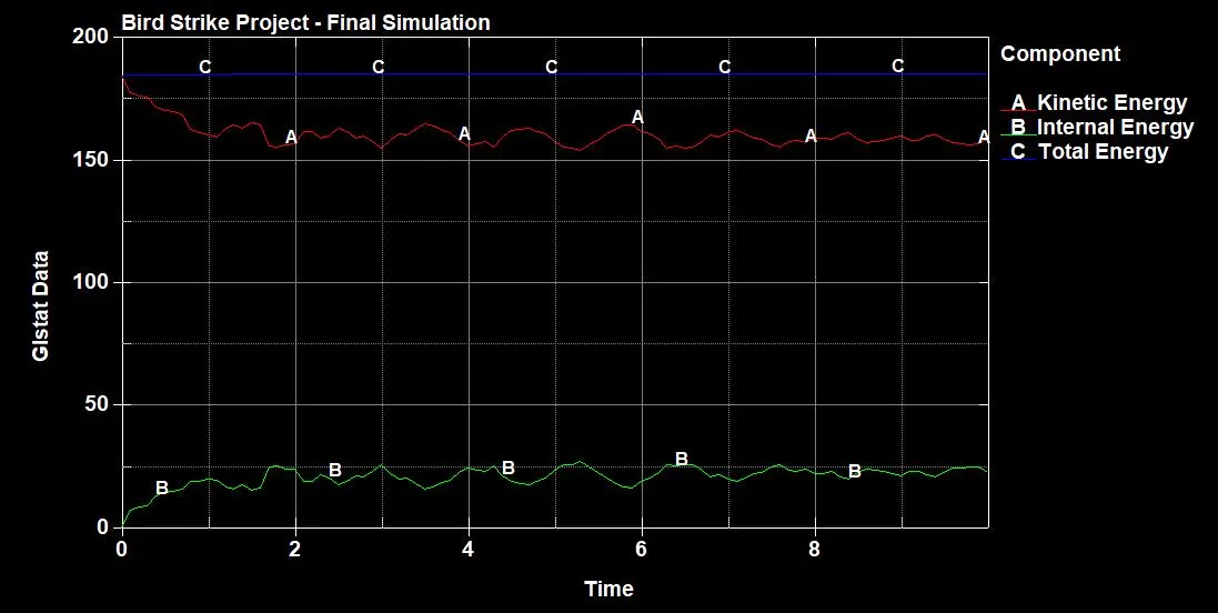
The total energy stays constant throughout the simulation, showing that it ran smoothly. Both kinetic energy and internal energy follow similar trends during the simulation. After the impact, the kinetic energy decreases while the internal energy increases in a similar pattern.
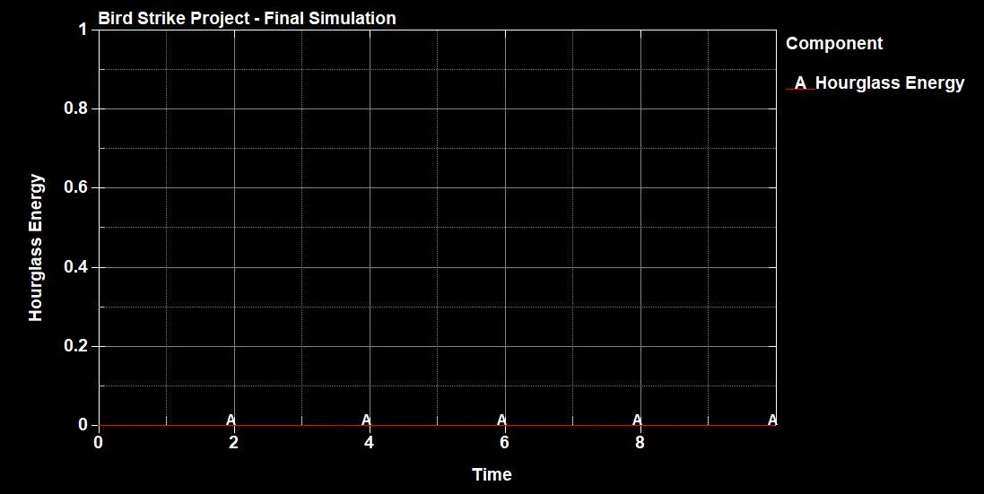
The hourglass energy accumulated during the simulation is almost zero.
4. Contact Energy Plots
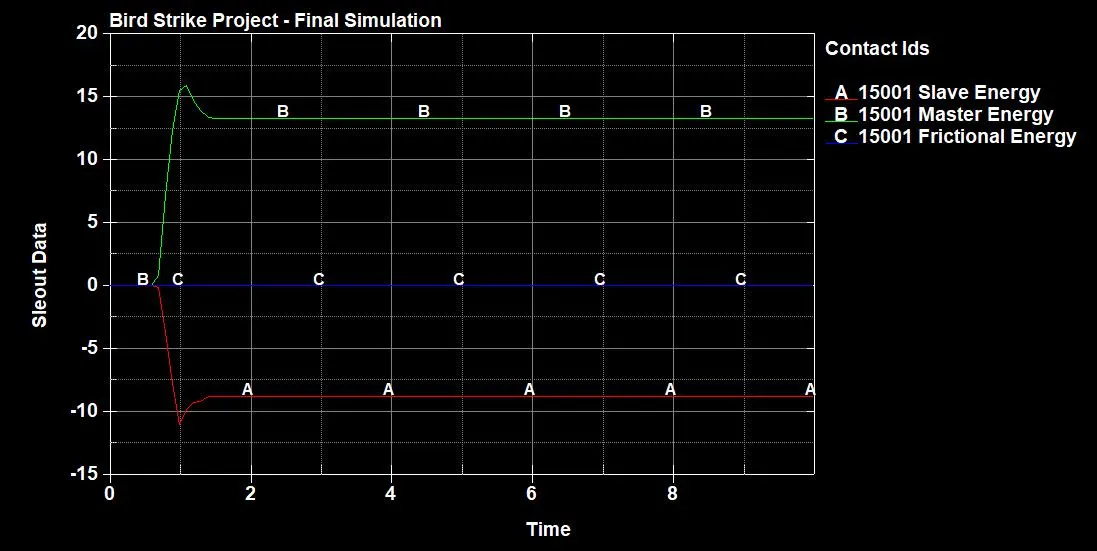
The plot below shows the contact energies accumulated between the bird and the blades.
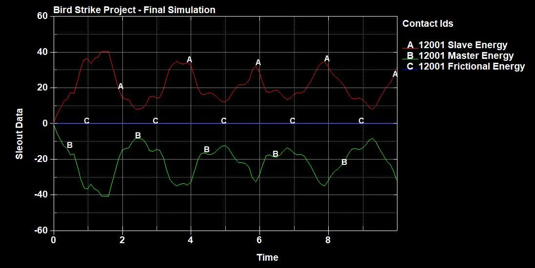
Similarly, the plot below shows the contact energies accumulated between the bird and the hub.
Conclusion
- This simulation successfully captures the high-velocity impact between a bird and rotating engine blades using an explicit solver. By maintaining a structured numerical approach, separating essential components into distinct input files, and ensuring flexible reference paths, the project achieves an organised and scalable methodology.
- Key findings include the effects of velocity adjustments leading to blade failure and the importance of debugging with a simplified dummy model before full-scale execution. The animation and detailed report provide a comprehensive visual and analytical representation of the event, highlighting critical factors affecting blade integrity and structural response.
- Overall, this study offers valuable insights into bird-strike events in aerospace engineering, demonstrating the effectiveness of explicit solvers in predicting real-world impact scenarios.
OneDrive Link for the Project File: https://1drv.ms/f/c/7380bfd26cab3f61/EuquKQeaE9RGvEQFwqrvgA8Bo1chZTk5JxVQAO5MmGH7rg?e=5cARCx