Bird Strike - Project - 2
AIM:
To simulate the non-linear transient birdstrike where, the bird tries to hit the blades of gas turbine by using LS-DYNA.
PROCEDURE:
- Part Creation
- Material and section creation
- Contact creation
- Boundary conditions
- Re-numbering
- Control Cards
- Database Cards
- Model check-up
- Mass scaling
- Post-processing
- Conclusion
Import the Bird strike model:
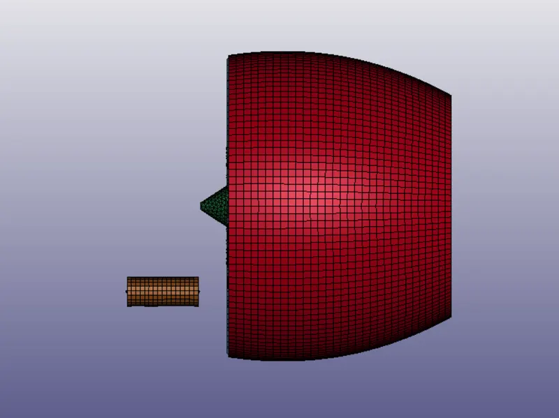
1. Open the bird_strike.k file
We can see there are 4 parts
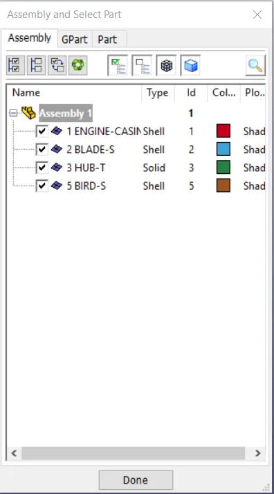
Casing, Hub, Blades, Bird
Isotate one part on GUI and delete the other parts
Save it individually
In my case I have created a part id and node set ID for the same
I have isolated the bird and deleted the other parts.
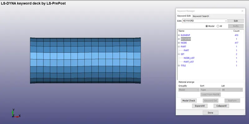
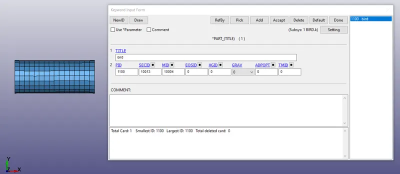
The part set ID and the node set ID for the individual part is created
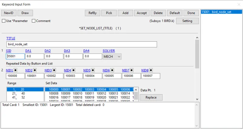
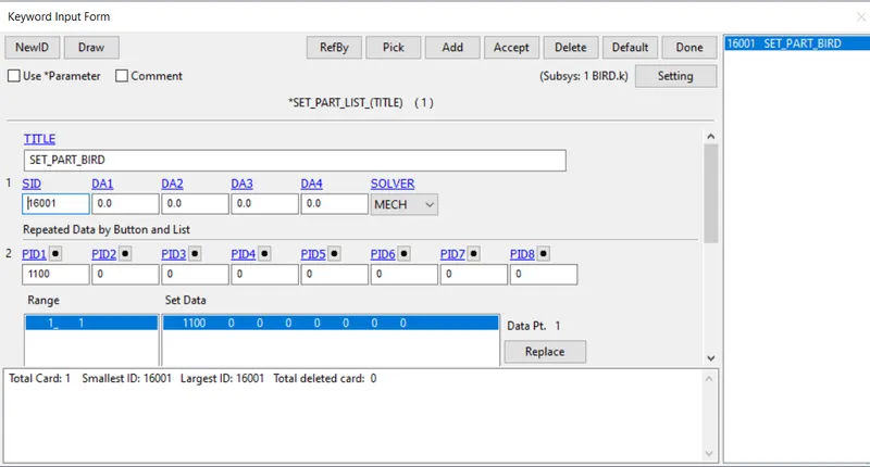
Similarly create the individual part file for all the other three parts

Node set and Part set are created for all other parts:
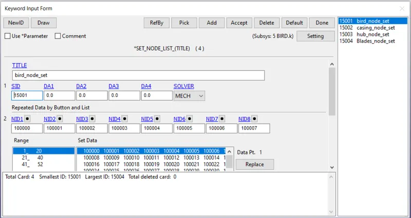
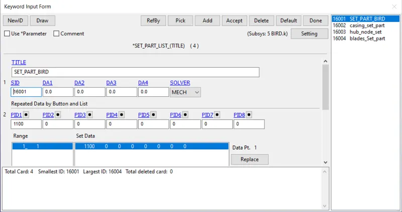
So now we are having 4 parts in 4 different files
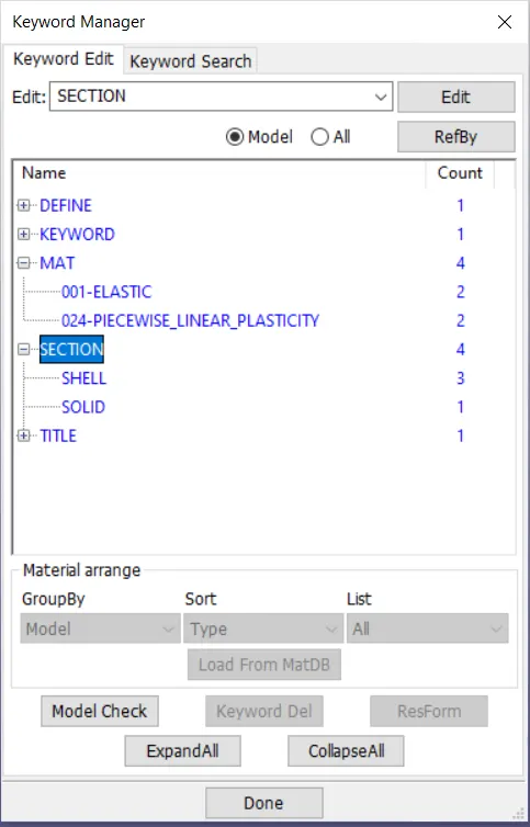
- Material and section creation
The unit system used is kg-mm-ms
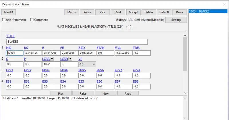
We are provided with the material properties of blades:
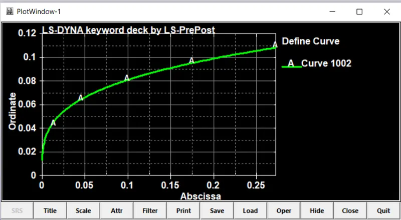
The load curve defined in the material is
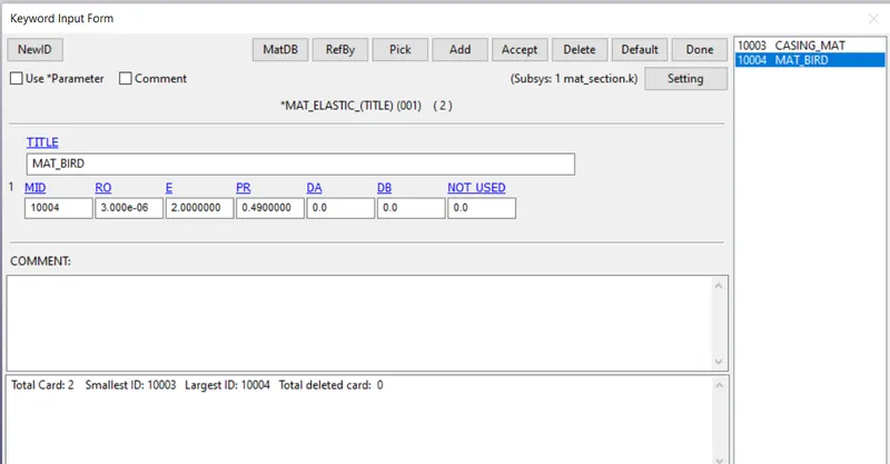
Elastic material is used as Material for bird
From the given data
Young’s modulus = 2 GPa
Density = 3e-6 kg/ mm^3
Poisson’s ratio = 0.49
Density and poisson’s ratio is considered much higher values to see the worst possible scenario of bird impact.
Elastic material is used for casing
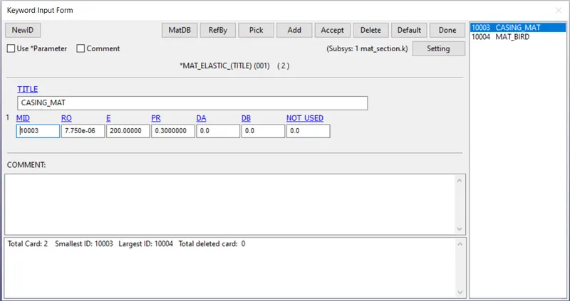
As we know weight place a huge role in building a plane, many of the materials used are composites
We have considered properties of aluminium for the casing
Young’s modulus = 200 GPa
Density = 7.75e-06
Poisson’s ratio = 0.3
Elasto plastic material is used for the hub
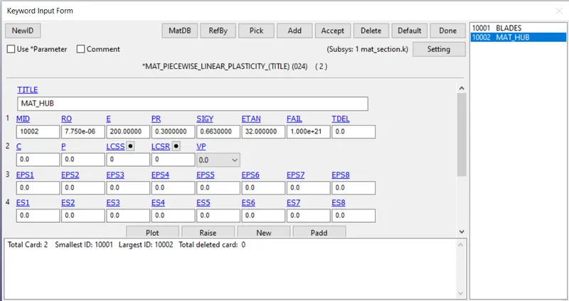
Section creation:
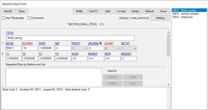
For the bird, blades, casing which are shells
Use section_shell with ELFORM = 16
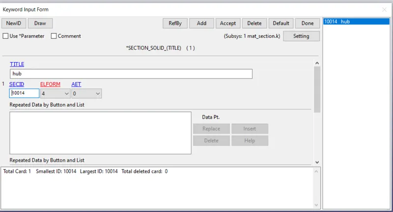
For the hub which is a solid
Use section_solid with ELFORM = 4
2. Contact creation
Contacts created:
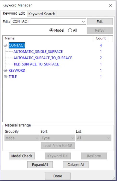
Here we can we there are contacts between the bird and blades during impact
We have created node set ID and part set ID for the individual parts.
For this case in contact card we go for automatic surface to surface contact
We select the bird part as slave and blades as master
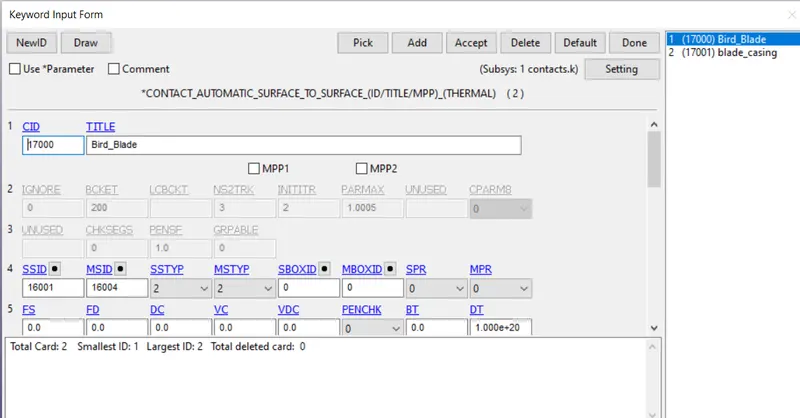
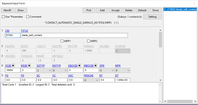
We can see the self contact of blades during impact
Therefore, we have to create a self contact using automatic_single_surface
Select only the blades as slave. We don’t have to define the master as the contact is due to self
We can also define the both slave and master for the blade part to represent the self contact
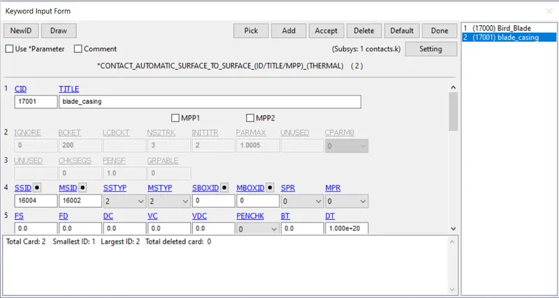
We can also see the contact between casing and the blade part.
For or this case in contact card we go for automatic surface to surface contact.
We select the casing as master surface and blades as slave surface.
We can see there is contact between the hub and the blades
Here hub is the solid part and blade is the shell
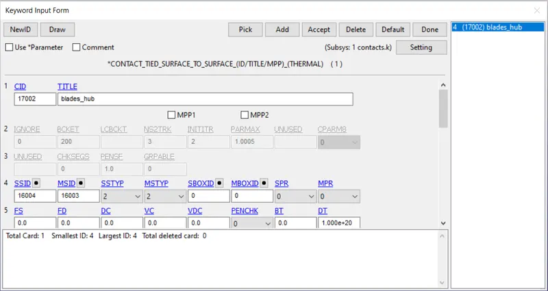
We have to define a tied contact to represent a contact between two surfaces.
Automatic_tied_surface_to_surface contact is used in this case
Select the blades as slave and the hub as the master.
3. Boundary conditions:
Provided boundary conditions:
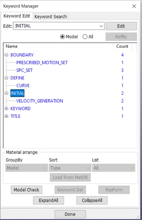
We have to provide the necessary boundary conditions and bring the simulation into natural scenario
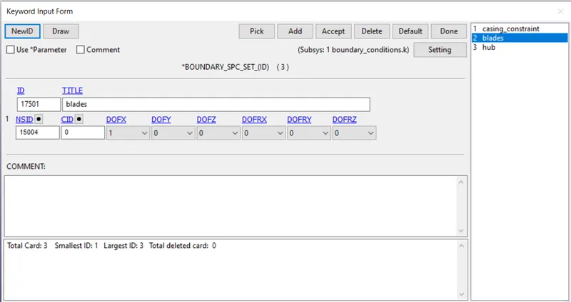
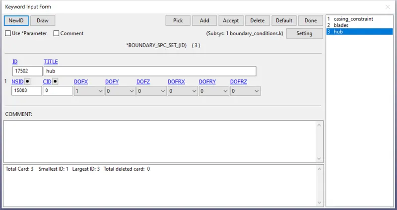
We don’t want the hub and blades to translate in x-direction
The blades and the casing should not be moved in the x-direction during the impact.
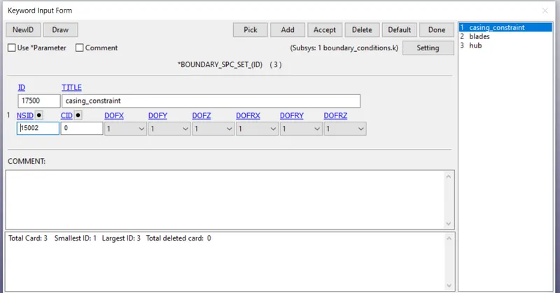
We want the casing to be at the state of rest throughout.
Casing is constrained in all degrees of freedom.
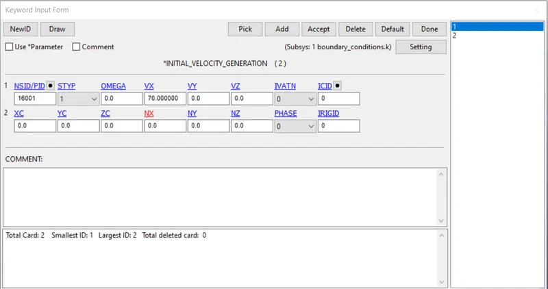
We want the bird to move in positive x-direction with certain velocity.
We have provided the velocity to the bird in x-direction as 70 mm/ms
As the weight of the bird is less, it can travel at a high velocities depending on the bird
We are considering the velocity of bird as 70 mm/ms to see the worst possible case that is due to the impact.
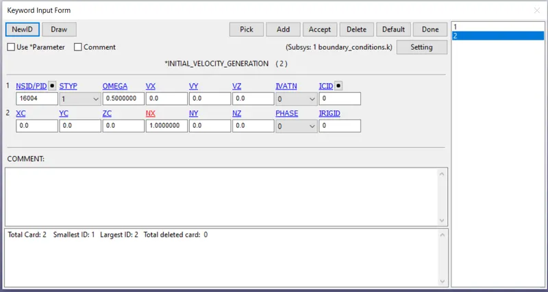
We have to provide the angular velocity to the blades in x-direction
Provide the angular velocity to the both hub and blades.
Select the type of part and enter the pid of the respective.
Provide the value of omega as 0.5 Rad/ms^2 and activate the NX to 1.
NX =1 is representing the direction in which the angular velocity is to be provided.
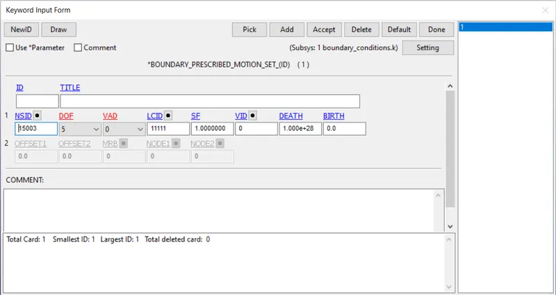
We want the hub to run in a synchronous mode w.r.t the blades.
Go to boundary prescribed motion, and provide the part id of the hub and choose degree of freedom as 5 mm/ms.
VAD =0 representing the velocity
The respective LSID is to be provided
The curve that is defined for the hub to run in synchronously with the blades:
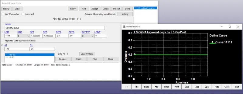
We have defined a curve representing how the velocity is changing over the time
We have defined a curve of constant velocity of 0.5 m/s.
4. Re-numbering
100000+ for nodes
500000+ for elements
1000+ for the parts
All other keywords should be numbered within 10000-19999
I have followed the numbering of nodes, elements and parts from the start of the project
I have considered the given values, when creating a new keyword
Go to model and part >>> re-numbering >>> select the respective part or keyword or node or element and select the part and provide the initial IDs for the consideration.
Ensure the node numbers and element numbers are accordingly.
Keywords and the part IDs should be in according format.
We can see all the nodes, elements, keywords and part IDs are maintained accordingly.
5. Control_cards
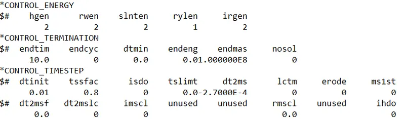
Control_termination:
Control_Termination card is to be provided to specify how much time this simulation has to run.
The run time of the simulation is given as 1ms.
Control_energy:
To consider the Hourglass energy, Sliding energy, Rigid wall energy, we have to activate the respectives in the Control_Energy card.
HGEN: Hourglass energy is computed and included in the energy balance.
RWEN: Rigid wall energy dissipation is computed and included in the energy balance.
SLNTEN: Sliding interface energy is computed and included in the energy balance
6. Database_cards
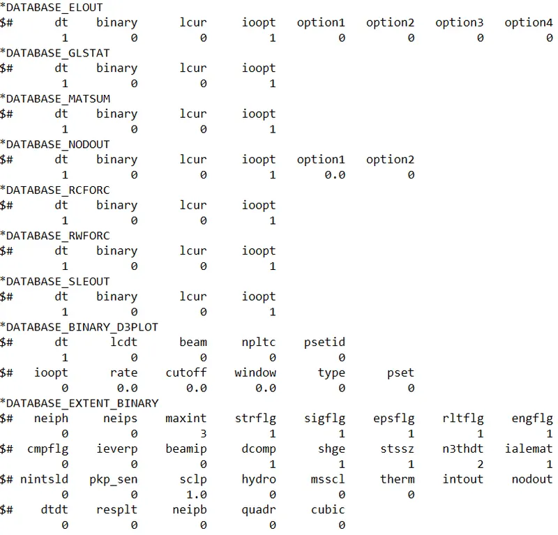
Create the database card:
Request for D3PLOT:
DT = 0.1 :Time interval at which the animation files should be printed.
Database_extent_binary
*DATABASE_EXTENT_BINARY Flag for output of strain tensors.
Writes strain tensor data to d3plot and elout.
For shell and thick shell elements two tensors are written, one at the innermost and one at the outermost integration point. For solid elements a single strain tensor is written.
ASCII
Activate the cards:
GLSTAT: GLOBAL DATA
ELOUT: ELEMENT DATA
MATSUM: NATERIAL ENERGIES
SLEOUT: SLIDING INTERFACE ENERGIES
SECFORC: SECTIONAL FORCES
NODOUT: NODAL POINT DATA
SWFORC: SHEARWALL FORCE
7. Include
Open the new GUI, create include >>> include
Add the all above files to the include file
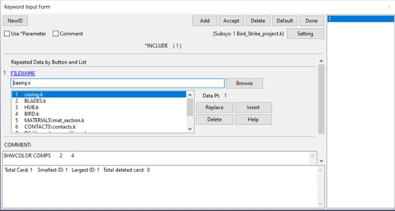
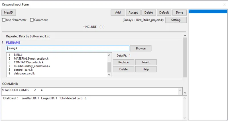
The files added to the include file are
- Casing
- Blades
- Hub
- Bird
- Material and section
- Contact_card
- Boundary_conditions_card
- Control_card
- Database_card

If any changes are requires to make, change it in the parent file.
Never edit any thing in the main include file, which may cause many errors.
8. Model check-up:
After assigning all the keywords, Check the model using model checker and make sure that the file is error free.
After model checkup, save the file in .k format and run the simulation
We can see there are no errors but there are some warning which can be ignorable.
9. Control_Timestep card:
If time step control card is not used, the run time of the simulation is 5 hrs 40 mins.

DT2MS can be increased upto 8% of physical mass, to decrease the time for simulation. As percentage increase in mass is close to 8%, we should not add mass more as inertia effects will come into play.
Mass scaling refers to a technique where non-physical mass is added to a structure in order to achieve a larger explicit time step.
Mass scaling is used to reduce the simulation time and ensure the stability of mass scaling.
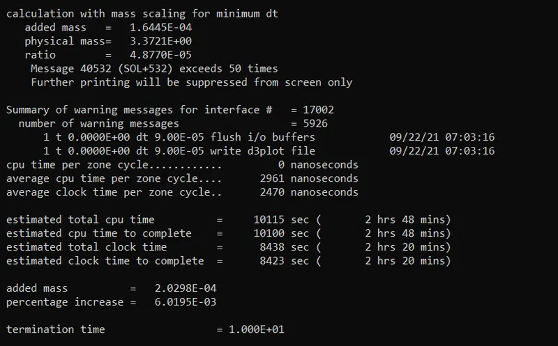
We can add artificial mass to decrease the time for simulation, DT2MS can be increased upto 8% of physical mass.
Let, DTMS= -0.1E-04
We can see the total time estimated to run the simulation is decreased to 2 hrs 20 mins.
We can add artificial mass to decrease the time for simulation, DT2MS can be increased upto 8% of physical mass.
we have to increase the value of DT2MS to see the effect
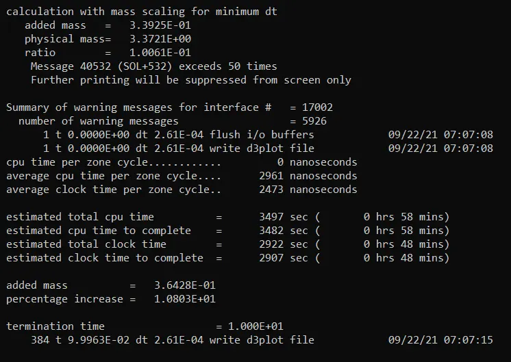
let, DT2MS = -2.9 e-04
We can see the total time estimated to run the simulation is decreased to 48 mins.
The mass percentage increase is exceeding 8%.
Therefore decrease the DTMS value to maintain the stability due to mass scaling.
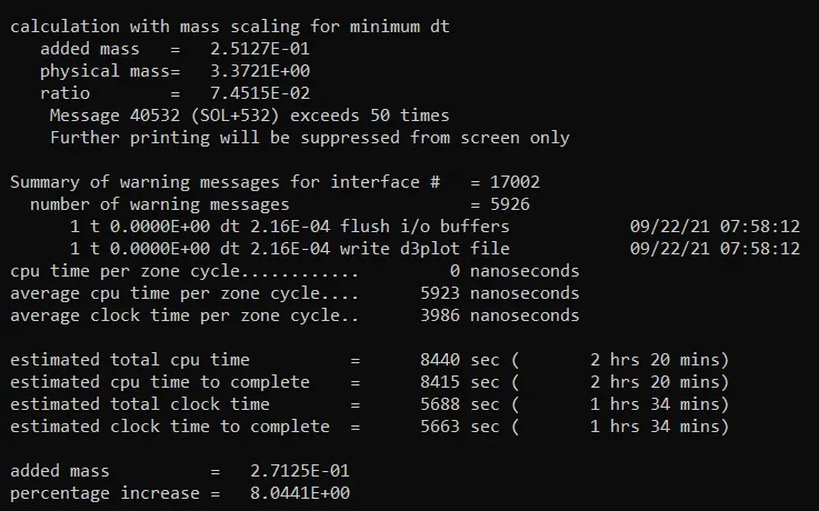
let, DT2MS = -2.7 e-04
We can see the total time estimated to run the simulation is decreased to 1hrs 34mins.
The mass percentage is almost 8% and which can maintain the stability due to mass scaling.
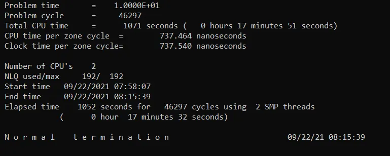
The total time taken for the simulation to complete is 17 mins and 32 seconds.
10. Post-processing:
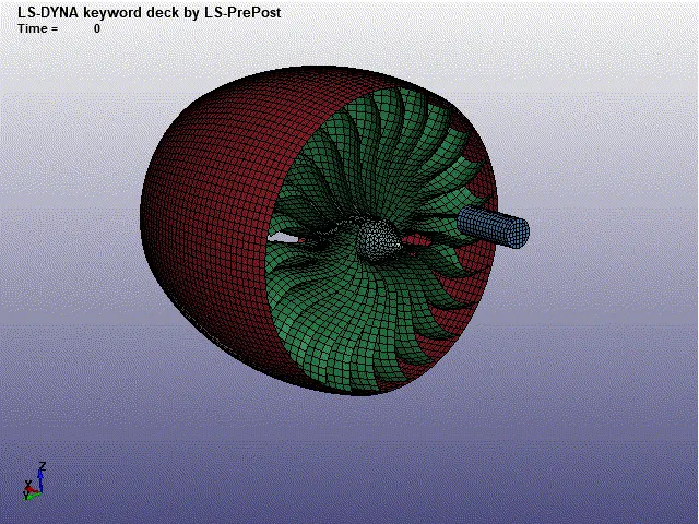
Animation of the simulation
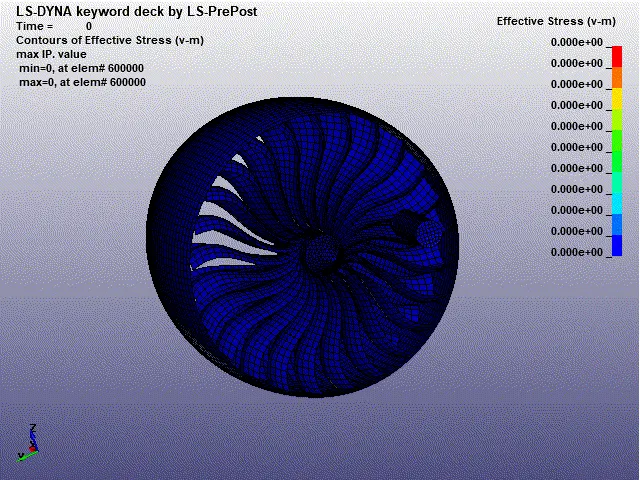
Von-mises stress contour:
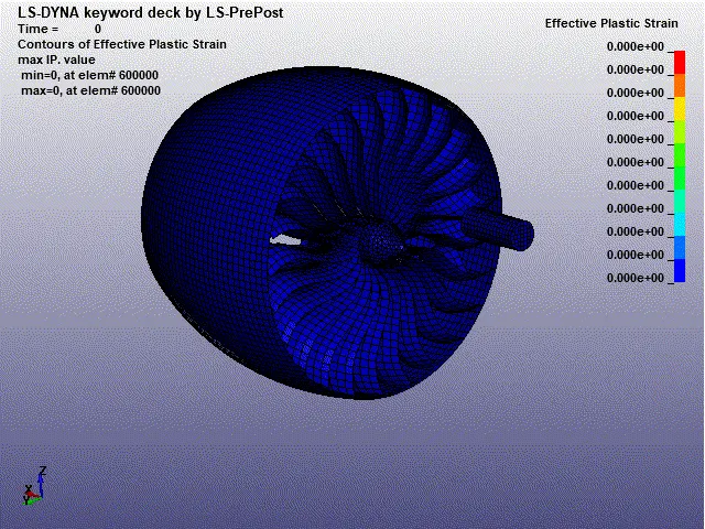
Effective_plastic_strain:
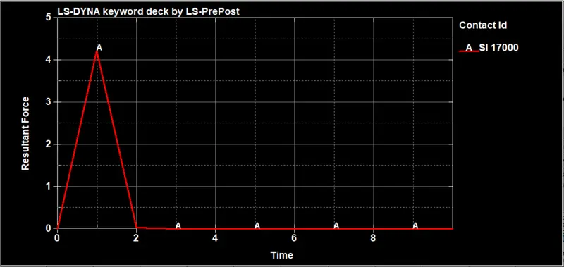
The resultant force between the blades and the bird during the impact:
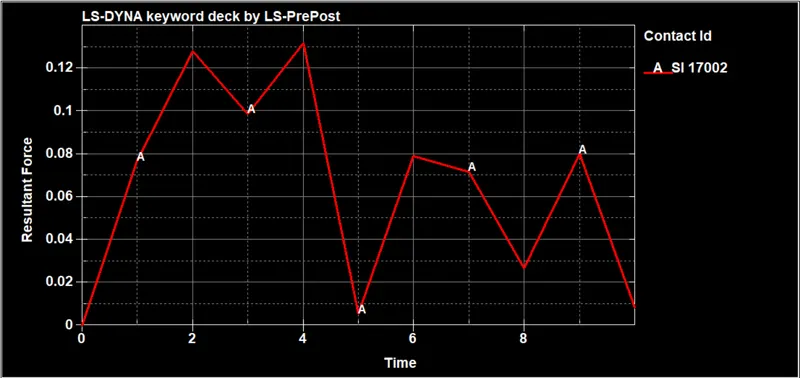
The resultant force between the blades and the casing during the impact:
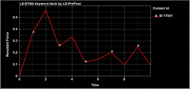
The resultant force between the blades and the hub during the impact:
Open the glstat file in ASCII
We can see how energies are varying
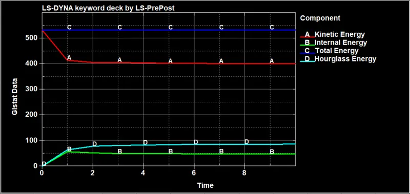
Kinetic energy, Internal energy, Total energy, Hourglass energy are plotted in the above figure
We can see the Internal energy at the start of simulation is zero and kinetic energy at the start is maximum.
A soon as the impact happens the kinetic energy decreases till the impact and remains constant throughout.
The inernal energy increases as the impact happens and remains constant after the impact.
We can see there is lot of hourglass energy is generated in this case.
Hourglass yield depends on the natural yield.
Hourglass loading stiffness depends on natural tangent modulus.
The hourglass treatment is done at material level.
Hourglass modes are non-physical modes of deformation that occur in under integrated elements and provide no stress.
Under integrated elements refers to
- solid element with single integration point
- shell element with single in-plane integration point
11. Conclusion:
- The bird strike on aircraft is simulated and the results are plotted.
- In this project, We have lernt how to organise the input keyword files similar to professional setting when dealing with large models and multiple people working with the same model simultaneously.
- To reduce the run time of the simulation, mass scaling approach is used.
-
If any changes are requires to make, change it in the parent file.Never edit any thing in the main include file, which may lead to many errors.