Bird Strike - Project - 2
AIM
Bird Strike on Aeroplane Turbine
OBJECTIVE
- Re-numbering the FEM parts
- Assigning all FEM parts to separate file.
- Assigning all the necessary keywords into separate file.
PROCEDURE
- Re-numbering different FEM models into different file.
According to the question all the fem models have to renumbered nodes, elements and parts.
Renumber <
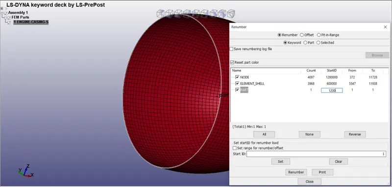
Nodes = 100000+
Elements = 500000+
Parts = 1000+
Similarly other fem models have to renumbered.
Casing
Nodes = 1200000
Elements = 600000
Parts = 1200
Blades
Nodes = 1500000
Elements = 800000
Parts = 1500
Hub
Nodes = 1800000
Elements = 1000000
Parts = 1800
Bird
Nodes = 2000000
Elements = 1200000
Parts = 2000
- Creating Section cards
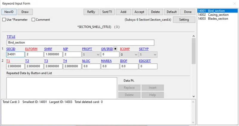
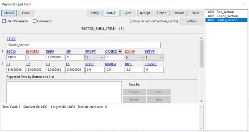
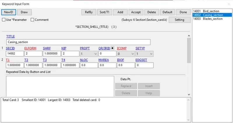
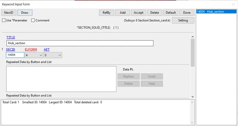
SHELL section is defined for Bird, Blade & casing and SOLID section for Hub. This section is saved in separate file.
Model < Keyword < Section <Shell
Model < Keyword < Section < Solid
This solid section has Element formulation as 4.
- Creating Material Cards
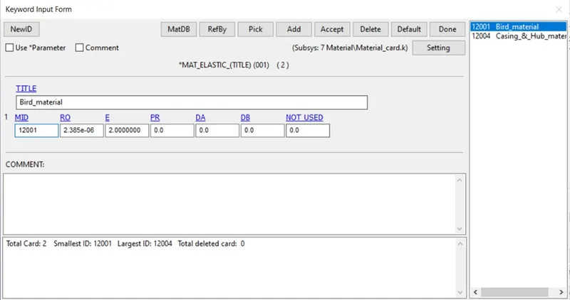
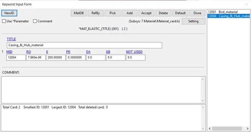
Material of Blade is defined and Bird, Casing & Hub is Elastic material.
Model < Keyword < Mat < Elastic
- Assigning parts
The MID & SECID is noted down and parts are assigned on their respective parts file.
Model < Keywords < Parts
- Creating Boundary Condition Cards
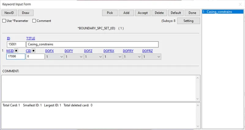
All Boundary conditions are defined on separate file. First SPC is created for casing Constrained.
Model < Keyword < Boundary < SPC
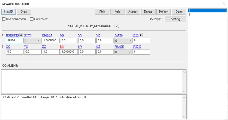
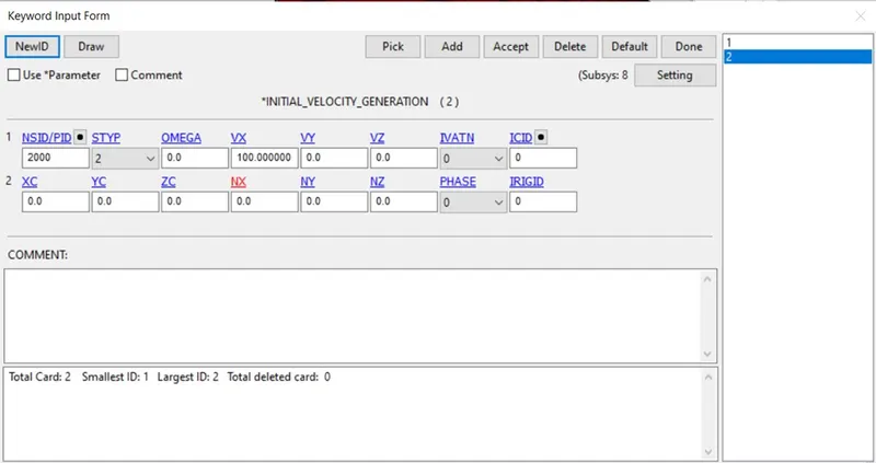
Since the velocity of Blade is constant so initial velocity generation card is created for blade as well as bird.
Model < Keyword < Initial < Velocity generation
Angular velocity is 1 rad/ms
Bird motion is 100mm/ms
- Creating Controls Cards
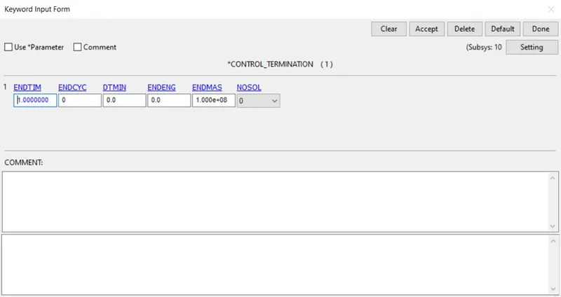
Termination card is defined for end time of simulation.
Model < Keyword < Control < Termination
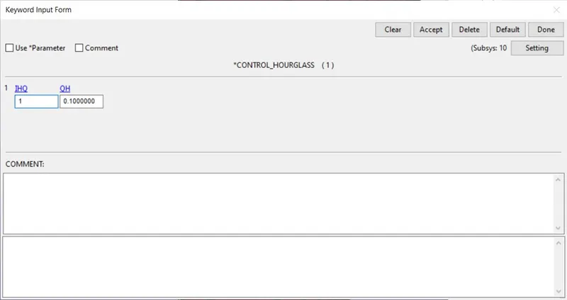
Hourglass is also defined.
Model < Keyword < Control < Hourglass
- Creating Contact cards
Automatic Surface to surface contact is defined between Bird and Blades.
Model < Keyword < Contact < Automatic Surface to Surface
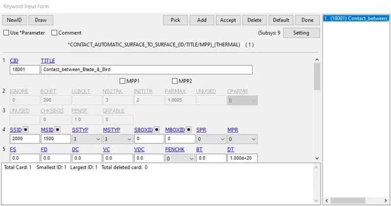
Tied Shell to edge to Surface contact is defined between Hub and Blade.
Model < Keyword < Contact < Tied Shell Edge to Surface
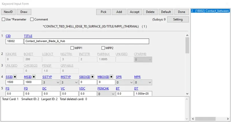
- Creating Database
ASCII and D3PLOT is defined.
Model < Keyword < Database < ASCII
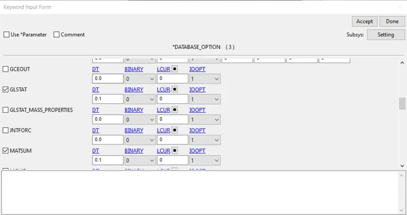
Model < Keyword < Database < Binary D3plot
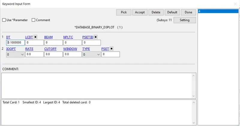
- Attaching all files in one main file
Model < Keyword < Include < Include
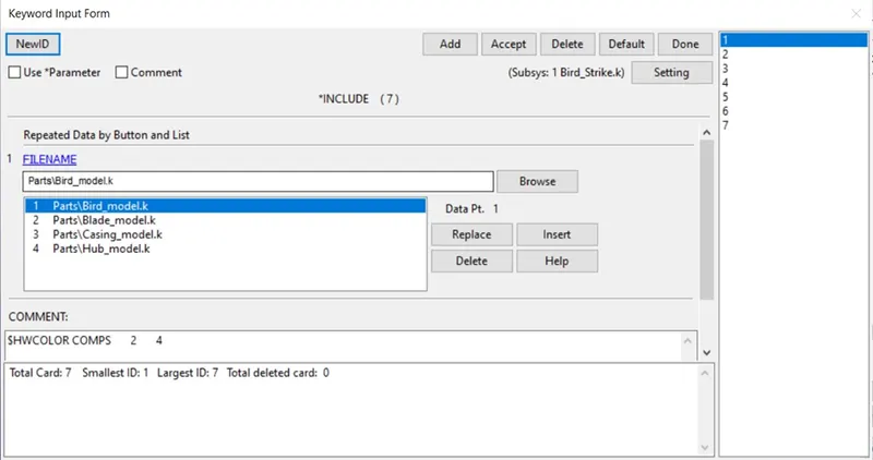
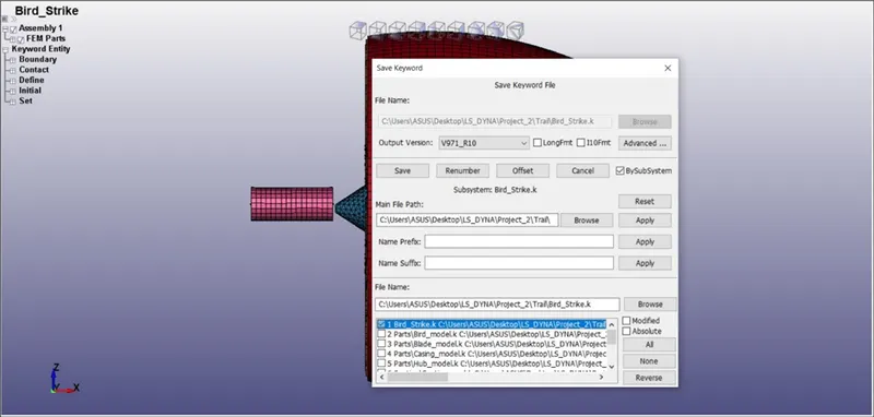
- Save file
After including all the parts and keywords file.
File < Save As < Save Keyword As
- Simulation
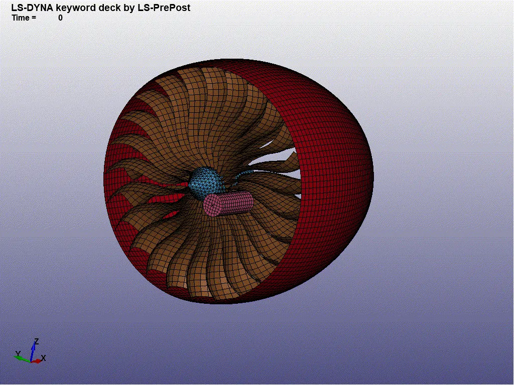
RESULTS
Von mises stress plot.
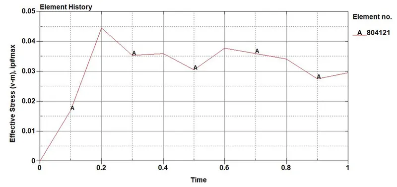
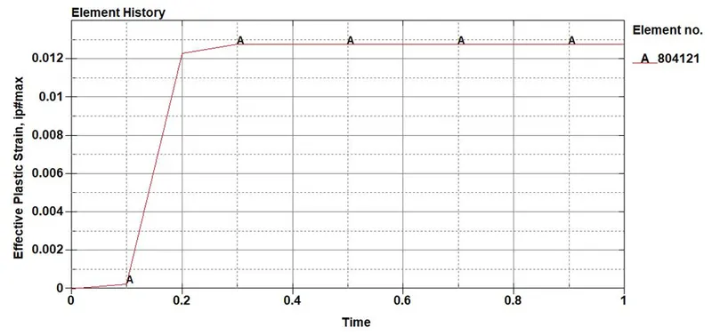
Effective Plastic strain plot
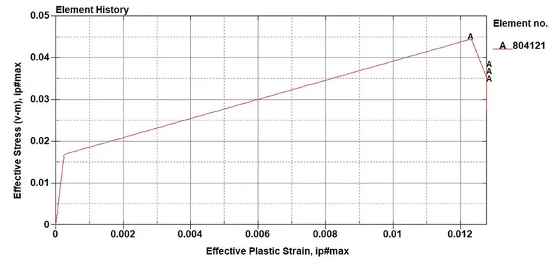
Stress vs Strain plot
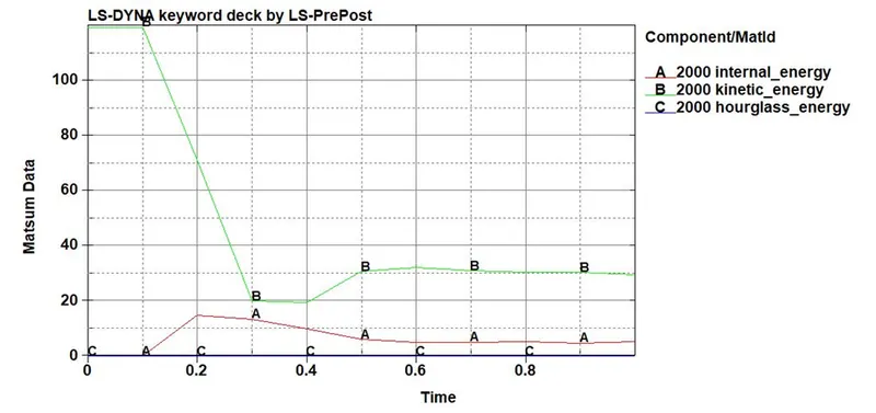
Energy plot
CONCLUSION
The Bird strike simulation was done with the help of shell and solid element using explicit method.
FUTURE
The future approach can be done by increasing the velocity and modifying positions.