Bird Strike - Project - 2
AIM:
To perfom and simulate non-linear transient birdstrike where the bird tried to hit the gas turbine blade by using explicit analysis LS-DYNA.
OBJECTIVE:
- The FE model consists of 4 parts that need to be separated and save part-wise. The suitable material is created and saved in a subfolder.
- The node number, element number and part number are assigned as mentioned above. Also, to conclude the final simulation create the main file the *INCLUDE file and run the explicit simulation using mass scaling.
PROCEDURE:
PART CREATION-
- Firstly we will open the .K file in LSPP.
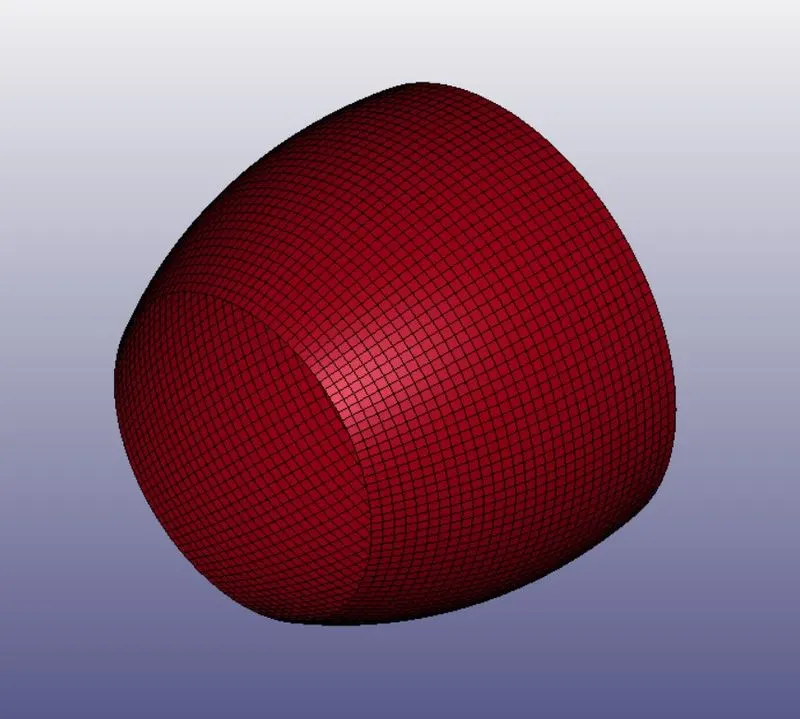
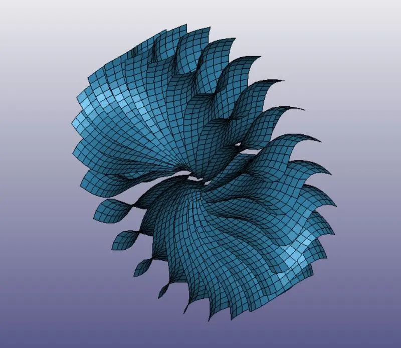
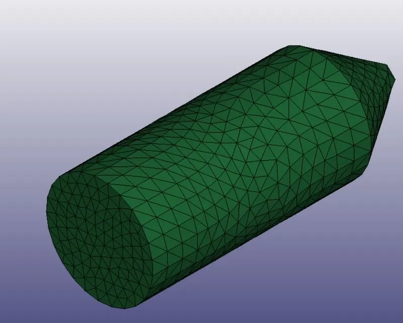
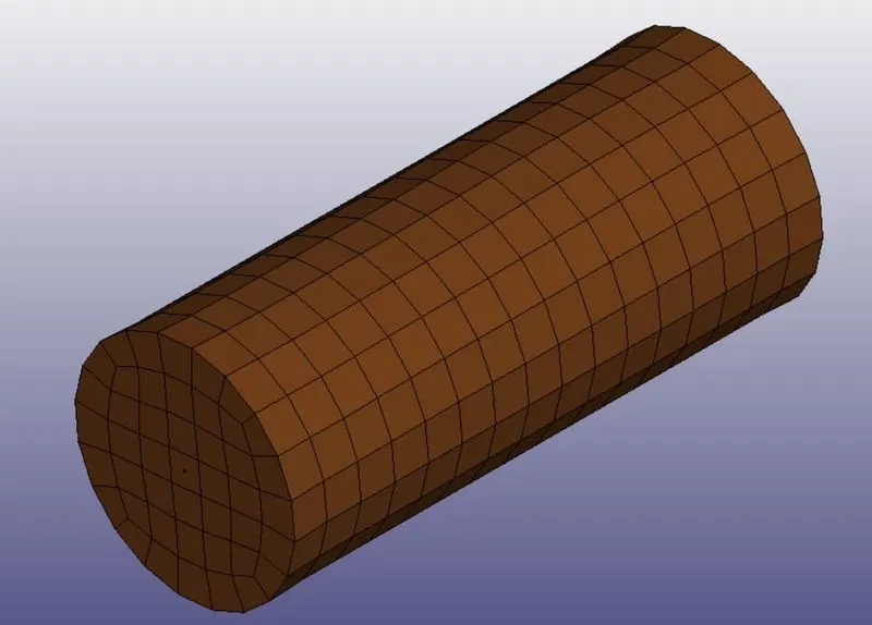
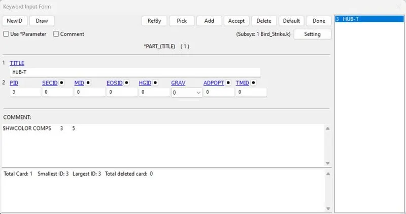
- Here we can see that there are all four parts are available (Hub,Casing,Blades and Bird).
- Now we have to create a new keyword with each individual parts.
- For that go to part and select one part, rest from that are deleted and saved as particular file name.
MATERIAL & SECTION CREATION-
- For each individual part which was created we will assign section and material.
BIRD MATERIAL-
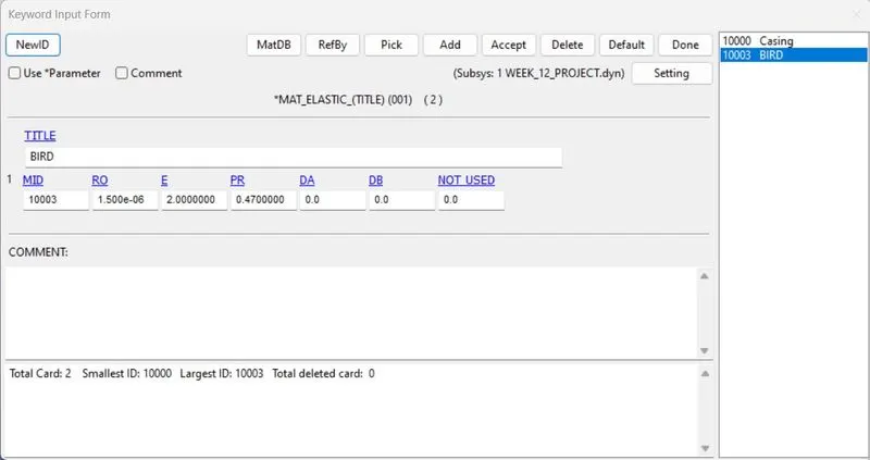
- The material and section card is created for assigning to the part created with the unit system KG-MM-MS.
- An new keyword file is opened in LS-PREPOST which is mainly for section and material.
- Here the material for bird is taken from research paper-https://www.researchgate.net/publication/258630404_Bird-Strike_Modeling_Based_on_the_Lagrangian_Formulation_Using_LS-DYNA
- As the bird is a soft material that's why it's density has 2.0e-06 which is given.
- Youngs Modulus of the bird is given as 2GPA and poissio's ratio is 0.47.
ENGINE CASING-
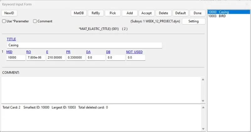
- Now for engine casing we will assign the MAT_ELASTIC card with property of steel.
ENGINE BLADES-
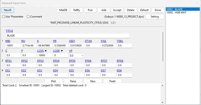
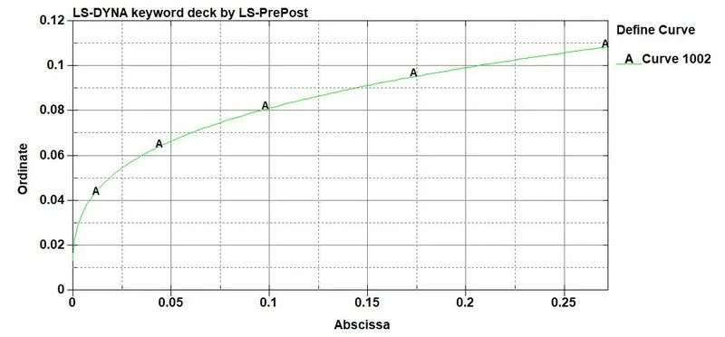
- For blades we will select MAT_024_PIECEWISELINEAR_PLASTICITY is assigned with aluminium property and as given we will insert MAT_curve from the given data.
TURBINE HUB-
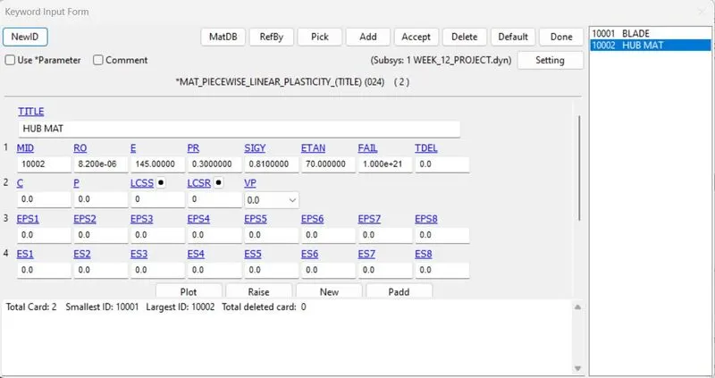
- For turbine hub we will use the same material card 024_PIECEWISE_LINEAR_PLASTICITY is assigned with steel properties.
SECTION CREATION-
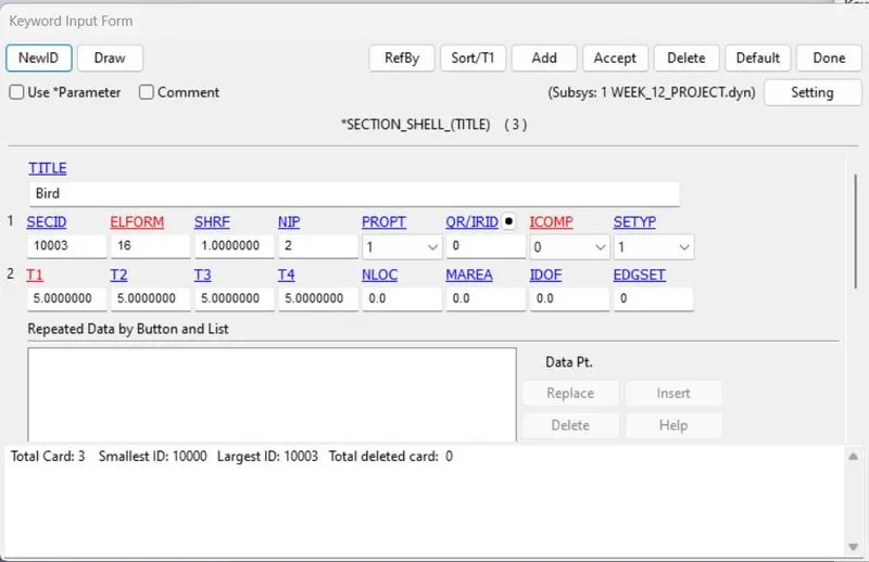
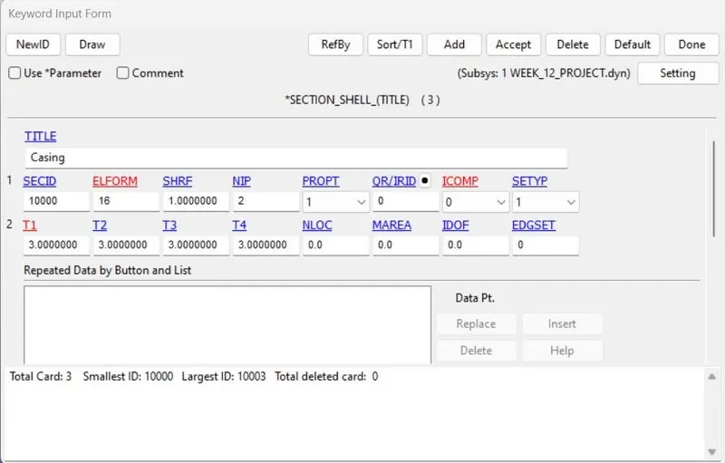
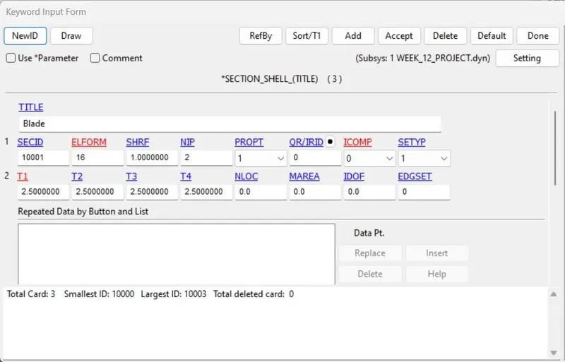
- Here the engine casing, bird and blade are modelled with shell elements, hence we will use section as shell with respective thickness and ELFORM.
- Now for Hub we will use solid section for modelling.
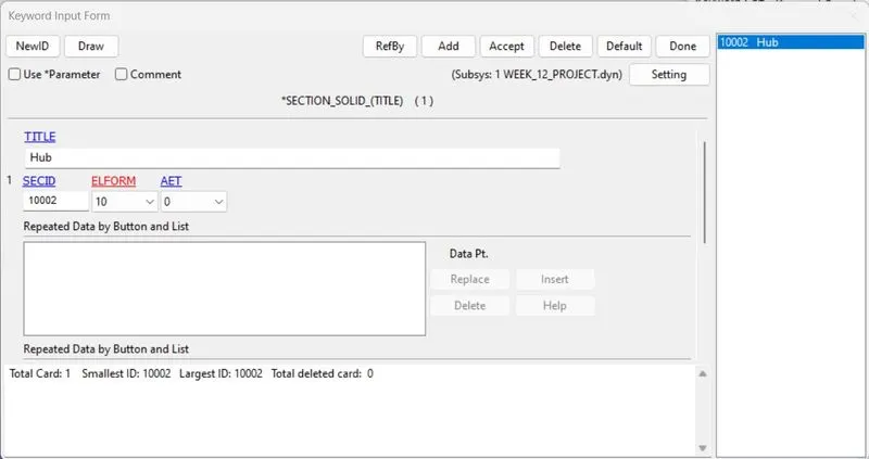
- Each Keyword file with respective material and sections are saved individually.
INCLUDE-
- Now we will call all the model in a single file for which we will use command called INCLUDE. For this in keyword we will selecting the Include in Include option.
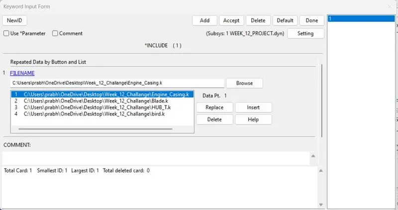
- Here the include file is saved as WEEK_12_PROJECT.dyn extension for easy access the new keyword which consists of parts with their respective section and material.
CONTACT CREATION-
- As their are movement of all the subparts with respect to each other and also their is considence of parts hence for this we need to define contacts to all the sub parts.
- As this project is for Bird strike on the engine blades, so the contact should be AUTOMATIC_SURFACE_TO_SURFACE here bird is selected as slave and blade is selected as Master.
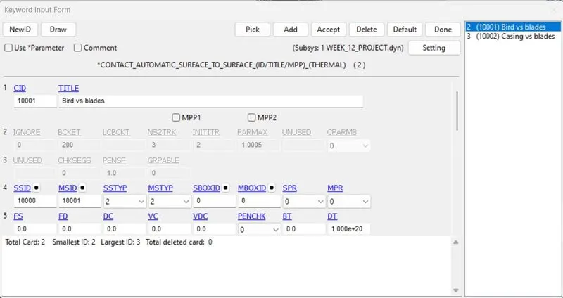
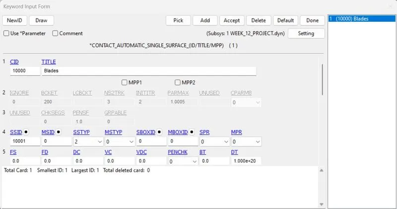
- Now after impact there is a high chances of blades getting broken in pieces and collide with each other, for this we will assign AUTOMATIC_SINGLE_SURFACE considering Blades as slave and not assigning any master.
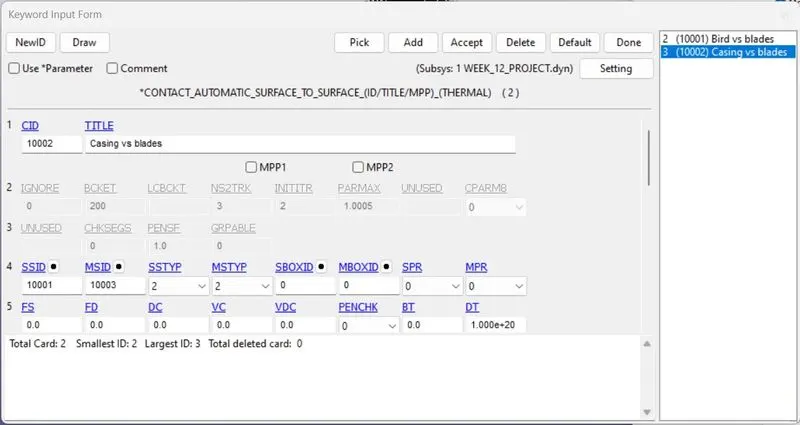
- During the impact the blade might get broken and chances of hitting the casing, for this we will assigning AUTOMATIC_SURFACE_TO_SURFACE contact where Casing is master and Blades as slave.
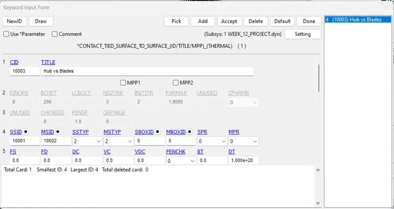
- Now as Hub and Blades are rotating we will use TIED_SURFACE_TO_SURFACE contact to tie those two part with each other, here we will take Hub as master and Blades as Slave.
BOUNDARY CONDITIONS-
INITIAL VELOCITY:
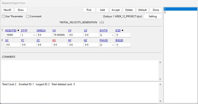
- The average velocity in which bird travel is taken from outside source and it's found to be approximated as in between 20 to 80 mm/ms which may vary according to the weight of the bird.
- As the weight of the bird is around 9.126E-06 kg which is very less so the minumum velocity is assigned for the bird as 75 mm/ms along X-Axis.
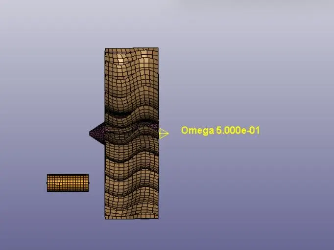
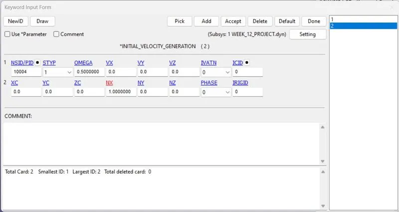
- For the Blades and Hub angular velocity must be defined. As the avg. spped of turbine is around 3000 to 20000 RPM.
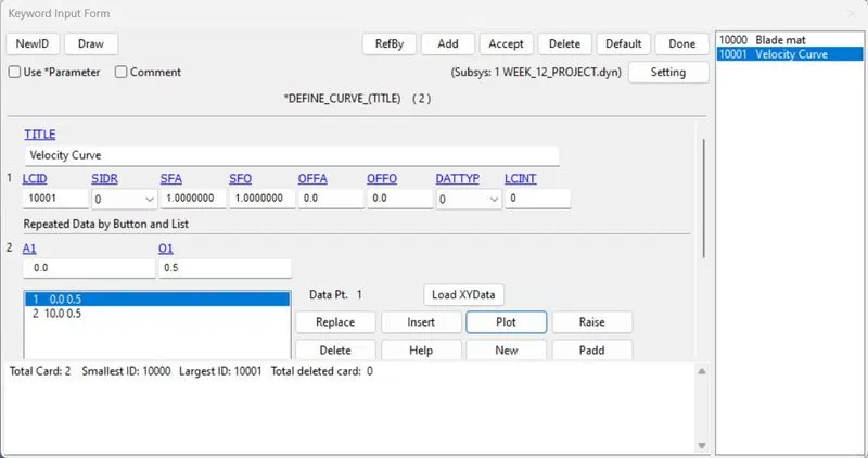
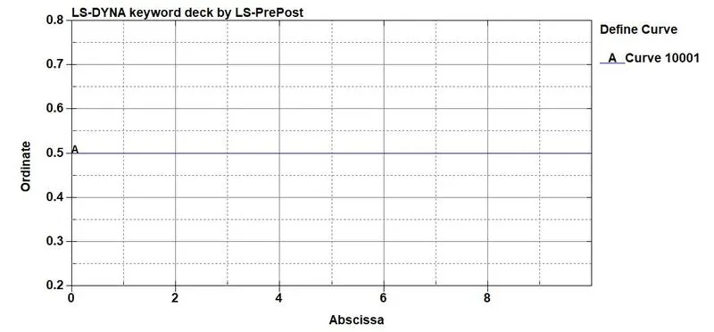
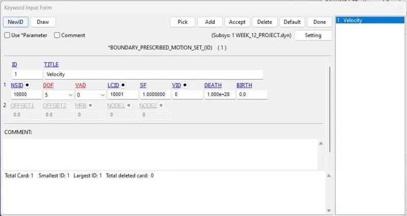
- Here we will consider the RPM as 5000 which is 0.5 rad/ms. And the Angular velocity is given as 0.2 rad/ms along X-Direction.
SPC-
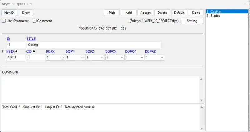
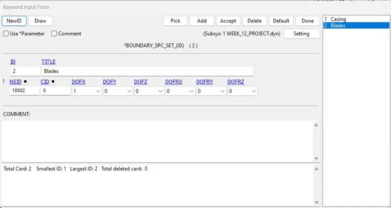
- The casing is constrained in all the axis of DOF as it should be fixed at the time of impact.
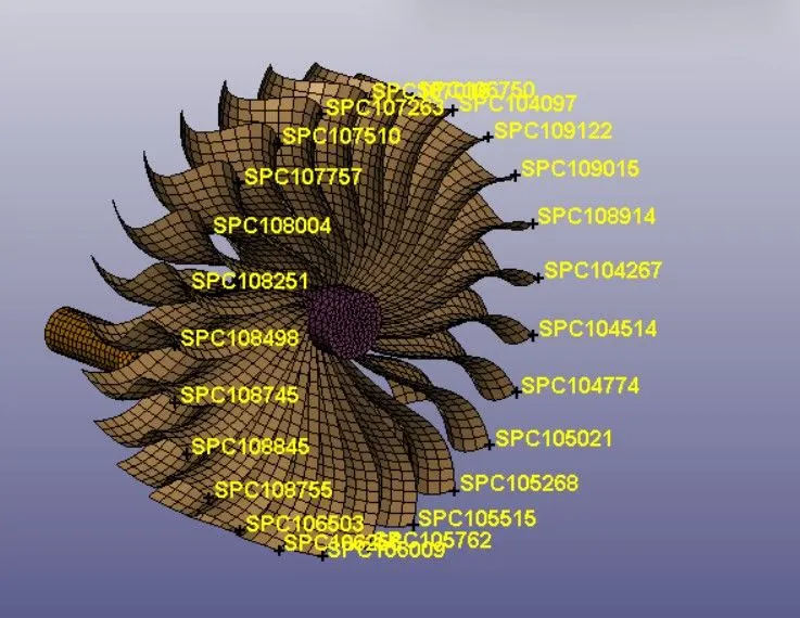
- The Blades and the Hub should not be moved at the time of impact so the corners of the blades are constrained in X-axis.
BOUNDARY PRESCRIBE MOTION SET-
- At the time of Bird Impacting on the blades, the velocities of the blades might get reduced, which is against the real time scenario so prescribe motn is assigned to the Hub and the blade to maintain a constant velocity.
CONTROL CARDS-
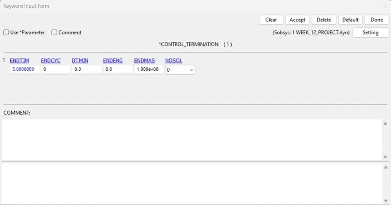
- Run time of the simulation is set for 5ms using CONTROL_TERMINATION card.
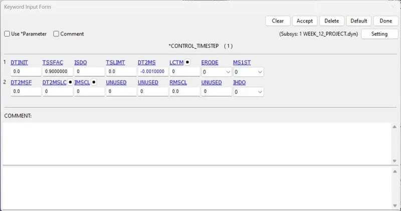
- For performing the simulation faster CONTROL_TIMESTEP card is assigned with random mass scaling value.
OUTPUT REQUEST-
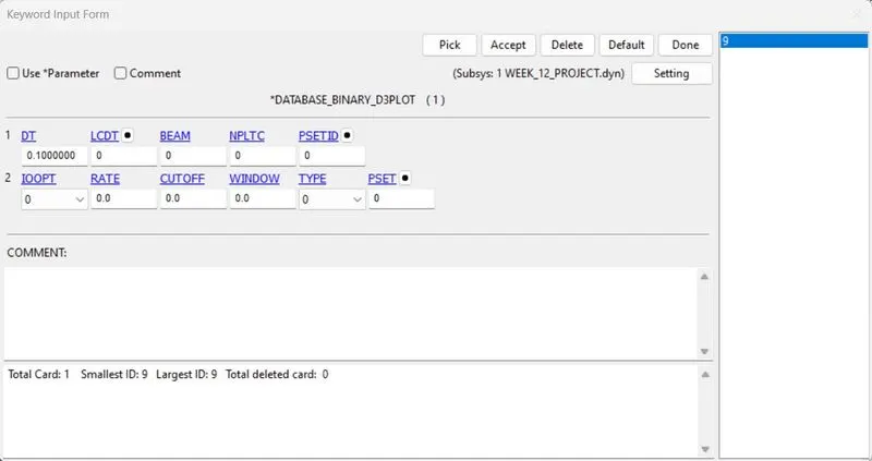
- BINARY_D3PLOT is defined for the frequency at which the animation files to be created.
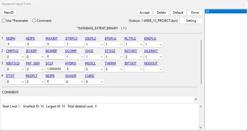
- DATABASE_EXTENT_BINARY is also defined for writing the strain tensor data to the D3PLOT when STRFLG is set to 1.
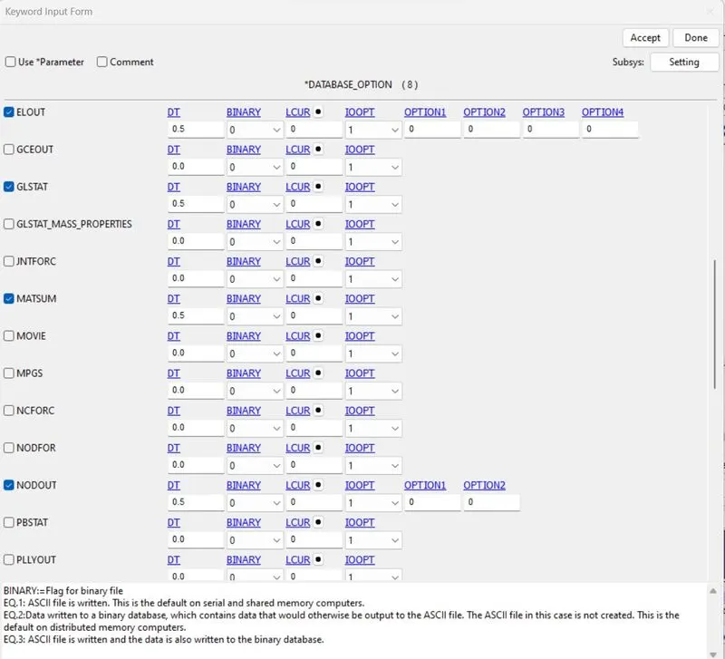
- Now we will also assign ASCll option with DT value as 0.5.
RENUMBERING ID'S-
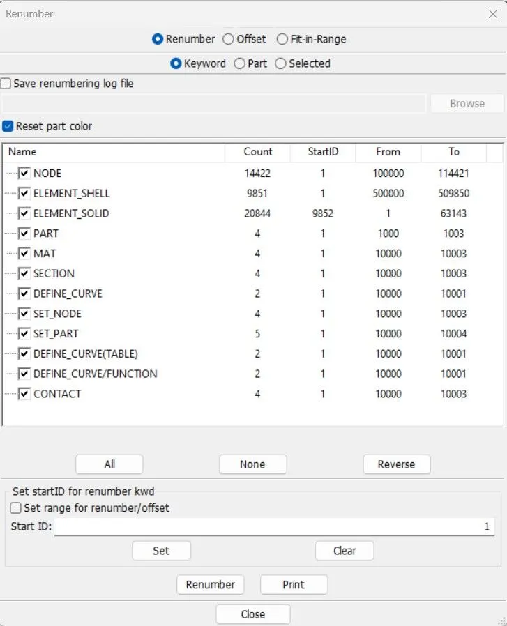
- Each part of the model setup is opened in LS_PP individually and their node,element and part id's are renumbered accordingly in such a way that 100000+ for nodes, 500000+ for elements and 1000+ for the parts. This method follows a consistent numbering approach which is used commonly in industries that deals with more complex projects.
RESULT:
- We will check the model and then running the .k file for simulation.
- As the thickness of the bird is given as 5mm and the thickness of blade is 2mm it is seen that the bird hitting the blade and it's getting broken due to the impact of the bird velocity. Due to imposed velocity given blade doesn't stop after the impact. And due to centrifugal force the bird initially pulled into blade and moved away due to contact with other blade.
- The Maximum stress acting during the impact is 0.102 GPA at element 508083.
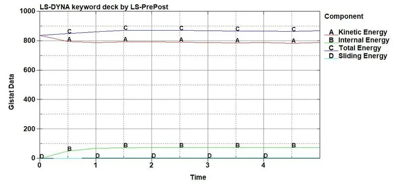
- From the graph, we can see that the bird impact which is in the form of kinetic energy, the blade deforms, Correspondingly the internal energy of the system starts acting in opposite direction to the kinetic energy so, the plots satisfies the law of conservation of energies.
- As a result the total energy of the system remains in Lineae mode throughout the impact.
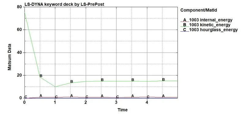
- From the graph we can see that the kinetic energy of the bird is decreasing at the time of impact and remains constant after 2ms.
- As the bird is less in size and mass the internal energy produced by the bird is very less.
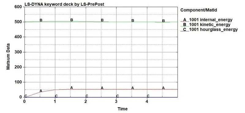
- From the graph we can clearly see that the kinetic energy of the blade remains constant because of imposed velocity given to it.
- The internal energy produced by the baldes are sufficient to its properties and comparitiveley acceptable with the internal energy of bird.
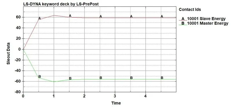
- Contact energies due to contact automatic surface to surface is used between bird and blades considering blades as master and bird as slave.
CONCLUSION:
- The Bird Strike on an aircraft engine simulation was carried out using LS-DYNA and the result are plotted.
- Here we have learned to create and organize the input keyword files similar to professional setting when dealing with the large model and multiple components.