Bird Strike - Project - 2
OBJECTIVE :
To perform the simulation of bird strikes in an aero engine model using LS DYNA. This is a classic nonlinear transient dynamics problem similar to a car crash and mobile drop. While accurate modeling of the problem requires advanced techniques such as SPH, this problem can be solved using a generic explicit solver.
Some main information’s that required to model the phenomenon.
- The blades should rotate at a constant velocity but the casing should remain stationary. The cylindrical bird model should travel along its own axis and hit the blades. Use elastic material for the bird(2000MPa) and the casing(200GPa). The velocity of the engine blades and the birds can be chosen so that blade failure can be seen within a short span of time.
- Need to follow a consistent numbering approach of 100000+ for nodes, 500000+ for elements, and 1000+ for the parts. All other keywords should be numbered within 10000-19999 while following a range for each one.
- The bird, casing, and blades should be in different input files and there should be one main file referencing all the input files. The main file should contain only references. Control cards and boundary conditions should be there in another separate file.
- The reference includes path should be such that the folder can be copied anywhere and it is able to correctly reference all the files and run the simulation.
PROCEDURE :
Step (1): Separating all parts and saved all other sub-files in different names.
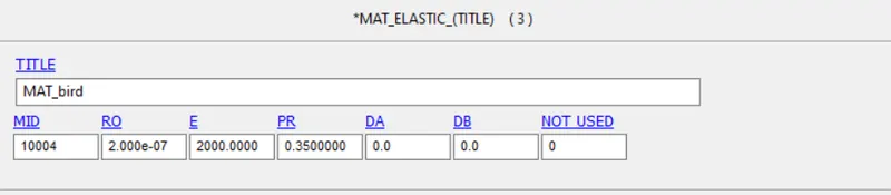
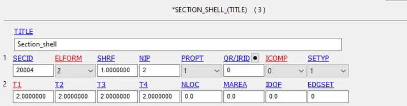
For bird :
- Opened the given original file all the parts are deleted except the bird.
- Assigning the material and section cards to the part keyword and images of material and section cards are shown below.
- Saved the file with a different name.
For Casing :
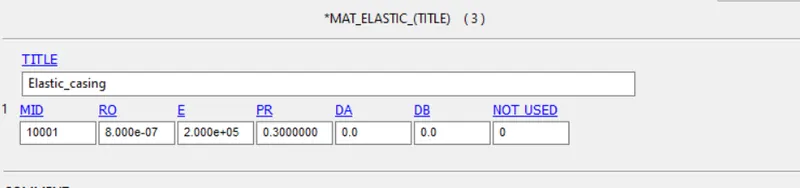
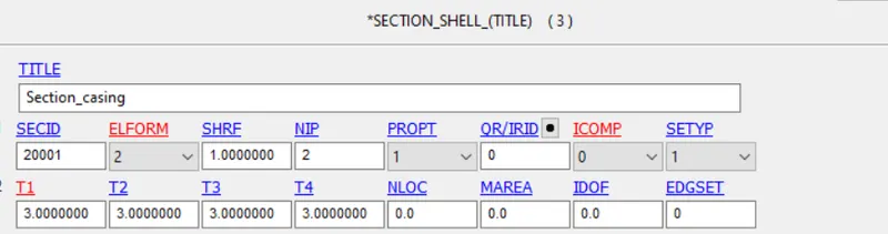
- Opened the given original file all the parts are deleted except the casing.
- Assigning the material and section cards to the part keyword and images of material and section cards are shown below.
- Saved the file with a different name.
For blades :
- Opened the given original file all the parts are deleted except blades.
- Assigning the material and section cards to the part keyword and images of material and section cards are shown below.
- Saved the file with different name.
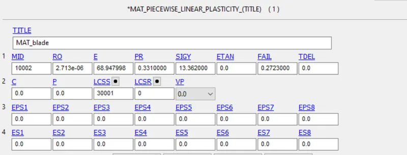
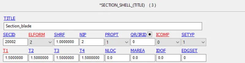
For hub :
- Opened the given original file all the parts are deleted except the hub.
- Assigning the material and section cards to the part keyword and images of material and section cards are shown below.
- Saved the file with a different name.
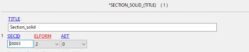
Step (2): Applying boundary conditions in a separate file
- Arresting all DOFs of the casing using the boundary_spc_set keyword.
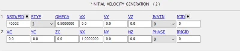
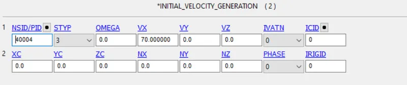
- The initial velocity generation keyword is used for giving the velocity for the birds part and angular velocity for blades as shown below.
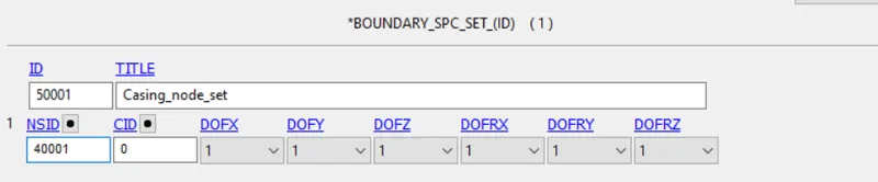
Step (3) : Applying contact cards
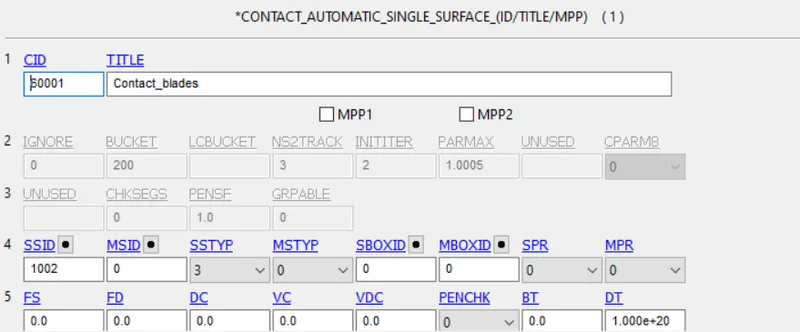
- Contact automatic single surface is used to define the contact between the blades as when the bird collides on the blades some blades may come in contact with each other so to define this we use this card.
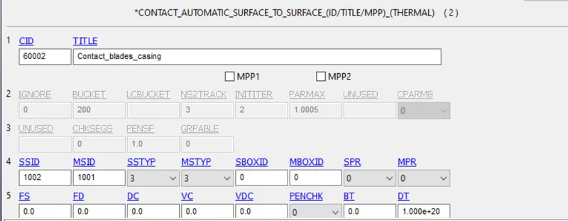
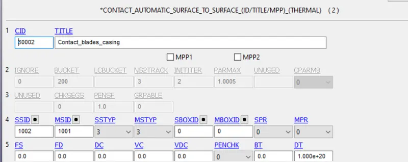
- Contact automatic surface to surface is used to define the contact between the blades and casing and bird and blades.
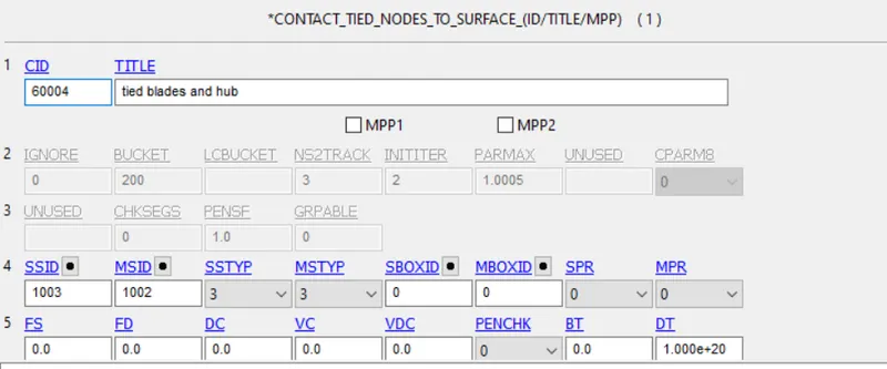
- Contact tied surface to surface is used to define the contact between the hub and blades
Step (4) : Assigning the control cards and database card in separate file
- Control termination card is used to give the endtime value.

- Control energy is used to reduce the hourglass effect.

- Control timestep is used for mass scaling to reduce the simulation time as this simulation involves more time to solve.

- Required outputs are obtained from database keywords.
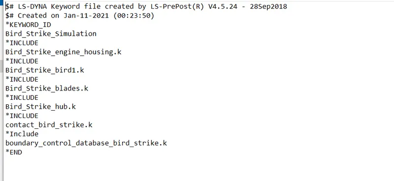
Step (5) : Include card is used to get all the files in one single major file.
- In the new empty file, all the included files are called into this major file as shown in the below image.
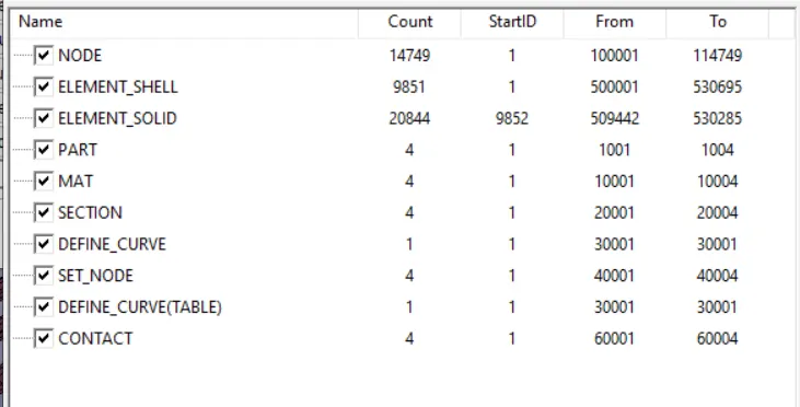
Step (6) : Renumbering the nodes, elements, part, material, section, curve, node set and contact.
Results and errors :
When the simulation started the error occurred due to because the contact definition surface to surface node sets should not be used as shown the below image.
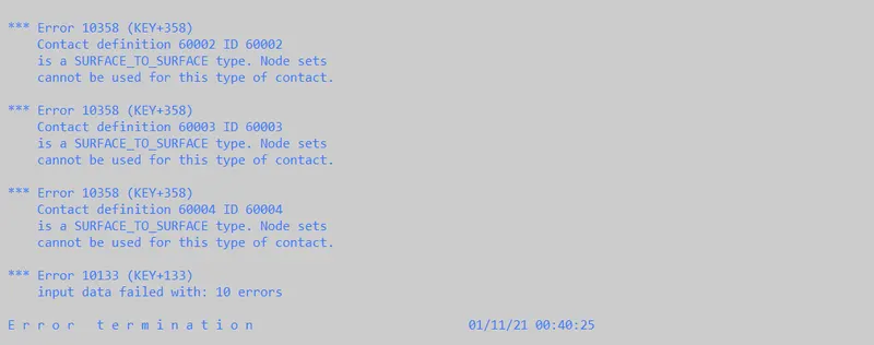
So instead of node set id, the part id is used to assign the contacts and every other thing is good to rerun the model.
Mass scaling
Since the model is a little bit complex so to run this model in the normal system going to take more time so to reduce this we can use mass scaling.
TSSFAC = 0.9, DT2MS = -4.5e-5
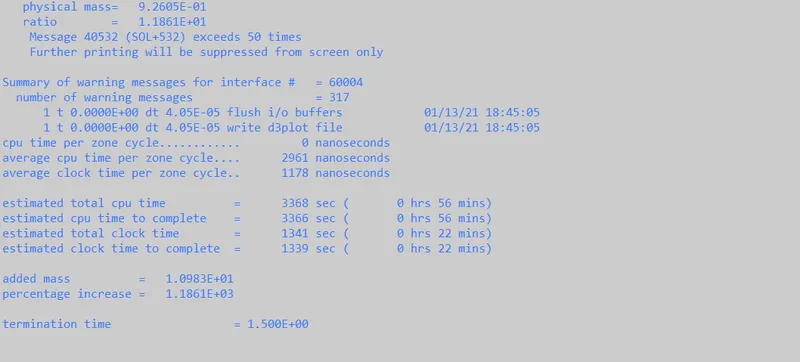
TSSFAC = 0.9, DT2MS = -9E-6
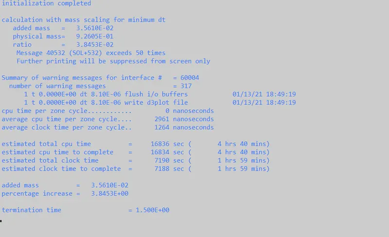
TSSFAC = 0.9, DT2MS = -9.9E-6
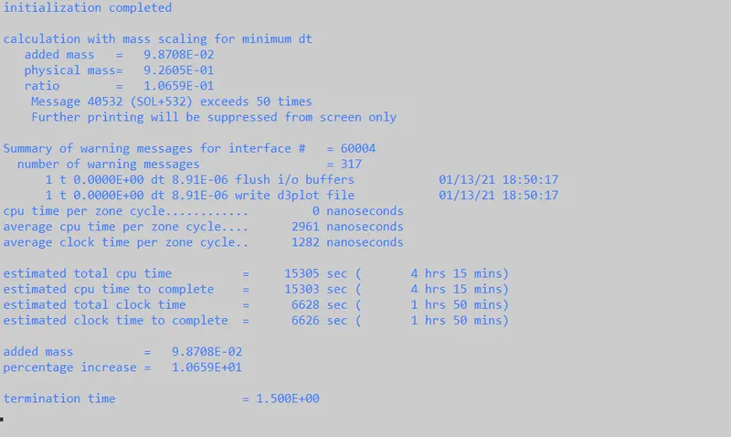
TSSFAC = 0.9, DT2MS = -9.8E-6
since the mass scaling percentage as to be below 10 percent so this is the best DT2MS AND TSSFAC values
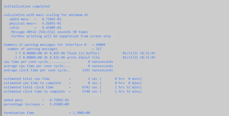
The below image shows a glimpse of the simulation carried out
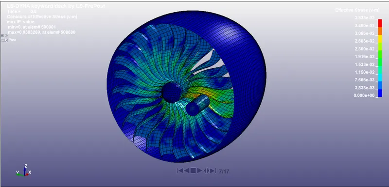
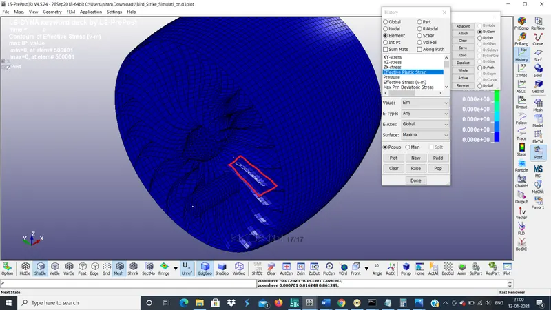
Below image shows the elements used for the stress and strain calculation
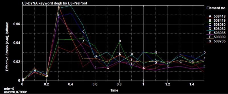
The below image shows the von misses stress of some of the blade elements and we can see the variation of stress when the bird is hitting it reaches maximum.
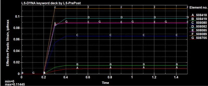
The below images show the variation of strain in the blade elements. When the bird hit on the blades some of the elements at the hit region shows high strain but also the strains of each elements vary that's due to the amount of energy it observed.
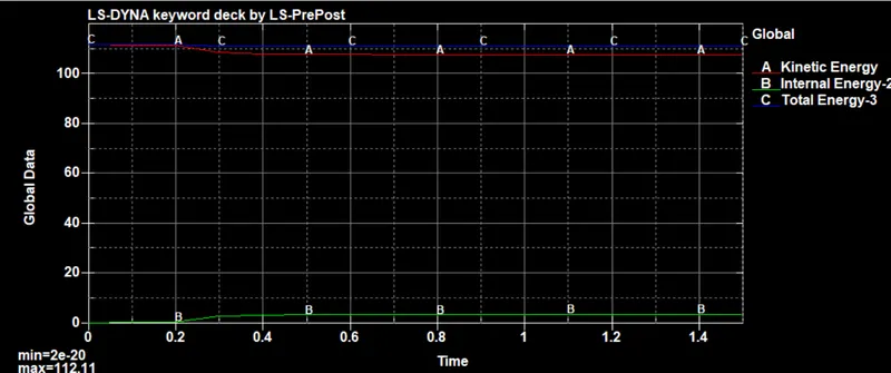
Below images show the variation of kinetic energy, internal energy, and total energy. When the bird strikes the blades the kinetic energy of the bird decreases and internal energy of the bird increases and total energy remains constant.
Conclusion :
The bird strike and aero engine model is built and simulation is carried out according to the given objective and requirements. The result and simulation show that it is almost similar to what is happening in nature and the data is also relatable and make sense.