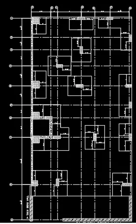
AutoCAD_Detailing of Wardrobe, Floor Plan, Kitchen Layout and Column Details_Week 6
CABINET
Aim: To draft the Cabinet using AutoCAD
Commands used:
- LINE
- OFFSET
- TRIM
- ERASE
- MLEADER
- DIMLINEAR
- TEXT
- CIRCLE
- ERASE
Procedure
- Open AutoCad
- Selecting metric system
- Command UN(units) and selecting decimals with precision of 0
- Command LIMITS and having limit of (0,0) in lower left corner and (10000,10000) in upper right corner
- Command ZOOM and selecting All
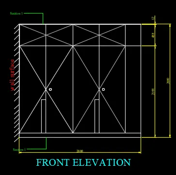
Drawing Front Elevation
- Command LINE and drawing a line of 2800mm horizontal and 2600mm vertical on four sides
- Command OFFSET and offsetting 12 mm on left side and top side of cabinet
- Command TRIM and trimming the unwanted lines
- Command OFFSET and offsetting 100 mm from the bottom line of cabinet
- Command OFFSET and offsetting 1223 from left offsetted line
- Command OFFSET and offsetting 1200 from offsetted line
- Command OFFSET and offsetting 365 from offsetted line
- Command OFFSET and offsetting 500 mm from the top line of cabinet
- Keeping Object snap ON and turning midpoint on
- Command LINE and Drawing a line from midpoint of left sided cabinet through out its length
- Command LINE and Drawing a line from midpoint of middle cabinet through out its length
- Command OFFSET and offsetting 100mm slightly below the centre line of left sided divider and drawing vertical line
- Command OFFSET and offsetting 100mm slightly below the centre line of middle cabinet divider and drawing vertical line
- Command LINE and drawing a horizontal line of 50mm from midpoint of left sided divider and middle cabinet divider
- Command CIRCLE and drawing a circle of 25mm from the point which line is drawn on both left sided divider and middle cabinet divider
- Command ERASE and Erase the unwanted lines
- Command TRIM and trim the unwanted lines
- Command LINE and keeping ortho off draw a cross lines for each cabinet both for bigger and smaller cabinet
- Command MLEADER and multileader style manager and modify in leader structure selecting maximum leader points as 3 and specfying points and type Section 1
- Command TEXT and angle 90 degree and typing as wall structure
- Command DIMLINEAR and dimensioning the Cabinet
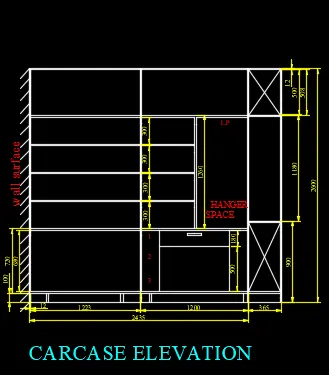
Drawing Carcase Elevation
- Command LINE and drawing a line of 2800mm horizontal and 2600mm vertical on four sides
- Command OFFSET and offsetting 12 mm on left side and top side of cabinet
- Command TRIM and trimming the unwanted lines
- Command OFFSET and offsetting 100 mm from the bottom line of cabinet
- Command OFFSET and offsetting 720 mm from the 100mm offsetted line of cabinet
- Command OFFSET and offsetting 20 mm from the 720mm offsetted line of cabinet both from top and bottom
- Command OFFSET and offsetting 12 mm and 300mm for the chamber respectively for 4 times
- Command OFFSET and offsetting 1223mm from left offsetted line from centerline
- Command OFFSET and offsetting 1200mm from offsetted line from centerline
- Command OFFSET and offsetting 365mm from offsetted line
- Command OFFSET and offsetting 900mm for 365mm portion
- Command OFFSET and offsetting 1180mm from 900mm line
- Command OFFSET and offsetting 12mm in the specified places
- For Stand OFFSET 400mm from the centerline of the left cabinet and offsetting for 50mm each on both sides
- Command LINE and keeping ortho off draw a cross lines for each cabinet for 365mm cabinet
- Command TEXT with height 50 and angle 0 type L.P, HANGER SPACE and 1 2 3 in specified place
- Command TRIM and trim the unwanted lines
- Command TEXT and angle 90 degree and typing as wall structure
- Command DIMLINEAR and dimensioning the Cabinet
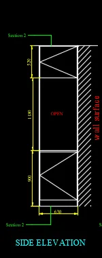
Drawing Side Elevation
- Command XLine to Horizontal of baseline on top and bottom
- Command OFFSET of 100mm from the baseline
- Command OFFSET of 900mm from the baseline
- Command OFFSET of 1180mm from the 900mm line
- Command OFFSET of 20mm below the 900mm line
- Command OFFSET of 12mm on left, right and top edge of cabinet
- Command LINE and keeping ortho off draw a cross lines for each cabinet both for top and bottom cabinet
- Command HATCH and selecting the ANS131 selecting the outer portion of the section 2
- Command MLEADER and multileader style manager and modify in leader structure selecting maximum leader points as 3 and specfying points and type Section 2
- Command TEXT and angle 90 degree and typing as wall structure
- Command DIMLINEAR and dimensioning the Cabinet
- Command TEXT and angle 0 degree and typing as SIDE ELEVATION
- Command TRIM and trim the unwanted lines
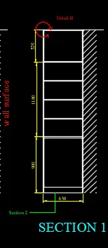
Drawing Section 1
- Command XLine to Horizontal of baseline on top and bottom
- Command OFFSET of 100mm from the baseline
- Command OFFSET of 900mm from the baseline
- Command OFFSET of 1180mm from the 900mm line
- Command OFFSET of 20mm below the 900mm line
- Command OFFSET of 12mm on left, right and top edge of cabinet
- Command OFFSET of 12mm and 300mm from 900mm line respectively for 4 times
- Command HATCH and selecting the ANS131 selecting the outer portion of the section 1
- Command ARC and selecting Start,center and end draw a arc on top left corner
- Select Arc properties and change the colour to red
- Command DIMLINEAR and dimensioning the Cabinet
- Command TEXT and angle 0 degree and typing as Section 1
- Command TRIM and trim the unwanted lines
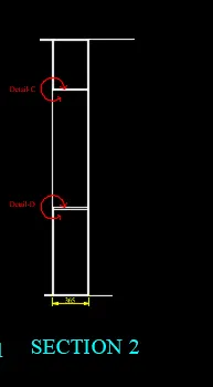
Drawing Section 2
- Command XLine to Horizontal of baseline on top and bottom
- Command OFFSET of 100mm from the baseline
- Command OFFSET of 900mm from the baseline
- Command OFFSET of 1180mm from the 900mm line
- Command OFFSET of 20mm below the 900mm line
- Command OFFSET of 12mm on left, right and top edge of cabinet
- Command OFFSET of 365mm from the left line
- Select Arc properties and change the colour to red and place in specified place
- Command DIMLINEAR and dimensioning the Cabinet
- Command TEXT and type Detail-C and Detail-B
- Command TEXT and angle 0 degree and typing as Section 2
- Command TRIM and trim the unwanted lines
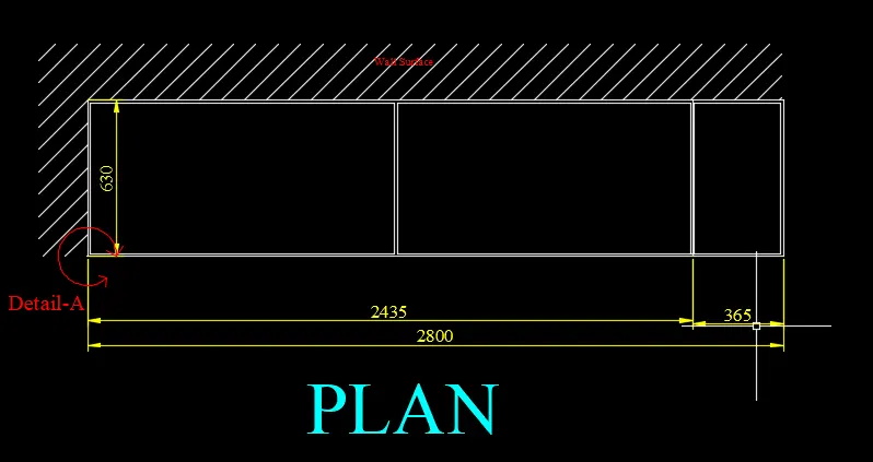
Drawing Plan
- Command XLine to Vertical of the Front elevation on both sides and on each chamber
- Command OFFSET 630mm
- Command OFFSET 2435mm
- Command OFFSET 365mm
- Command OFFSET 12mm on 4 sides and on each chamber
- Command TRIM and trim the unwanted lines
- Select Arc properties and change the colour to red
- Command DIMLINEAR and dimensioning the Cabinet
- Command TEXT and angle 0 degree and typing as PLAN
- Command TEXT and angle 0 degree and typing as Wall surface
- Command HATCH and selecting the ANS131 selecting the outer portion of the plan
- Command TEXT and angle 0 degree and typing as Wall surface
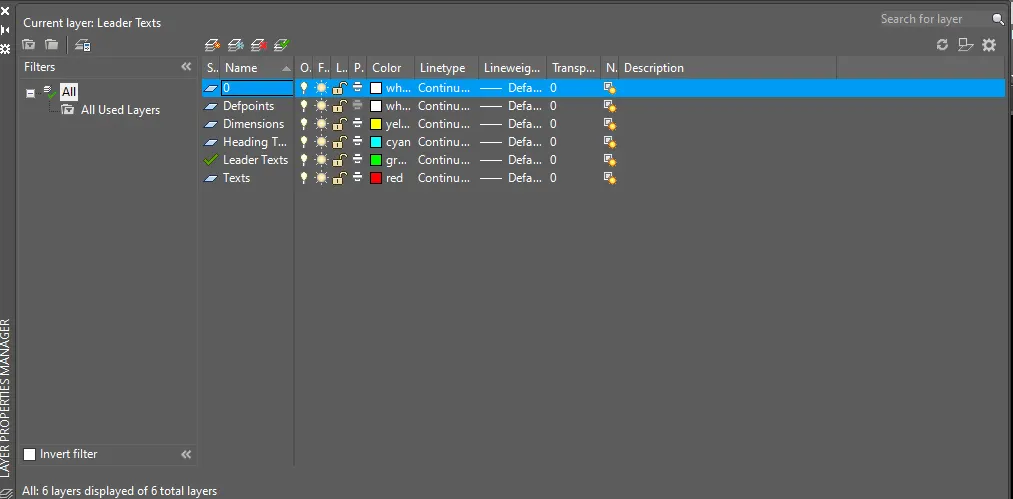
Adding Layer to the Drawing
- Command LAYER and adding Dimensions and giving yellow colour
- Command LAYER and adding Heading texts and giving cyan colour
- Command LAYER and adding Leader texts and giving green colour
- Command LAYER and adding Texts and giving Red colour
- Adding the Specified dimensions and texts to the specified layer respectively
Result:
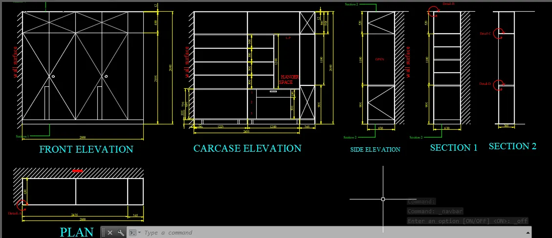
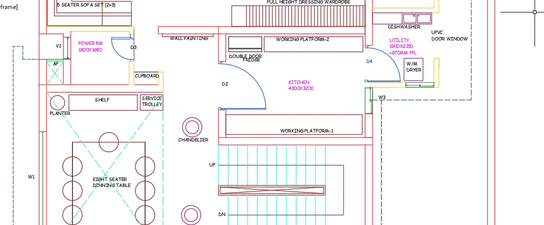
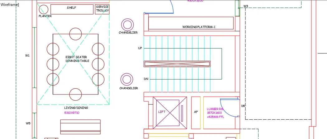
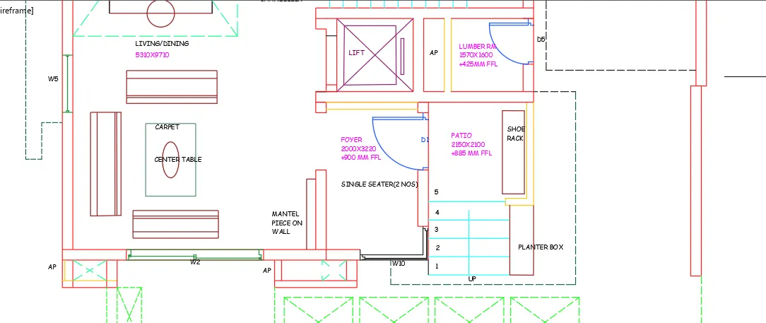
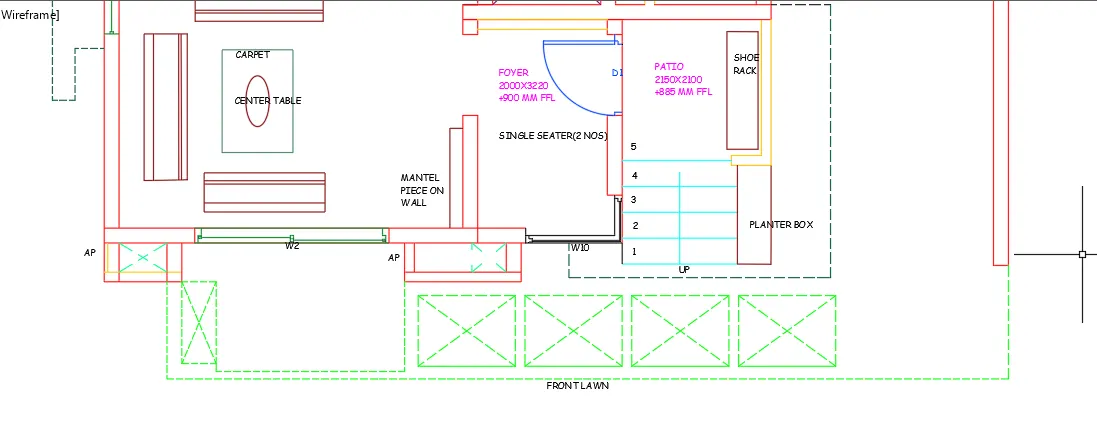
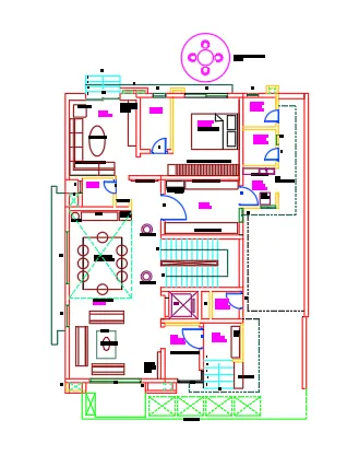
FLOOR PLAN
Aim: To draft the floor plan of the house and dimensioning it using AutoCAD
Procedure:
- Open AutoCad
- Selecting metric system
- Command UN(units) and selecting decimals with precision of 0
- Command LIMITS and having limit of (0,0) in lower left corner and (10000,10000) in upper right corner
- Command ZOOM and selecting All
Commands used:
XLINE
- XLINE horizontal and vertical is used to start the drawing initally
LINE
- LINE is used to draw the line in the Window, Doors, Ventilators, Staircase and lines at required spaces
OFFSET
- OFFSET is used to offset the external walls to 230mm and internal walls to 150mm
- OFFSET is used to offset the Living/Dining room to 5310mm horizontal and 9710mm vertical
- OFFSET is used to offset the Power RM to 1800mm horizontal and 1650mm vertical
- OFFSET is used to offset the Family to 3880mm horizontal and 4350 vertical
- OFFSET is used to offset the Toilet-01 to 1750 horizontal and 3000 vertical
- OFFSET is used to offset the Bedroom-01 to 3830 horizontal and 4500 vertical
- OFFSET is used to offset the Kitchen to 4300 horizontal and 3200 vertical
- OFFSET is used to offset the Lumber RM to 1570 horizontal and 1600 vertical
- OFFSET is used to offset the Patio to 2150 horizontal and 2100 vertical
- OFFSET is used to offset the Foyer to 2000 horizontal and 3220 vertical
- OFFSET is used to offset the Utility to 1900 horizontal and 2150 vertical
- OFFSET is used to offset the Utility RM to 1900 horizontal and 2100 vertical
- OFFSET is used to offset the D.H Toilet to 1900 horizontal and 1700 vertical
- OFFSET is used to offset the different lines to specified offsetting distance
PLINE
- PLINE is used to draw the Front Lawn points and Chejjas above the windows and ventilators
RECTANGLE
- RECTANGLE is used to draw the Side Table, TV Units, Sofa Sets in Family Room
- RECTANGLE is used to draw the Cupboard in Power RM
- RECTANGLE is used to draw the Shelf, Service Trolley, Carpet, Sofasets and Dining Table in Living/Dining Room
- RECTANGLE is used to draw the Lift
- RECTANGLE is used to draw the Working Platform-1 and 2 in Kitchen
- RECTANGLE is used to draw the Dishwasher and W/M Dryer in the Utility
- RECTANGLE is used to draw the Bed, Dressing Wardrobe and Pillow in Bedroom
TRIM
- TRIM is used to trim the unwanted lines
CIRCLE
- CIRCLE is used to draw the Planter, Dining Table Seats, Chandelier and Outdoor Seating
ARC
- ARC is used to draw the doors with Start,Center and End
LINETYPE
- LINETYPE is to change the Continuous line to Dash line and changing the scale to 20
ELLIPSE
- ELLIPSE is used to draw the Center Table with specifying the minor axis horizontal and drawing to specified length
LAYER
- LAYER is used to layer different components of Building to different layer
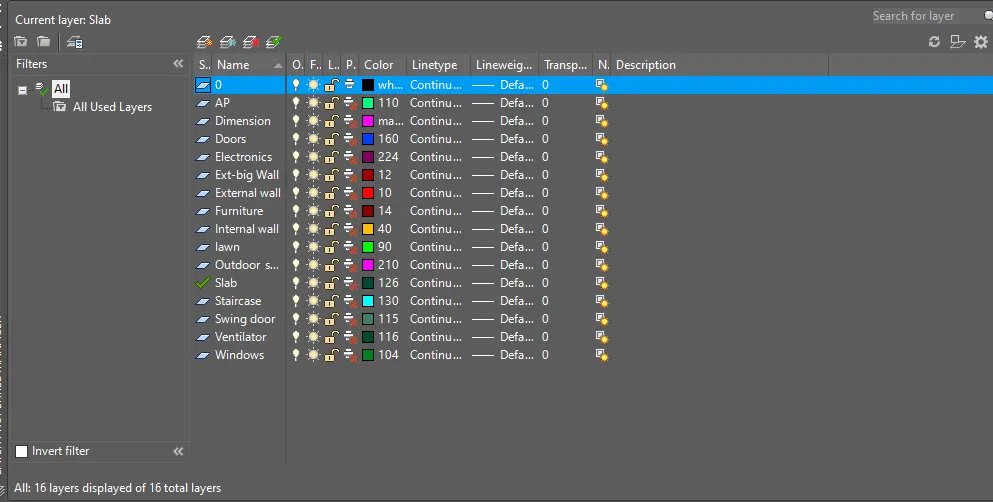
Annotate Tab
- In Annotate Tab ---->Modify dimension style---->Text and Style
- Changing the style from ISO25 to Comic San----> Set current----->Apply
TEXT
- TEXT is used to write the name of the furniture and electronic items at the specified location
- TEXT is used to write the dimensions and names of the different rooms
ERASE
- ERASE is used to erase the unwanted lines which cannot be trimmed using Trim Command
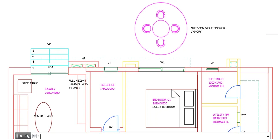
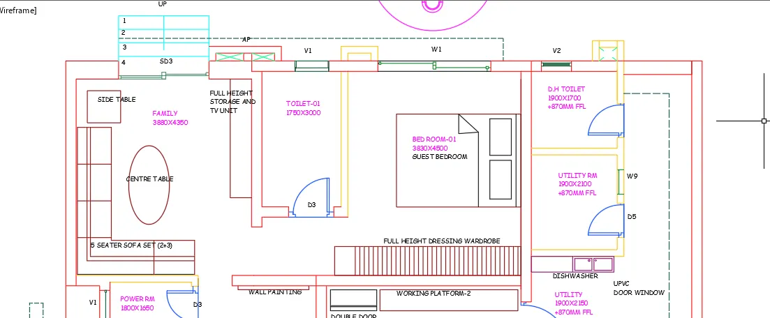
Result:
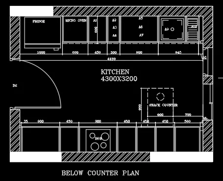
KITCHEN PLAN
Aim: To draft the floor plan of the house and dimensioning it using AutoCAD
Procedure:
- Open AutoCad
- Selecting metric system
- Command UN(units) and selecting decimals with precision of 0
- Command LIMITS and having limit of (0,0) in lower left corner and (10000,10000) in upper right corner
- Command ZOOM and selecting All
Commands used:
XLINE
- XLINE horizontal and vertical is used to start the drawing initally
LINE
- LINE is used to draw the line in the Window and Doors at required spaces
OFFSET
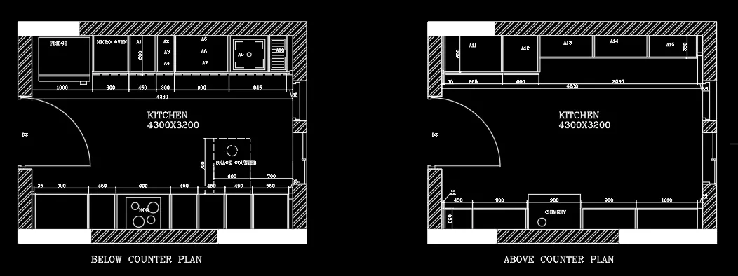
Sketching below counter plan
- OFFSET is used to offset the external walls to 230mm
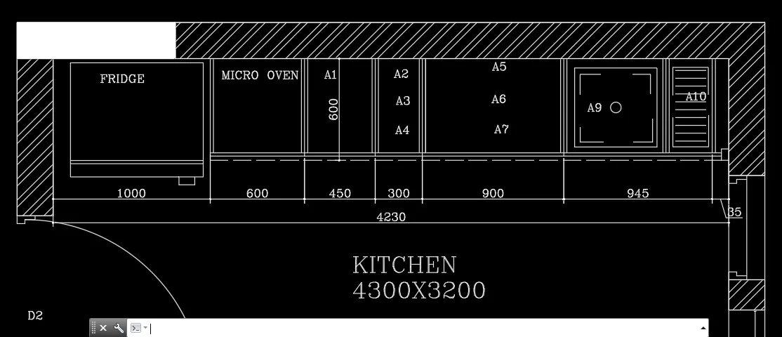
- OFFSET is used to offset the Working platform 1 for 1000, 600, 450, 300, 900, 945 and 35 respectively in horizontal direction
- OFFSET is used to offset the Working platform 1 for 600mm vertically
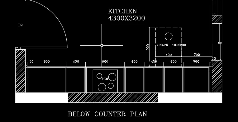
- OFFSET is used to offset the Working platform 2 for 35, 900, 450, 900, 450, 450, 450, 560 and 35 respectively in horizontal direction
- OFFSET is used to offset the Working platform 2 for 600mm vertically
- OFFSET is used to offset the 700 mm from right wall horizontally and 900 mm vertically for snack counter
- OFFSET is used to offset 12mm on both sides to the main offsetted line to dimension it center to center
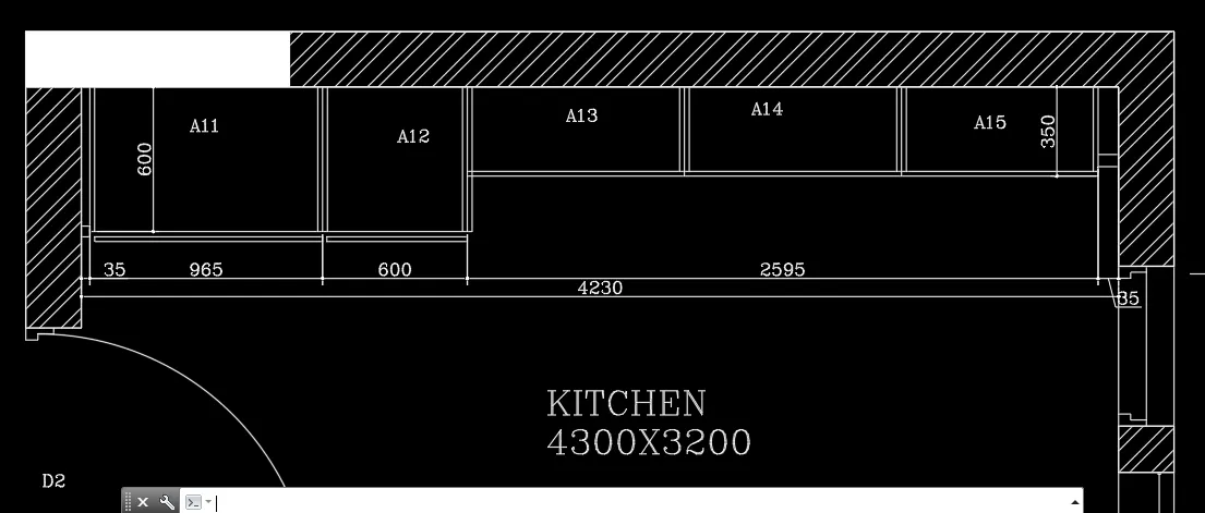
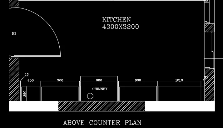
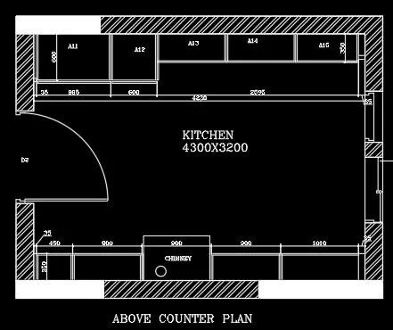
Sketching above counter plan
- OFFSET is used to offset the external walls to 230mm
- OFFSET is used to offset the Working platform 1 for 35, 965, 600, 2595 and 35 respectively in horizontal direction
- OFFSET is used to offset the Working platform 1 for 600 and 350 mm in vertical direction
- OFFSET is used to offset the Working platform 2 for 35, 450, 900, 900, 900, 1010 and 35 respectively in horizontal direction
- OFFSET is used to offset the Working platform 2 for 350mm in vertical direction
- OFFSET is used to offset 12mm on both sides to the main offsetted line to dimension it center to center
PLINE
- PLINE is used to draw the fridge, Micro oven, Hob, sink and Chimney both in below and above counter plan
DDptype
- Changing the points to visible points to divide the line
DIVIDE
- Dividing the 2595 line into 3 equal parts
DIMBREAK
- DIMBREAK is used to break the dimensions which are crossing each other in snack counter 900mm dimension line is breaked from 450mm line
TRIM
- TRIM is used to trim the unwanted lines
CIRCLE
- CIRCLE is used to draw the Sink hole, Snack counter ,hob and Chimney
ARC
- ARC is used to draw the doors with Start,Center and End
LINETYPE
- LINETYPE is to change the Continuous line to Dash line and changing the scale to 20
Annotate Tab
- In Annotate Tab ---->Modify dimension style---->Text and Style
- Changing the style from ISO25 to Romanc.shx----> Set current----->Apply
DIMLINEAR
- DIMLINEAR is used to dimension the working platform 1 and 2
DIMCONTINUE
- DIMCONTINUE is used to dimension quickly using after DIMLNEAR command for working platforms
TEXT
- TEXT is used to write the name of the electronic items at the specified location like Fridge, Micro oven etc
- TEXT is used to write the dimensions of different compartment like A1 to A15
ERASE
- ERASE is used to erase the unwanted lines which cannot be trimmed using Trim Command
Result
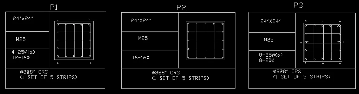
COLUMN SCHEDULE
Aim: To Schedule the column using AutoCAD
Procedure:
- Open AutoCad
- Selecting imperial system
- Command UN(units) and selecting Engineering with precision of 0'-0"
- Command LIMITS and having limit of (0,0) in lower left corner and (100',100') in upper right corner
- Command ZOOM and selecting All
Commands Used
- LINE
- OFFSET
- TRIM
- DDPTYPE
- DIVIDE
- CIRCLE
- FILLET
- LWEIGHT
- SCALE
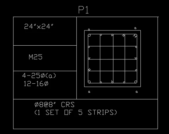
Drawing the P1
- Type Command LINE and draw 24" horizontal line and 24" vertical line on both the sides
- Type Command OFFSET and draw an offset of 1" on all 4 sides
- Type Command TRIM and trim the unwanted lines
- Type Command DDPTYPE and select suitable point type
- Type Command DIVIDE and divide the line into 4 segments on 24" of both sides
- Type Command CIRCLE of diameter of 25mm=1" of 4 numbers at 4 corners
- Type Command CIRCLE of diameter of 16mm=0.62" of 12 numbers at remaining place
- Type Command FILLET of radius of 1" at 4 corners
- Type Command TEXT of height 8" and style of Roman.shx and angle of 0 degree and type 24"X24", M25, 4-25dia( type %%C for diameter symbol), 12-16dia(type %%C for diameter symbol), (type %%C for diameter symbol)8@8" CRS ( 1 SET OF 5 STRIPS)
- Command LWEIGHT and draw a stirups of 8mm dia at the required places
- Command SCALE and scale the texts and diagram
- Command LINE and draw a line like table and place the texts and diagram in suitable places.
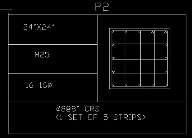
Drawing the P2
- Type Command LINE and draw 24" horizontal line and 24" vertical line on both the sides
- Type Command OFFSET and draw an offset of 1" on all 4 sides
- Type Command TRIM and trim the unwanted lines
- Type Command DDPTYPE and select suitable point type
- Type Command DIVIDE and divide the line into 4 segments on 24" of both sides
- Type Command CIRCLE of diameter of 16mm=0.62" of 16 numbers
- Type Command FILLET of radius of 0.62" at 4 corners
- Type Command TEXT of height 8" and style of Roman.shx and angle of 0 degree and type 24"X24", M25, 16-16dia( type %%C for diameter symbol)and (type %%C for diameter symbol)8@8" CRS ( 1 SET OF 5 STRIPS)
- Command LWEIGHT and draw a stirups of 8mm dia at the required places
- Command SCALE and scale the texts and diagram
- Command LINE and draw a line like table and place the texts and diagram in suitable places.
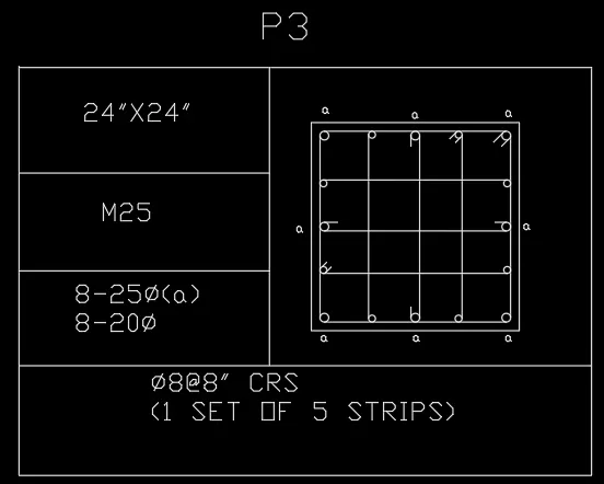
Drawing the P3
- Type Command LINE and draw 24" horizontal line and 24" vertical line on both the sides
- Type Command OFFSET and draw an offset of 1" on all 4 sides
- Type Command TRIM and trim the unwanted lines
- Type Command DDPTYPE and select suitable point type
- Type Command DIVIDE and divide the line into 4 segments on 24" of both sides
- Type Command CIRCLE of diameter of 25mm=1" of 8 numbers at 4 corners and at middle
- Type Command CIRCLE of diameter of 20mm=0.79" of 8 numbers at remaining place
- Type Command FILLET of radius of 1" at 4 corners
- Type Command TEXT of height 8" and style of Roman.shx and angle of 0 degree and type 24"X24", M25, 8-25dia( type %%C for diameter symbol), 8-20dia(type %%C for diameter symbol), (type %%C for diameter symbol)8@8" CRS ( 1 SET OF 5 STRIPS)
- Command LWEIGHT and draw a stirups of 8mm dia at the required places
- Command SCALE and scale the texts and diagram
- Command LINE and draw a line like table and place the texts and diagram in suitable places.
Result
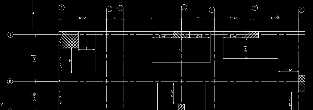
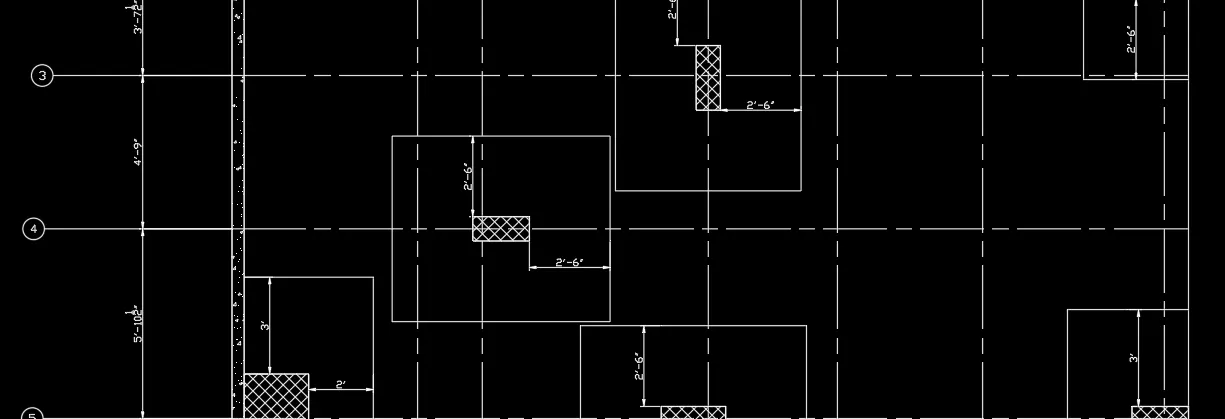
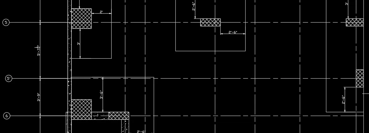
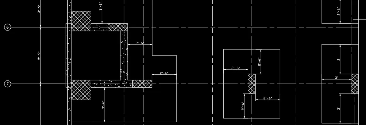
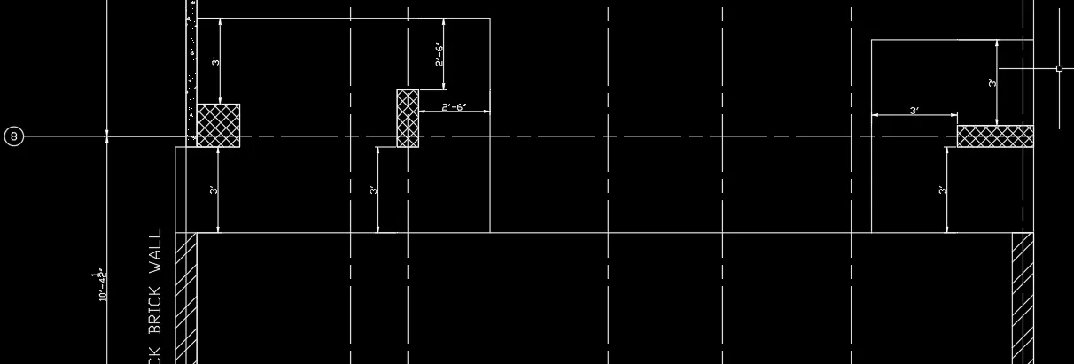
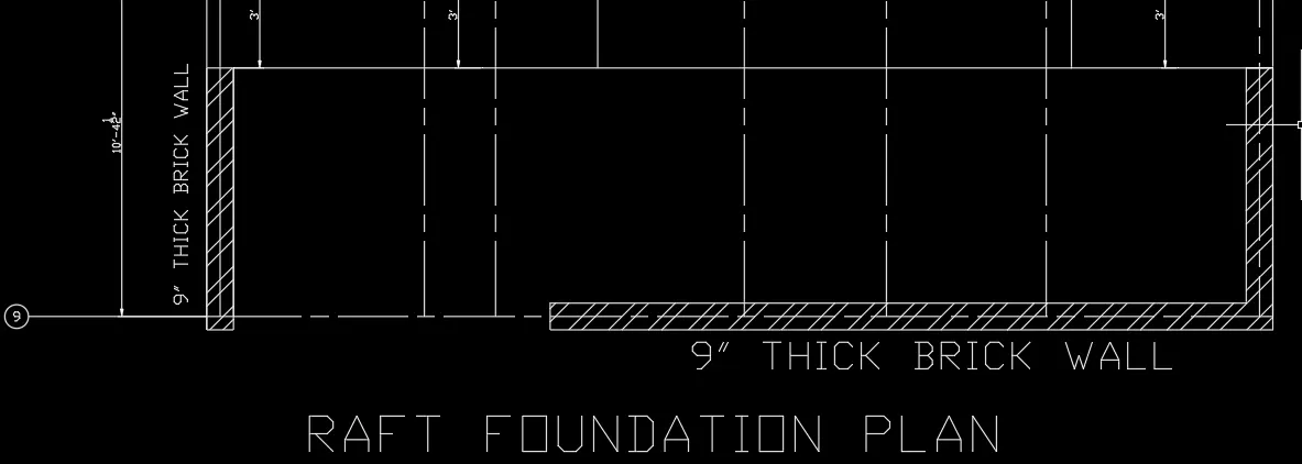
RAFT FOUNDATION PLAN
Aim: To draft the Raft foundation and dimensioning it using AutoCAD
Procedure:
- Open AutoCad
- Selecting Imperial system
- Command UN(units) and selecting Architectural with precision of 0'-1/256"
- Command LIMITS and having limit of (0,0) in lower left corner and (1000',1000') in upper right corner
- Command ZOOM and selecting All
Commands used:
XLINE
- XLINE horizontal and vertical is used to start the drawing initally
OFFSET
- OFFSET is used to offset the XLINE horizontal 5'-7.5"
- OFFSET is used to offset the 5'-7.5" to 3'-7.5"
- OFFSET is used to offset the 3'-7.5" to 4'-9"
- OFFSET is used to offset the 4'-9" to 5'-10.5"
- OFFSET is used to offset the 5'-10.5" to 5'-7.5"
- OFFSET is used to offset the 5'-7.5" to 3'-9"
- OFFSET is used to offset the 3'-9" to 5'-9"
- OFFSET is used to offset the 5'-9" to 13'-10.5"
- OFFSET is used to offset the 13'-10.5" to 10'-4.5"
- OFFSET is used to offset the XLINE vertical 5'-9"
- OFFSET is used to offset the 5'-9" to 2'
- OFFSET is used to offset the 2' to 7'
- OFFSET is used to offset the 7' to 4'
- OFFSET is used to offset the 4' to 4'-6"
- OFFSET is used to offset the 4'-6" to 5'-7.5"
- OFFSET is used to offset the 5'-7.5" to 9" thick wall
- OFFSET is used to offset the foundations to 3',2'-6" and 2' respectively
TRIM
- TRIM is used to trim the unwanted lines
FILLET
- FILLET is fillet the offsetted foundation concrete distance with radius 0
PLINE
- PLINE is used to draw the foundation of 24"x24", 9"x24",9"x21" and 9"x30" respectively
MLEADERSTYLE
- MLEADERSTYLE-----> content----> mleader type-----> Block----> source block---->circle
MLEADER
- MLEADER is used to leader the horizontal lines as 1 to 8
- MLEADER is used to leader the vertical lines as A,B,C,D,E,F and G
LINETYPE
- LINETYPE is to change the Continuous line to ISO long dash short dash line and changing the scale to 10
DIMLINEAR
- DIMLINEAR is used to dimension the offsetted line
DIMCONTINUE
- DIMCONTINUE is used to dimension quickly using after DIMLiNEAR command for offsetted line
HATCH
- HATCH is used to hatch the foundation to ANS137 for 24"x24", 9"x24",9"x21" and 9"x30"
- HATCH is used to hatch the concrete portion to AR-CONC
- HATCH is used to hatch the 9" thick brick wall to ANS132
TEXT
- TEXT is used to write the 9" thick brick wall With height 2" and 0 angle
- TEXT is used to write the Raft Foundation PLan with height 3" and 0 angle
ERASE
- ERASE is used to erase the unwanted lines which cannot be trimmed using Trim Command
Result: