Aston Martin ONE-77 Challenge-11 (Project)
SURFACE MODELLING OF ASTON MARTIN CAR USING SOLID WORKS
OBJECTIVE:
To design ASTON MARTIN by using given blue prints with surface & solid modelling techniques.
INTRODUCTION:
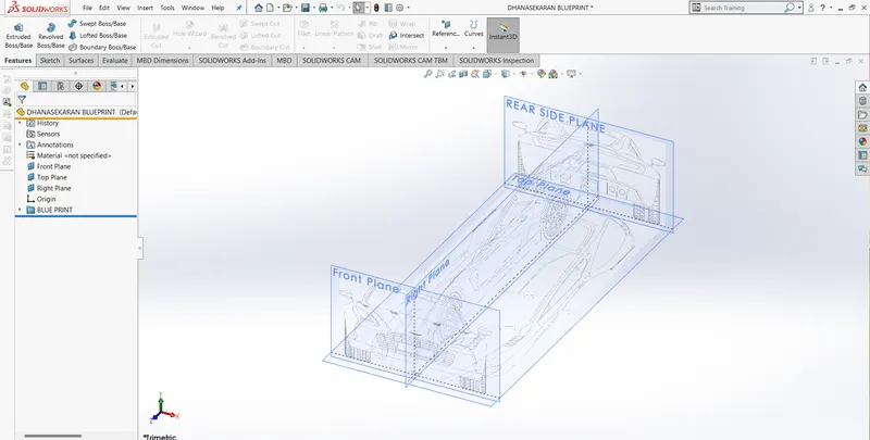
In this course we learn advanced surface modelling techniques in SOLIDWORKS. We use bule prints to create outer sketch of the aston martin car and then we use various surface and solid modelling techniques. Then the surface and solidmodeling parts well assembled in assembly workbech and rendered as final output.
DESIGN APPROACH METHODOLOGY:
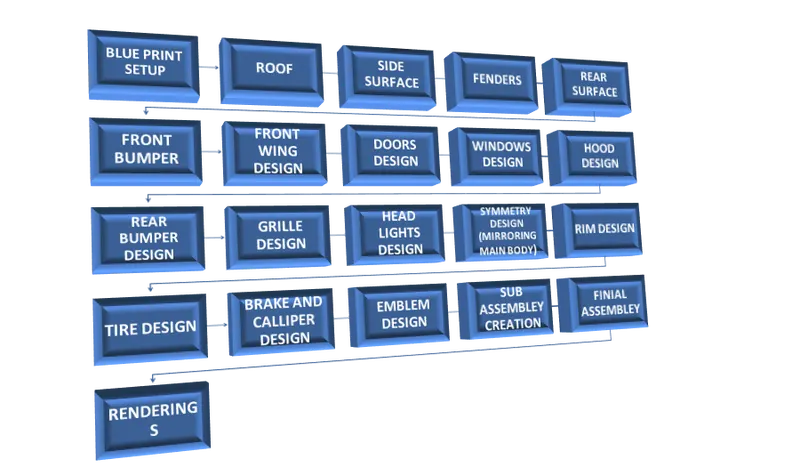
DESCRIPTION OF FEATURES USED:
SURFACE FEATURES:
BOUNDARY SURFACE:
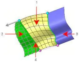
The boundary surface feature lets you create surfaces that can be tangent or curvature continuous in both directions (all sides of the surface). In most cases, this delivers a higher quality result than the loft tool.
SURFACE EXTRUDE:
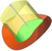
create extruded surfaces from models that include 2D or 3D faces and knit the extruded surfaces to surrounding features.
RULED SURFACE:
The Ruled Surface command creates surfaces that extend out in a specified direction from selected edges.
SURFACE EXTEND:
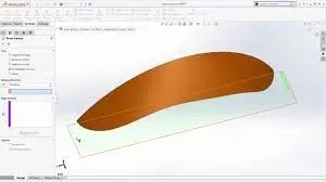
Extend a surface by selecting an edge, multiple edges, or a face.
LOFT SURFACE:
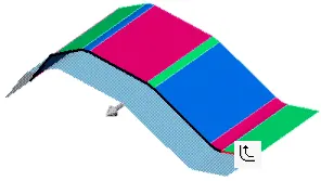
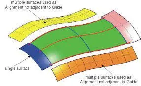
Loft Surfaces are surfaces generated by multiple 3D Curves or existing edges creating a smooth tangency between the selected curves. Match Points are created between each selection denoting the orientation and path of the loft surface.
SURFACE TRIM:
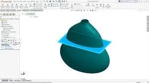
surface, plane, or sketch as a trim tool to trim intersecting surfaces. You can also use a surface in conjunction with additional surfaces, as mutual trim tools.
SURFACE FILL:
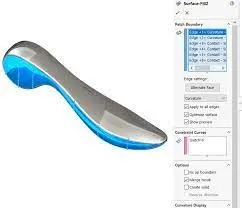
The Filled Surface feature constructs a surface patch with any number of sides, within a boundary defined by existing model edges, sketches, or curves, including composite curves.
SURFACE KNIT:
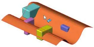
Knit Surface tool to combine two or more faces and surfaces into one.
SURFACE CUT:
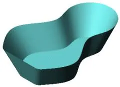
Surface cut a solid model by removing material with a surface or plane. With multibody parts, you can select which bodies to keep.
SOLID FEATURES:
EXTRUDE:
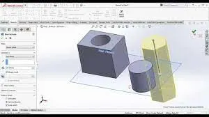
Extrude tool is used to extend a sketched profile in one or two directions as either a thin feature or a solid feature. An extrude operation can either add material to a part (in a base or boss) or remove material from a part.
CUT EXTRUDE:
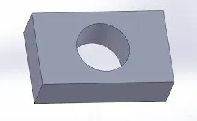
Extruded cut feature removes material from the part.
REVOLVE BOSS BASE:
To create a revolve feature: Create a sketch that contains one or more profiles and a centerline, line, or edge to use as the axis around which the feature revolves. Click one of the following revolve tools.
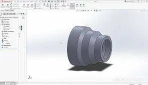
FILLET:
Fillets describe rounded corners of a design (or part) that help to reduce stresses and prevent rapid deformation at the corners of the part.
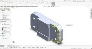
CHAMFER:
A chamfer is the sloped or angled edges or corners of a part design. It is an antonym of the fillet. Instead of having a curved shape, a chamfer is straight and has a sharp angle.
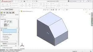
FLEX:
The flex feature calculates the extents of the part using a bounding box. The trim planes are then initially located at the extents of the bodies, perpendicular to the Z-axis of the triad.
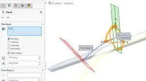
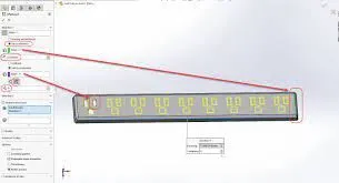
LINEAR PATTERN:
Linear patterns to create multiple instances of one or more features that you can space uniformly along one or two linear paths.
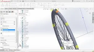
CIRCULAR PATTERN:
Circular patterns to create multiple instances of one or more features that you can space uniformly around an axis.
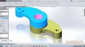
MOVE/COPY SOLID BODIES:
It is used to move, rotate, and copy solid and surface bodies, or place them using mates.
ADDITIONAL FEATURES:
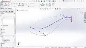
PROJECTED CURVE:
Create a Curve as the intersection of two projected sketches. Note that the projections from one sketch must intersect the other in one contiguous curve for this operation to succeed.
SPLIT LINE:
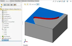
The Split Line. tool projects an entity (sketch, solid, surface, face, plane, or surface spline) to surfaces, or curved or planar faces. It divides a selected face into multiple separate faces.
INTERSECTION CURVE:
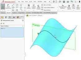
Intersection Curve. opens a sketch and creates a sketched curve at the following kinds of intersections: A plane and a surface or a model face.
CONVERT ENTITIES:
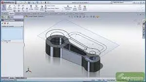
Whenever we need to make a sketch entity that matches other geometry of our model we can use the Convert Entities tool.
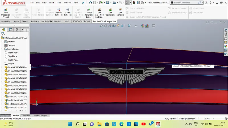
COMPONENTS DESIGNED:
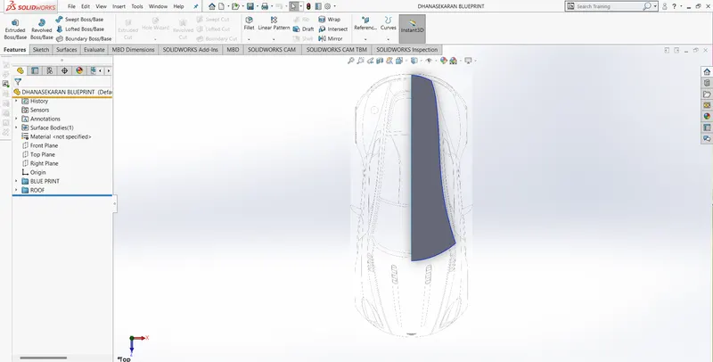
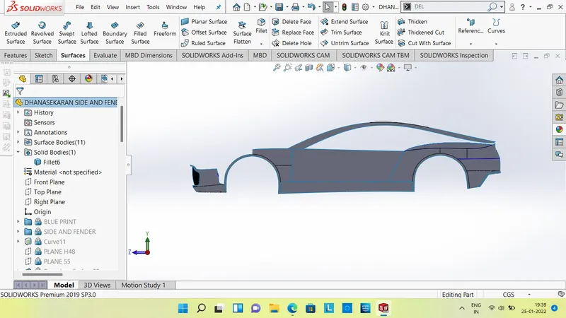
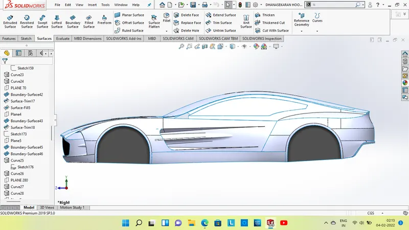
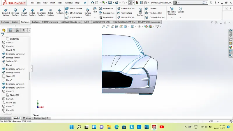
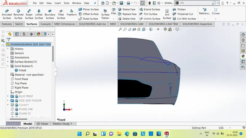
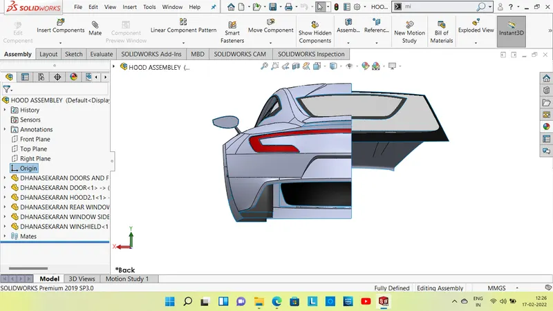
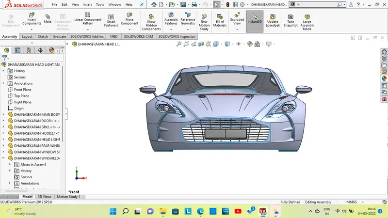
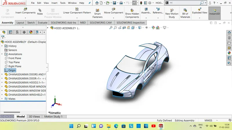
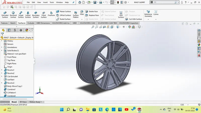
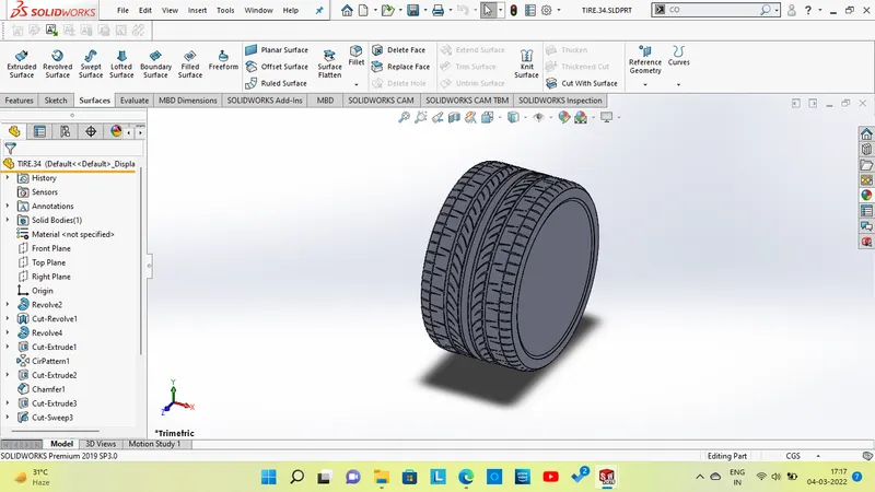
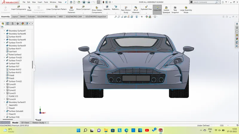
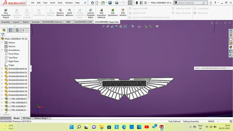
RENDERING IMAGES:



CONCLUSION:
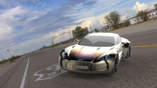
The ASTON MARTIN CAR designed successfully by using surface and solid modelling in solid works and assembled in assembly workbech successfully and rendered in solidworks visualize.