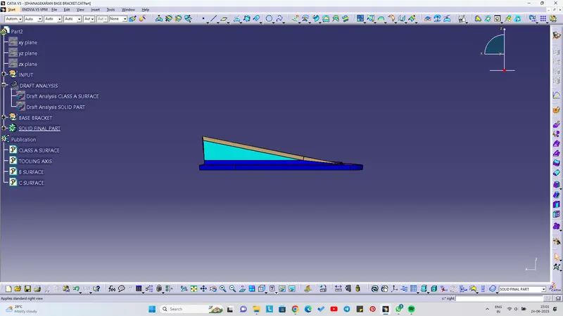
Week 9 - Challenge 1 - Base Bracket Design
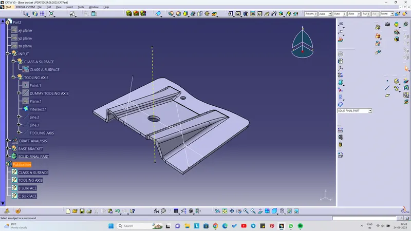
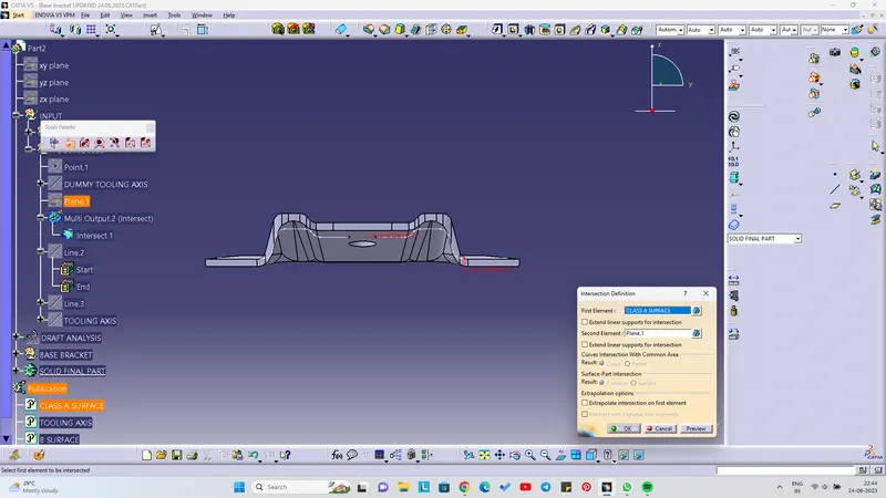
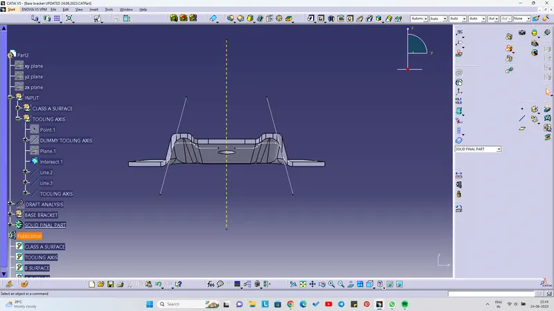
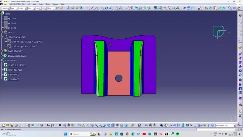
METHOD FOR DRAFT ANALYSIS - First I checked the possible direction for the draft analysis in my case the z-direction was the best possible way to take the draft analysis, then I created the dummy tooling axis for the reference of x,y,z-direction.then took a plane in refrence to yz-plane and took a intersection in that plane, then created the construction lines for those surface which are going to cause problem.then created the bisecting line by selecting the two construction lines. then hide all other things on the workbench other than the bisecting line that was created as main tooling axis. then changed the color for that line. After that switched to material view and started the draft analysis tool and then bring the cursor to the tooling axis, then clicked on the surface to see the minimum draft analysis in my case it was 3 degree. So, i have designed the complete the CLASS B AND CLASS C Surface according to that.
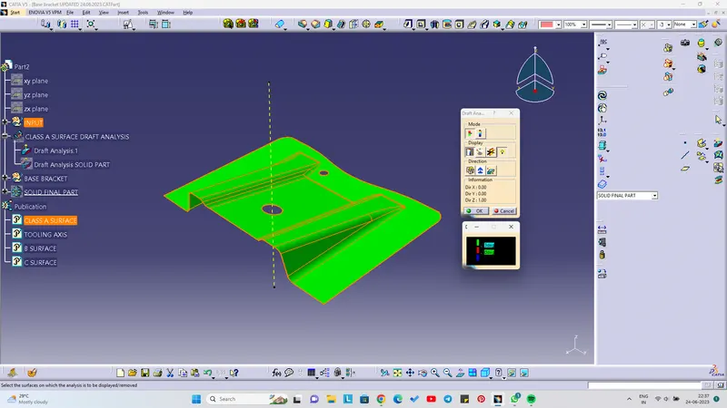
Image of the complete Draft analysis of class A
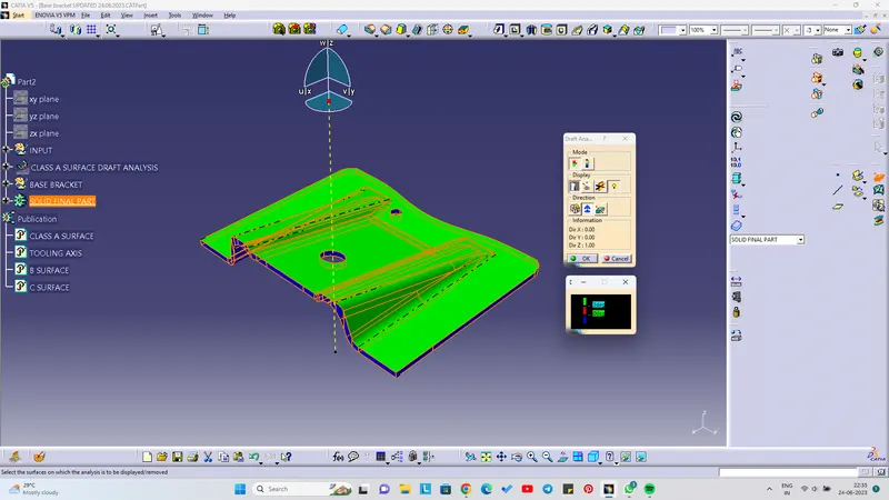
Image of the complete Draft analysis of Final Solid Model
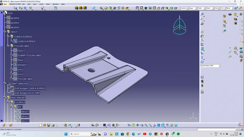
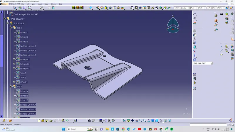
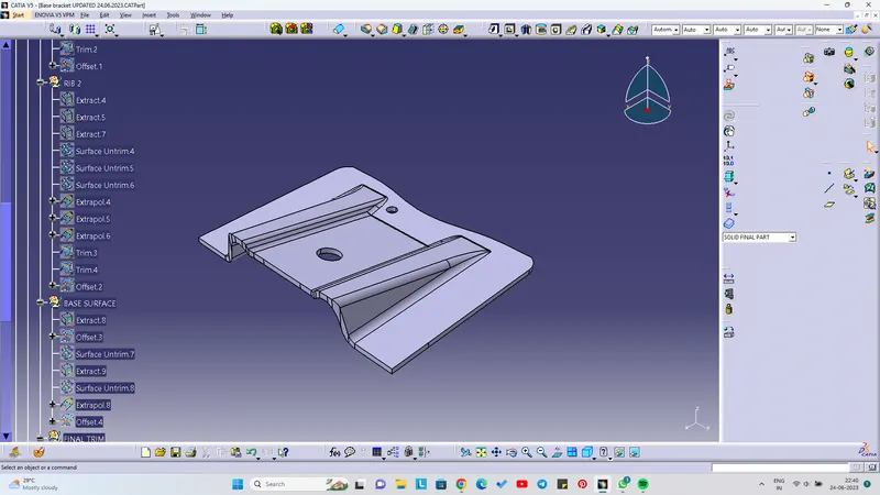
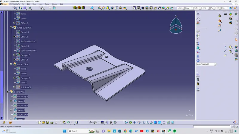
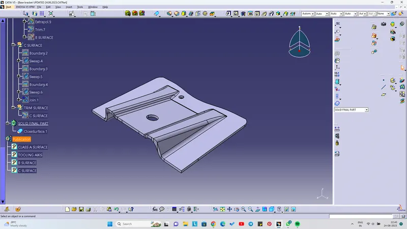
Tooling Axis Creation
- Take the class A surface
- Select the centre hole and create the Origin Point
- Choose the Line command and make the axis which will pass through the centre of the Hole.
- Choose the Intersection option
- Click the pane on which intersection line to be projected then touch the class A surface.
- click line command (point to point) and touch both sides of 2 points which makes the draft angle then extend in bi-direction.
- Choose the Line command then go for Bisection Method
- Click both side lines and then touch the Origin.
- A centre line will create which will describe the Tooling direction of the tool with respect to Draft.
TOP VIEW
ISOMETRIC VIEW
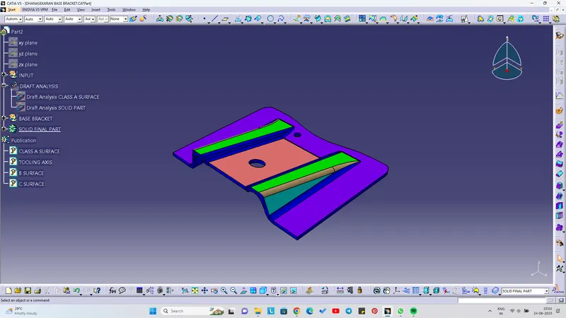
FRONT VIEW
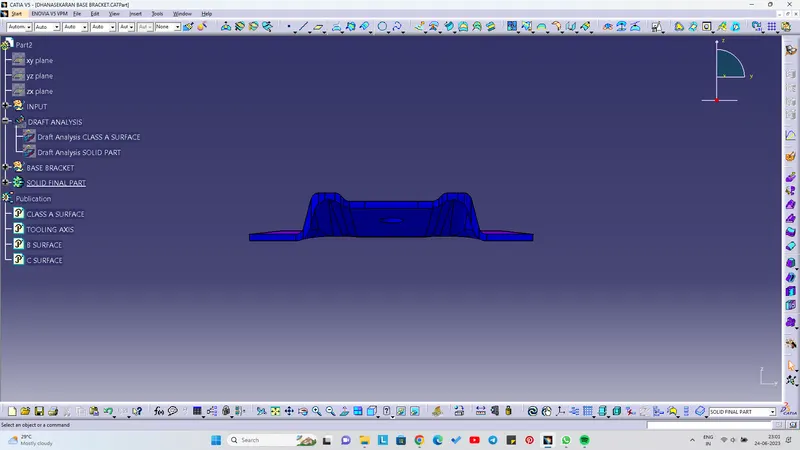
RIGHT SIDE VIEW